Table of Contents
Advertisement
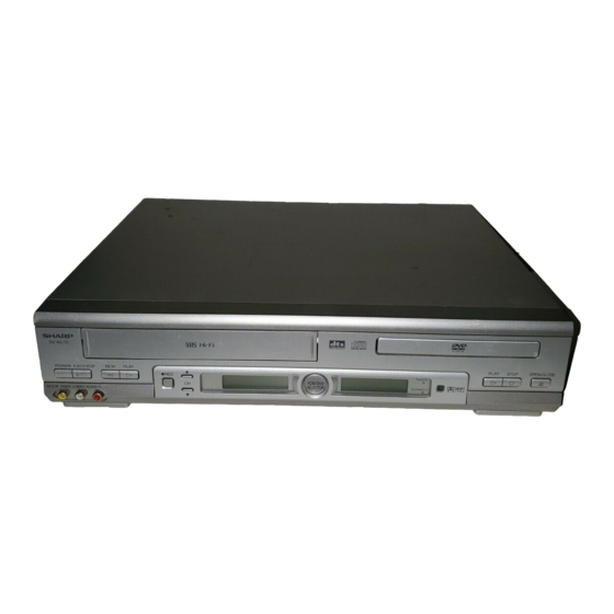
POWER EJECT/STOP
REW
PLAY
/
REC
VCR/DVD
CH
SELECTOR
AV 2 IN VIDEO L(MONO)-AUDIO-R
1. IMPORTANT SERVICE NOTES ........................................................................................................ 2
2. FEATURES ........................................................................................................................................ 4
3. SPECIFICATIONS ............................................................................................................................. 4
4. PART NAMES .................................................................................................................................... 6
5. MAINTENANCE CHECK ITEMS AND EXECUTION TIME ............................................................... 9
6. DISASSEMBLY METHOD ............................................................................................................... 10
7. OPERATION OF PICKUP ............................................................................................................... 14
8. ADJUSTMENT, REPLACEMENT AND ASSEMBLY OF MECHANICAL UNITS ............................ 15
9. TEST MODE .................................................................................................................................... 38
10. TROUBLESHOOTING ..................................................................................................................... 41
11. BLOCK DIAGRAMS ......................................................................................................................... 52
12. SCHEMATIC DIAGRAMS ................................................................................................................ 60
13. PRINTED WIRING BOARD ASSEMBLIES ..................................................................................... 74
14. REPLACEMENT PARTS LIST ........................................................................................................ 89
15. PACKING OF THE SET ................................................................................................................. 106
SHARP CORPORATION
SERVICE MANUAL
VCR/DVD COMBINATION MODEL
PLAY
STOP
OPEN/CLOSE
TIMER
VCR DVD
MODELS
In the interests of user-safety (Required by safety regula-
tions in some countries) the set should be restored to its
original condition and only parts identical to those specified
be used.
CONTENTS
1
DV-NC70U
DV-NC70C
DV-NC72U
This document has been published to be used for
after sales service only.
The contents are subject to change without notice.
DV-NC70U/C
DV-NC72U
S62K3DV-NC70U
Page
Advertisement
Table of Contents

Related Manuals for Sharp DV-NC70U


Summary of Contents for Sharp DV-NC70U
-
Page 1: Table Of Contents
DV-NC70U/C DV-NC72U SERVICE MANUAL S62K3DV-NC70U VCR/DVD COMBINATION MODEL DV-NC70U POWER EJECT/STOP PLAY PLAY STOP OPEN/CLOSE DV-NC70C TIMER VCR/DVD SELECTOR VCR DVD AV 2 IN VIDEO L(MONO)-AUDIO-R DV-NC72U MODELS In the interests of user-safety (Required by safety regula- tions in some countries) the set should be restored to its original condition and only parts identical to those specified be used. -
Page 2: Important Service Notes
DV-NC70U/C DV-NC72U 1. IMPORTANT SERVICE NOTES BEFORE RETURNING THE VCR/DVD COMBINA- etc.) and measure the AC voltage drop across the resistor. Reverse the AC plug on the set and repeat TION MODEL AC voltage measurements for each exposed part. Before returning the video cassette recorder to the user, Any reading of 0.45V rms (this corresponds to 0.3mA... - Page 3 DV-NC70U/C DV-NC72U 1. NOTES DE SERVICE IMPORTANTES AVANT DE RENDRE LE VCR/DVD MAGNETOSCOPE pièces métalliques exposées ayant un parcours de retour au châssis (connexions d’antenne, coffret métallique, tétes de vis, boutons et arbres de Avant de rendre le magnétoscope à l’utilisateur, effectuer commande, etc.) et mesurer la chute de tension CA...
-
Page 4: Features
• S-VHS Quasi Playback • 19 Clear Picture System (in EP mode) • Simple Recording Timer • Sharp Super Picture • Exact Rec/Tape Remaining Ë Ë Ë Ë Ë DVD • Plays DVD, CD (Digital Audio) discs as well as CD-R/CD-RW discs recorded in MP3 file format •... - Page 5 DV-NC70U/C DV-NC72U Channel Coverage VHF 2-13 UHF 14-69 CATV 1-125 Antenna Input Video Input Input level: 0.5 to 2.0 Vp-p (75 ) Video Output Output level: 1.0 Vp-p (75 ) Audio Output Input level: –8 dBs (47k ) (0 dB = 0.775 Vrms) Audio Output Output level: –8 dBs (1k )
-
Page 6: Part Names
DV-NC70U/C DV-NC72U 4. PART NAMES... - Page 7 DV-NC70U/C DV-NC72U...
- Page 8 DV-NC70U/C DV-NC72U...
-
Page 9: Maintenance Check Items And Execution Time
DV-NC70U/C DV-NC72U 5. MAINTENANCE CHECK ITEMS AND EXECUTION TIME MECHANICAL PARTS REGUIRING PERIODICAL INSPECTION Use the following table as a guide to maintain the mechanical parts in good operating condition. Maintained 1,000 hrs. 2,000 hrs. Parts Pickup Spindle Unit Sled Motor... -
Page 10: Disassembly Method
DV-NC70U/C DV-NC72U 6. DISASSEMBLY METHOD 6-1. DISASSEMBLY METHOD 1) Removing the cabinet. (1) Remove the four screws 1 and one screw 2. 2) Removing the front panel. (1) Remove the two screws 3. (2) Release the six hooks 4. 3) Removing the front PWB. - Page 11 DV-NC70U/C DV-NC72U (6) Remove the two screws e to remove the Power PWB Unit. 5) Removing the Cassette Housing Control/VCR Mechanism. (1) Remove the two screws r. (2) Remove the one screw t. (3) Remove the two screws y. 6) Removing the Antenna Terminal Cover/VCR Main PWB Unit.
- Page 12 DV-NC70U/C DV-NC72U 6-2. EXTENSION CABLE USE POINT (ONE PLACE) Parts Code Price Code Name/Description QCNW-8571GEZZ Extension cable (wire), 9pin 500mm DVD Main CN3201–Power CN201 Extension Cable Diagram Tuner QCNW-8571GEZZ 9 pin Power PWB DVD Mechanism CN201 VCR Main PWB VCR Mechanism...
- Page 13 DV-NC70U/C DV-NC72U 6-3. REPLACEMENT OF MAIN PARTS <Take out disk> 1. Remove the mechanism with angle from the set. (refer to 33 on page 104. Remove K , M , N ) 2. It is in such cases as the thin driver, and it is pushed in slowly, and a tray is drawn in the arrow direction the Slide Rack on the left of the base chassis.
-
Page 14: Operation Of Pickup
DV-NC70U/C DV-NC72U 7. OPERATION OF PICKUP 7-1. CIRCUIT CONFIGURATION OF PICKUP The pickup unit reads signals from the disk, and the flexible cable is connected to the board. The following signals flow through the cable. 7-3. POLARITIES OF SIGNAL 7-2. EQUIVALENT CIRCUIT OF PICKUP... -
Page 15: Adjustment, Replacement And Assembly Of Mechanical Units
DV-NC70U/C DV-NC72U 8. ADJUSTMENT, REPLACEMENT AND ASSEMBLY OF MECHANICAL UNITS The explanation given below relates to the on-site general service (field service) but it does not relates to the adjustment and replacement which need high-grade equipment, jigs and skill. For example, the drum assembling, replacement and adjustment service must be performed by the person who have finished the technical courses. - Page 16 DV-NC70U/C DV-NC72U 8-2 MAINTENANCE CHECK ITEMS AND EXECUTION TIME Perform the maintenance with the regular intervals as follows so as to maintain the quality of machine. Maintained 1000 1500 2000 Possible symptom Remarks hrs. hrs. hrs. hrs. encountered Parts Abnormal rotation or significant Guide roller ass’y...
- Page 17 DV-NC70U/C DV-NC72U 8-3. FUNCTION OF MAJOR MECHANICAL PARTS (TOP VIEW) Function Function Full erase head Reverse guide lever ass’y Supply pole base ass’y Reel relay gear Tension arm Take-up reel disk Idler wheel ass’y Pinch roller lever ass’y Open guide...
- Page 18 DV-NC70U/C DV-NC72U FUNCTION OF MAJOR MECHANICAL PARTS (BOTTOM VIEW) Function Function Syncro Gear Clutch lever Master cam Limiter pulley ass’y Capstan D.D. motor Shifter Reel belt...
-
Page 19: Disassembly And Reassembly
DV-NC70U/C DV-NC72U 8-4. DISASSEMBLY AND REASSEMBLY 8-4-1 DISASSEMBLING THE MECHANISM 2. Removing the mechanism and cassette housing. 1. When removing the mechanism from the set. Remove the two screws 2 fixing the cassette housing Remove the two screws 1 which connecting mechanism to the mechanism, and remove the cassette housing. - Page 20 DV-NC70U/C DV-NC72U 2. Mechanical initial setting • Rotate the worm gear by pushing the flange manually • The maximum applied voltage is 9V. If more than 9V, until return to initial position. there is a possibility the mechanism will damage.
- Page 21 DV-NC70U/C DV-NC72U 8-5 REMOVING AND INSTALLING THE CAS- Notes SETTE HOUSING 1. In the case when you use the magnet screw driver, never approach the magnet driver to the A/C head, FE head, • Removal and drum. 1. In the cassette removing mode, remove the cassette.
- Page 22 DV-NC70U/C DV-NC72U 8-7 REEL DISK REPLACEMENT AND HEIGHT Notes: CHECK 1. When installing the reel disk, take due care so that the tension band ass'y is not deformed and grease does no • Removal adhere. 1. Remove the cassette housing control assembly.
- Page 23 DV-NC70U/C DV-NC72U Note: Notes: Whenever replacing the reel disk, perform the height check- 1. Hold the torque gauge by hand so that it is not moved. ing and adjustment. 2. Do not keep the reel disk in lock state. Do not allow long- time measurement.
- Page 24 DV-NC70U/C DV-NC72U Notes: 8-11 CHECKING AND ADJUSTMENT OF TAKE- 1. Hold the torque gauge by hand so that it is not moved. UP TORQUE IN VIDEO SEARCH REWIND 2. Do not keep the reel disk in lock state. Do not allow long- MODE time measurement.
- Page 25 DV-NC70U/C DV-NC72U 8-12 CHECKING THE VIDEO SEARCH REWIND BACK TENSION • Remove the cassette housing control assembly. • After short-circuiting between TP803 and TP802 provided at main PWB, plug in the power cord. Tension gauge Pinch roller 900 - 1,200gf •...
- Page 26 DV-NC70U/C DV-NC72U • Checking Tension pole adjustment driver adjusting direction 1. Set a cassette tape, push the REC button to place the unit in the SP record mode. Now check the tension pole position. 2. Visually check to see if the position of the tension pole is +0.5...
- Page 27 DV-NC70U/C DV-NC72U • Adjustment • Checking the brake torque at the take-up side 1. If the indication of torque cassette meter is lower than the setting, shift the tension spring engagement to the part A. Torque gauge 2. If the indication of torque cassette meter is higher than the setting, shift the tension spring engagement to the part B.
- Page 28 DV-NC70U/C DV-NC72U 8-17 REPLACEMENT OF A/C (AUDIO/CONTROL) 3. Align the left end of gear of A/C head arm with the punched mark of chassis, tentatively tighten the screws HEAD 1 so as to ensure smooth motion of A/C head arm.
- Page 29 DV-NC70U/C DV-NC72U 8-18 A/C HEAD HEIGHT ROUGH ADJUSTMENT 8-19 ADJUSTMENT OF TAPE DRIVE TRAIN • Setting 1. Tape run rough adjustment 1 Check and adjust the position of the tension pole. (See 8-14.) 2 Check and adjust the video search rewind back Azimuth screw tension.
- Page 30 DV-NC70U/C DV-NC72U Notes: 3 Next, press the tracking button (+), (–) and change 1. Previously set the tracking control in the center position, the ATR signal waveform from max to min and from and adjust the ATR signal waveform to maximum with X min to max.
- Page 31 DV-NC70U/C DV-NC72U When the tape is above the helical lead. When the tape is below the helical lead. Supply side Take-up side Supply side Take-up side Supply side guide roller Take-up side guide roller Supply side guide roller Take-up side guide roller...
- Page 32 DV-NC70U/C DV-NC72U 8-21 REPLACEMENT OF DRUM D.D. MOTOR 8-20 REPLACEMENT OF THE CAPSTAN D.D. 1. Set the ejection mode. (DIRECT DRIVE) MOTOR 2. Withdraw the main power plug from the socket. • Remove the mechanism from the set. • Removal (Perform in numerical order.) •...
- Page 33 DV-NC70U/C DV-NC72U 8-22 REPLACING THE UPPER AND LOWER 8-23 ASSEMBLING OF PHASE MATCHING DRUM ASSEMBLY MECHANISM COMPONENTS • Replacement (Perform in the numerical order) • Assemble the phase matching mechanism compo- 1 Remove the motor as stated in 8-21 Replacement of nents in the following order.
- Page 34 DV-NC70U/C DV-NC72U 1. Make sure that the loading arm T and S are at the Phase- 8-24 INSTALLING THE SHIFTER Matching point as shown below 2. Fix the shifter position setting part to the roading arm T Drum position setting part as shown in figure 3.
- Page 35 DV-NC70U/C DV-NC72U 8-25 INSTALLING THE MASTER CAM (AT 8-26 REPLACEMENT OF LOADING MOTOR • Removal REAR SIDE OF MECHANISM CHASSIS) 1. Make sure beforehand that the shifter is at initial posi- tion. (Right side from bottom view) 2. Place the master cam in the position as shown below.
- Page 36 DV-NC70U/C DV-NC72U 8-27 ASSEMBLY OF CASSETTE HOUSING 1. Proof lever, Proof lever spring and Holder R MSPRD0215AJFJ *Proof lever spring fixing direction designated. Figure 8-42. 2. Open lever, Sensor Plate and Drive Lever to Frame R Outer Outside Inner Bottom...
- Page 37 DV-NC70U/C DV-NC72U 4. Frame R, Frame L, Drive Arm R, Drive Arm L, Upper Plate. LANGF9661AJFW Top surface should be free from scratches or soil. When assemble drive lever to frame R, make sure the hole synchronize. Figure 8-45.
-
Page 38: Test Mode
DV-NC70U/C DV-NC72U 9. TEST MODE "NO DISC" state "F0" Key input (Press "Play" Key and "Stop" Key for 5 seconds.) F0000000 00000000 <Press "1" Key on the remote control or "Stop" Key on the main unit.> 10000000 ~~~~~~~~ The preparation date... - Page 39 DV-NC70U/C DV-NC72U From (1) Step execution mode "2" Key input STEP TEST Load a disc after the tray is opened. TRAY OPEN "Playback" Key input STEP TEST FOCUS ON Focus on ASMAX ~~~~ ENVPP ~~~~ ~~~~ FEPP "Playback" Key input...
- Page 40 DV-NC70U/C DV-NC72U From (2) Spin offset adjustment mode "DVD Menu" Key input SPIN OFFSET ADJUST The tray opens. SPIN OFFSET ADJUST (Offset adjustment of the spindle is executed automatically.) ADJUST COMPLETE The adjustment result is indicated in the ~~~~ section.
- Page 41 DV-NC70U/C DV-NC72U...
- Page 42 DV-NC70U/C DV-NC72U...
- Page 43 DV-NC70U/C DV-NC72U...
- Page 44 DV-NC70U/C DV-NC72U...
- Page 45 DV-NC70U/C DV-NC72U...
- Page 46 DV-NC70U/C DV-NC72U...
- Page 47 DV-NC70U/C DV-NC72U...
- Page 48 DV-NC70U/C DV-NC72U...
- Page 49 DV-NC70U/C DV-NC72U...
- Page 50 DV-NC70U/C DV-NC72U...
- Page 51 DV-NC70U/C DV-NC72U - M E M O -...
-
Page 52: Block Diagrams
DV-NV70U/C DV-NC70U/C DV-NC72U DV-NC72U 11. BLOCK DIAGRAMS 11-1. MAIN BLOCK DIAGRAM 52~53... - Page 53 DV-NV70U/C DV-NC70U/C DV-NC72U DV-NC72U 11-2. VCR SIGNAL FLOW BLOCK DIAGRAM 54~55...
- Page 54 DV-NV70U/C DV-NC70U/C DV-NC72U DV-NC72U 11-3. VCR SERVO BLOCK DIAGRAM 56~57...
- Page 55 DV-NV70U/C DV-NC70U/C DV-NC72U DV-NC72U 11-4. POWER BLOCK DIAGRAM 58~59...
-
Page 56: Schematic Diagrams
DV-NV70U/C DV-NC70U/C DV-NC72U DV-NC72U 12. SCHEMATIC DIAGRAMS 12-1. DVD MAIN (1) CIRCUIT SCHEMATIC DIAGRAM 60~61... - Page 57 DV-NV70U/C DV-NC70U/C DV-NC72U DV-NC72U 12-2. DVD MAIN (2) CIRCUIT SCHEMATIC DIAGRAM 62~63...
- Page 58 DV-NV70U/C DV-NC70U/C DV-NC72U DV-NC72U 12-3. VCR MAIN (1) CIRCUIT SCHEMATIC DIAGRAM 64~65...
- Page 59 DV-NV70U/C DV-NC70U/C DV-NC72U DV-NC72U å AND SHADED COMPONENTS=SAFETY RELATED PARTS 12-4. VCR MAIN (2) CIRCUIT SCHEMATIC DIAGRAM å 66~67...
- Page 60 DV-NV70U/C DV-NC70U/C DV-NC72U DV-NC72U 12-5. VCR MAIN (3) CIRCUIT SCHEMATIC DIAGRAM 68~69...
- Page 61 DV-NC70U/C DV-NC72U 12-6. DVD OPERATION CIRCUIT SCHEMATIC DIAGRAM...
- Page 62 DV-NC70U/C DV-NC72U 12-7. VCR OPERATION CIRCUIT SCHEMATIC DIAGRAM...
- Page 63 DV-NV70U/C DV-NC70U/C DV-NC72U DV-NC72U å AND SHADED COMPONENTS=SAFETY RELATED PARTS 12-8. POWER CIRCUIT SCHEMATIC DIAGRAM 72~73...
- Page 64 DV-NV70U/C DV-NC70U/C DV-NC72U DV-NC72U 13. PRINTED WIRING BOARD ASSEMBLIES DVD MAIN PWB SIDE A T P3 2 0 6 T P3 2 0 7 T P3 2 0 8 R3 2 1 8 CN3 3 0 1 Q3 2 0 4...
- Page 65 DV-NV70U/C DV-NC70U/C DV-NC72U DV-NC72U DVD MAIN PWB SIDE B RJ 3 1 0 6 R3 8 0 3 C3 8 0 6 R3 3 0 1 R3 3 0 2 Q3 3 0 1 R3 8 0 1 R3 3 0 3...
- Page 66 DV-NC70U/C DV-NC72U DVD OPERATION PWB SIDE A Symbol SIDE B...
- Page 67 DV-NC70U/C DV-NC72U VCR OPERATION PWB SIDE A Symbol SIDE B...
- Page 68 DV-NV70U/C DV-NC70U/C DV-NC72U DV-NC72U POWER PWB SIDE A Symbol 80~81...
- Page 69 DV-NV70U/C DV-NC70U/C DV-NC72U DV-NC72U POWER PWB SIDE B 82~83...
- Page 70 DV-NV70U/C DV-NC70U/C DV-NC72U DV-NC72U VCR MAIN PWB SIDE A Symbol 84~85...
- Page 71 DV-NV70U/C DV-NC70U/C DV-NC72U DV-NC72U VCR MAIN PWB SIDE B 86~87...
- Page 72 DV-NC70U/C DV-NC72U - M E M O -...
-
Page 73: Printed Wiring Board Assemblies
D3301 VHDDAP222//-1 DAP222 D3501 VHDDAN222//-1 DAN222 " HOW TO ORDER REPLACEMENT PARTS " PACKAGED CIRCUIT in USA: Contact your nearest SHARP Parts Distributor. For loca- X3601 RCRSCA015WJZZY Crystal, 36.864MHz tion of SHARP Parts Distributor, Call Toll-free 1-IBE800-SHARP COIL L3201 VP-NM470K2R0N... - Page 74 DV-NC70U/C DV-NC72U Ref. No. Part No. Description Code Ref. No. Part No. Description Code DUNTKB209TE6E C3723 VCKYCY1HB102K 1000p 50V Ceramic DVD MAIN PWB UNIT(Continued) C3724 VCKYCY1HB102K 1000p 50V Ceramic C3725 VCKYCY1HB102K 1000p 50V Ceramic C3603 VCKYCY1CB104K 16V Ceramic C3726 VCKYCY1HB102K...
- Page 75 DV-NC70U/C DV-NC72U Ref. No. Part No. Description Code Ref. No. Part No. Description Code DUNTKB209TE6E R3623 VRS-CY1JF820J 1/16W Metal Oxide AA DVD MAIN PWB UNIT(Continued) R3624 VRS-CY1JF820J 1/16W Metal Oxide AA R3625 VRS-CY1JF820J 1/16W Metal Oxide AA R3332 VRS-CY1JF335J 3.3M 1/16W Metal Oxide AA...
- Page 76 DV-NC70U/C DV-NC72U Ref. No. Part No. Description Code Ref. No. Part No. Description Code DUNTKB209TE6E IC6004 VHiNJM4565M-1Y NJM4565M, Audio Amp DVD MAIN PWB UNIT(Continued) TRANSISTORS BALUNES Q251 VS2PB709AR/-1Y 2PB709AR FB3301 RBLN-0077TAZZ Balun, BLN-0077TA Q602 VS2SC3203Y/-1+ 2SC3203Y FB3302 RBLN-0061TAZZ Balun, BLN-0061TA...
- Page 77 DV-NC70U/C DV-NC72U Ref. No. Part No. Description Code Ref. No. Part No. Description Code DUNTKB210TEV3 C304 VCKYCY1HB562KS 5600p 50V Ceramic VCR MAIN PWB UNIT(Continued) C305 VCKYCY1HB562KS 5600p 50V Ceramic C306 VCKYCY1HB102KS 1000p 50V Ceramic D1907 VHD1SS119//-1Y 1SS119 C307 VCKYCY1HB102KS 1000p 50V Ceramic...
- Page 78 DV-NC70U/C DV-NC72U Ref. No. Part No. Description Code Ref. No. Part No. Description Code DUNTKB210TEV3 C1906 VCEA9M0JW226M+ 6.3V Electrolytic VCR MAIN PWB UNIT(Continued) C1907 VCEA9M1CW106M+ 16V Electrolytic C2001 VCEA9M1HW105M+ 50V Electrolytic C681 VCKYCY1HF103ZS 0.01 50V Ceramic C2002 VCEA9M1HW105M+ 50V Electrolytic...
- Page 79 DV-NC70U/C DV-NC72U Ref. No. Part No. Description Code Ref. No. Part No. Description Code DUNTKB210TEV3 R731 VRS-CY1JF473JS 47k 1/16W Metal Oxide AA VCR MAIN PWB UNIT(Continued) R732 VRS-CY1JF154JS 150k 1/16W Metal Oxide AA R733 VRS-CY1JF105JS 1/16W Metal Oxide AA R504...
- Page 80 DV-NC70U/C DV-NC72U Ref. No. Part No. Description Code Ref. No. Part No. Description Code DUNTKB210TEV3 SWITCHES VCR MAIN PWB UNIT(Continued) S701 QSW-F0042AJZZ Switch, REC Tip SW S702 QSW-F0043GEZZ Switch, Cassette SW R1918 VRS-CY1JF224JS 220k 1/16W Metal Oxide AA S704 QSW-RA001WJZZ...
- Page 81 DV-NC70U/C DV-NC72U Ref. No. Part No. Description Code Ref. No. Part No. Description Code DUNTKB211TEV2 DUNTKB213TEV2 DVD OPERATION PWB UNIT(Continued) POWER PWB UNIT C8057 VCKYCY1HB102KY 1000p 50V Ceramic INTEGRATED CIRCUITS C8058 VCKYCY1HB102KY 1000p 50V Ceramic IC903 VHiMM1431AT-1+ MM1431AT C8059 VCKYCY1HB102KY...
- Page 82 DV-NC70U/C DV-NC72U Ref. No. Part No. Description Code Ref. No. Part No. Description Code DUNTKB213TEV2 SUPPLIED ACCESSORIES POWER PWB UNIT(Continued) C928 VCQYTA1HM104K+ 50V Mylar QCNW-8387AJZZ RF Cable C929 VCEA0A2AW106M+ 100V Electrolytic QCNW-8388AJZZ AV Cable C932 VCEA0A1EW108M+ 1000 25V Electrolytic RRMCGA053WJSA...
- Page 83 DV-NC70U/C DV-NC72U Ref. No. Part No. Description Code Ref. No. Part No. Description Code MECHANISM PARTS (VCR PART) LX-RZ3015GEFJ CS Washer, x2 XRESJ30-06000 E-Ring(E-3) XWHJZ31-03052 Washer, W3.1 P-5.2-0.3, x2 LBNDK1021AJZZ Tension Band Ass'y XWHJZ31-04052 Washer, W3.1 P-5.2-0.4, x2 LBOSZ1022AJZZ Tension Arm boss XWHJZ31-05052 Washer, W3.1 P-5.2-0.5, x2...
- Page 84 DV-NC70U/C DV-NC72U Ref. No. Part No. Description Code Ref. No. Part No. Description Code CABINET PARTS FRONT PANEL PARTS CCABAA036TEV1 Top Cabinet Ass'y(NC70U) AV CPNLCA026TEV1 Front Panel Ass'y CCABAA036TEV3 Top Cabinet Ass'y(NC70C) AV (NC70U/C) CCABAA094TEV1 Top Cabinet Ass'y(NC72U) AW CPNLCA026TEV2...
- Page 85 DV-NC70U/C DV-NC72U MECHANISM EXPLODED VIEW (DVD PART) Ref. No. Part No. Description Code Ref. No. Part No. Description Code Dry Coating Dry Coating Dry Coating Dry Coating Grease Grease 401-11 401-13 401-10 Grease 401-12 Grease 401-4 401-3 401-2 Grease 401-5 401-9 å...
- Page 86 DV-NC70U/C DV-NC72U MECHANISM EXPLODED VIEW (VCR PART) Ref. No. Part No. Description Code Ref. No. Part No. Description Code Grease...
- Page 87 DV-NC70U/C DV-NC72U CASSETTE HOUSING CONTROL EXPLODED VIEW Ref. No. Part No. Description Code Ref. No. Part No. Description Code Grease...
- Page 88 DV-NC70U/C DV-NC72U CABINET EXPLODED VIEW Ref. No. Part No. Description Code Ref. No. Part No. Description Code...
- Page 89 DV-NC70U/C DV-NC72U FRONT PANEL EXPLODED VIEW Ref. No. Part No. Description Code Ref. No. Part No. Description Code 600-13 600-6 600-3 600-11 600-14 600-4 600-1 600-2 600-5 600-12 600-9 600-10 600-8 600-7...
-
Page 90: Packing Of The Set
Ref. No. Part No. Description Code Ref. No. Part No. Description Code SSAKA0001AJZZ (Operation Manual Polyethylene Bag) RRMCGA053WJSA TGAN-3324AJZZ (DV-NC70U) (DV-NC70U/C) (Guarantee Card) RRMCGA053WJSB TiNS-A121WJZZ (DV-NC70U/72U) (DV-NC72U) TiNS-A122WJZZ (DV-NC70C) (Remote Control unit) (Operation Manual) QCNW-8387AJZZ SPAKP0209AJZZ (RF Cable) (Wrapping Paper) - Page 91 DV-NC70U/C DV-NC72U Ref. No. Part No. Description Code Ref. No. Part No. Description Code...
- Page 92 Part No. Description Code © COPYRIGHT 2002 BY SHARP CORPORATION ALL RIGHTS RESERVED. No part of this publication may be reproduced, stored in a retrieval system, or transmitted in any form or by any means, electronic, mechanical, photocopying, recording, or otherwise, without prior written permission of the publisher.
Need help?
Do you have a question about the DV-NC70U and is the answer not in the manual?
Questions and answers