
Subscribe to Our Youtube Channel
Related Manuals for Smithy Midas 1220 XL


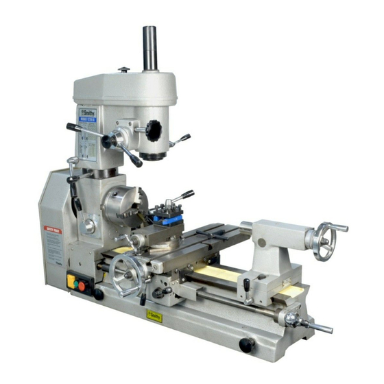
Summary of Contents for Smithy Midas 1220 XL
- Page 1 MIDAS 1220 XL COMBINATION LATHE/MILL/DRILL OPERATOR’S MANUAL Updated August, 2008 170 Aprill Dr., Ann Arbor, MI, USA 48103 Toll Free 1-800-476-4849 www.smithy.com...
- Page 2 While every precaution has been taken in the preparation of this manual, Smithy Co. shall not have any liability to any person or entity with respect to any loss or damage caused or alleged to be caused directly or indirectly by the instructions contained in this manual.
-
Page 3: Table Of Contents
Table of Contents ..........i-iv Inventory Check List . - Page 4 Chapter 8: Metalcutting Theory Tool Sharpness ......... . .8-2 Heat .
- Page 5 Chapter 13: Lathe Facing and Knurling Facing Across the Clutch ........13-1 Knurling .
- Page 7 By doing so, you can quickly determine if any parts are missing. In addition, should you find it necessary to return the machine to Smithy for any reason, the inventory will ensure that all the parts you received have been returned. It is also good to take a look at the inventory before you operate the machine so that you can be familiar with the names of all the parts of your Smithy machine.
- Page 8 Midas 1220 XL Operator’s Manual Gear, 42 Teeth Gear, 63 Teeth Item #: C30150 Item #: C30160 Quantity 1 Quantity 1 Gear, 45 Teeth Jaws (3), 5” Item #: C30156 Quantity 1 Item #: 9-10 Quantity 1 set of 3 Gear, 48 Teeth Item #: C30151 Key, Lathe Chuck...
- Page 9 Item #: 12-004 3/8 x 16 x 14” Quantity 1 Item #: 75-A Quantity 1 Cutting Fluid/ Tapping Item #: 49-101 Nut, 3/8 16 Quantity 1 Item #: 7-6 Quantity 1 Washer, Flat 5/16” Item #: 7-8 Quantity 1 Or Visit www.smithy.com...
- Page 10 If you find that an item is missing or defective from your Quick Start Tool Pack Call Us TOLL FREE 1-800-476-4849 or send an e-mail to info@smithy.com within 30 days of receiving your machine so that we may assist you immediately.
- Page 11 If you have comments about this operator's manual, or if you have a project you'd like to share with other Smithy owners, contact the Communications Director, Smithy Co., PO Box 1517, Ann Arbor, MI48106-1517.
- Page 12 Chapter 2 Safety Your workshop is only as safe as you make it. Take responsibility for the safety of all who use or visit it. This list of rules is by no means complete, and remembers that common sense is a must. 1.
- Page 13 14. Keep your mind on your work. Pay attention to these simple rules and you will spend many safe, enjoyable hours in your workshop. Remember: Your safety largely on your practices. Modifying your machine may void the warranty and create potential hazards. Or Visit www.smithy.com...
- Page 14 The middle position is neutral. Always shift the clutch with the motor turned off. The Smithy can use V-belts or round polyurethane belts. The latter produce less dust and is easier to change than standard V-belts.
- Page 15 Any rust spot or battering of the ways, any chips or grit between close fitting parts, will affect the accuracy of this fine tool. Follow these guidelines whenever you use your Smithy machine. When you finish working, wipe machined surfaces with a clean, oily rag. Never leave the machine without this thin film of protective oil over all parts that might rust, especially ground finished parts.
- Page 16 Chapter 5 Basic Parts of the MI-1220 XL To learn the operations of your machine, you have to know the names and functions of its basic parts. Figure 5.1 Basic parts of the MI-1220 XL 1. B e d - The Bed (Figure 5.1) is the machine's foundation. It is heavy, strong and built for absolute rigidity.
- Page 17 It also serves as the milling table. Gib Adjustment Screws Saddle Gib Adjustment Screw Cross Slide Lock Cross Slide Handwheel Figure 5.3 The cross slide moves laterally when you turn the cross slide handwheel. Or Visit www.smithy.com...
- Page 18 Midas 1220 XL Operator’s Manual 6. Drill Press and Fine Feed Clutch - Pushing in the drill-press clutch engages the fine feed. To work the clutch, release the spring tension by rotating the drill-press handles clockwise. Pull the clutch out to use it as a drill press or push it in to the fine feed. Use the fine-feed handwheel to move the quill up and down.
- Page 19 (two), Figure 5.1 and 5.7, keep them from moving. During machining, lock all lock except the one on the part you want to move. Figure 5.6 The quill moves in and out of the millhead, carrying the spindle. Or Visit www.smithy.com...
- Page 20 Midas 1220 XL Operator’s Manual 17. Micrometer Dial Collars - Just inside the handles of the tailstock (Figure5.1), crossfeed (Figure 5.1), drill press (Figure 5.1), compound feed (Figure 5.1), and leadscrew (Figure 5.1) there are collars calibrated in inches. The compound feed, leadscrew, and crossfeed are calibrated in two thousandths, the tailstock in thousandths, and the drill press in 40-thousandths.
- Page 21 Basic Parts of the MI-1220 XL Tailstock Setover Screw Tailstock Base- Locking Bolts Right Tresle Setscrew Figure 5.8 To offset the tailstock, adjust the base-locking bolts. Or Visit www.smithy.com...
-
Page 22: Chapter 6: Uncrating And Setting Up The Mi-1220 Xl
Moving a machine tool can be dangerous. Improper techniques and methods may injure you and/or damage the machine. To find a professional to move and site your Smithy machine to look in your local Yellow Pages under “Machine Tools, Moving and/or Rigging.”... -
Page 23: Millhead
Be careful not to lose them. Three-jaw Chuck 1. Remove the three bolts behind the chuck that hold it to the spindle flange (Figure 6.3). The chuck will come off. Place a board between the chuck and ways to protect the ways. Or Visit www.smithy.com... - Page 24 Midas 1220 XL Operator’s Manual Bolts Figure 6.3 The chuck attaches to the spindle flange with three bolts. The one bolt located on the other side of the spindle does not show. Put the machine on a strong, rigid table 40” long x 24” wide x 28 – 33” high. We recommend you bolt down the machine using the holes in the base of the bed or using the lifting handles the same way they held the machine to the shipping pallet.
-
Page 25: Selecting Location
Cleaning and Lubricating the Machine Smithy machines are shipped with a protective grease coating. To remove it, spray on WD-40, let it sit for a few minutes, and wipe it off with rags. Use a brush and noncorrosive kerosene or white mineral spirits to clean hard to reach places. -
Page 26: Oiling The Headstock
Midas 1220 XL Operator’s Manual Once it's cleaned, your Smithy is ready for lubricating. Do this carefully and thoroughly before starting the machine. Use pressure oil can and good quality SAE No. 20 or 30 weight machine oil on the bearings and headstock. -
Page 27: Oiling The Tailstock
Figure 6.8 Oil the two buttons on the top of the tailstock. Oiling the Apron 1. Put oil in the button just behind the cross-slide handwheel (Figure 6.7). 2. Put oil in the button at the back of the cross-slide (Figure 6.7). Or Visit www.smithy.com... -
Page 28: Oiling The Leadscrew
Midas 1220 XL Operator’s Manual Oiling the Leadscrew 1. Put oil in the oil buttons in the left trestle. 2. Put oil in the support for the right end of the leadscrew (figure 6.9). Figure 6.9 Oil the support for the right end of the leadscrew. 3. -
Page 29: Setting Up Your Mi-1220 Xl
For 125 rpm, place the mill belt in position A and the lathe belts in position C (Figure 6.12). For 160 rpm, place the mill belt in position B and the lathe belts in position C, etc. Or Visit www.smithy.com... -
Page 30: Adjusting Belt Tension
Midas 1220 XL Operator’s Manual A4 X B1 A3 X B1 A2 X B3 1250 3 2 1 B4 C1 B3 C1 B2 C3 A4 X B2 A2 X B1 A1 X B2 1600 B4 C2 B2 C1 B1 C2 A4 X B3 A3 X B2 A1 X B3... -
Page 31: Adjusting Gibs
Compound gib . The compound gib has two adjusting screws and jam nuts (Figure 5.3). For greater tool rigidity, you can adjust the compound gib a bit tighter that the others. 6-10 Or Visit www.smithy.com... -
Page 32: Reducing Backlash
3. Turn the handwheel one way, then the other. If a gap opens and closes between the dial and screw seat, you must install one or more shim washers (ask a Smithy technician about our antibacklash shim washer kit # K99-190) To install shims, remove the handwheel, key, washer and the outer part of the dial and spring. -
Page 33: Longfeed
Running In Though all Smithy machines are tested at the factory and again before shipping from the warehouse, it is wise to put your machine through a break-in run before starting to work. After oiling the machine, check the belts to make sure the tension is correct. Do not plug in the machine yet. - Page 34 Midas 1220 XL Operator’s Manual 3. Start the motor by pushing in on the green button. To reverse the motor, push the red button to stop it, lift the cover over the rocker switch, and push the rocker switch either up or down to reverse the motor's rotation.
-
Page 35: Chapter 7: Turning
2-1/4” 85 2-1/2” 76 2-3/4” 69 3” Table 7.1 Provides exact speeds (rpm). It does not make machine speed limitation into account. Determine the desired rate of speed and find the closest speed available on your machine. Or Visit www.smithy.com... - Page 36 Midas 1220 XL Operator’s Manual The modern lathe offers the following: • The strength to cut hard, tough materials • The means to apply power • The means to hold the cutting point tight • The means to regulate operating speed •...
-
Page 37: Gear Ratios
(tpi), replace the gears per Table 7.2. Threads Per Inch Metric Pitches Speeds Gear Position Speeds Gear Position .003 .006 0.50 1.00 0.60 0.70 0.75 1.50 0.80 1.75 1.00 2.00 1.25 2.50 1.50 3.00 Table 7.2 Gear Ratios Or Visit www.smithy.com... -
Page 38: Chapter 8: Metalcutting Theory
Chapter 8 Metalcutting Theory A machine tool is no more efficient than its cutting edge. Because lathe operations require continuous regrinding and resharpening of the machine's cutting tools, operators should know some metalcutting theory. All cutting with a sharp edge, whether with the thin blade of a knife or the almost square edge of a closely supported carbide tool, is basically a wedging-apart action. -
Page 39: Tool Sharpness
The Midas 1220 XL has a four-sided turret toolpost that accommodates up to four high-speed-steel (HSS), carbide-tipped, or indexable carbide turning tools. Or Visit www.smithy.com... -
Page 40: Heat
Midas 1220 XL Operator’s Manual Heat The energy expanded at the lathe's cutting point converts largely into heat, and because the energy is great, the heat is intense. Before today's HSS, carbide and ceramic tools, this heat created a serious machining problem. Machining could be done only under a steady flow of coolant, which kept the tool from heating to its annealing point, softening and breaking down. - Page 41 With the four-turret toolpost, you can install all standard-shaped turning and facing tools with 1” on smaller shanks. The centerline is approximately 5/8” above the bottom of the turret. Smithy also offers quick-change tool sets that greatly speed up lathe operations. Contact a Smithy technician for details.
-
Page 42: Chapter 9: Grinding Cutter Bits For Lathe Tools
Chapter 9 Grinding Cutter Bits for Lathe Tools High-Speed-Steel Cutters The advantage of HSS cutter bits is you can shape them to exact specifications through grinding. This lets you grind a stock shape into any form. Stock shapes come in an assortment of types, including squares, flats, and bevels. - Page 43 9.4. Cutter Bit Grinding Wheel 1. Left Side 2. Rigt Side 3. End 4. Radius 5. Top Rake Clearance Clearance Clearance Figure 9.3 Grinding sequence for an unground cutter bit. Or Visit www.smithy.com...
-
Page 44: Materials Other Than Steel
Midas 1220 XL Operator’s Manual Oilstone Figure 9.4 When honing, draw the cutter away from the cutting edge across the oilstone. Materials Other Than Steel As pointed out earlier, when grinding HSS cutters, we determine cutting angles primarily by strength requirements, not keenness requirements. Angles and rakes for general industrial shop use are established. -
Page 45: Bits For Turning And Machining Brass
V in a standard center gauge (Figure 9.8). Examine the gauge and cutter before a light. When the cutter is ground perfectly, no light streak shows between tool and gauge. Use a grinding chart for other rakes. Or Visit www.smithy.com... -
Page 46: Acme Or Other Special Threads
Midas 1220 XL Operator’s Manual Figure 9.8 Insert the point into the nearest seized V in the center gauge. Acme or Other Special Threads Thread gauges are available for all standard threads. Before grinding such cutters, ascertain the correct pitch angle of the particular thread profile. For example, the pitch of an acme thread is 29°... - Page 47 C-2* alloys Light finishing Precision boring 200 and 300 Series stainless steels Roughing cuts General Purpose C-6* Alloy steels Finishing cuts 400 Series stainless steel, high velocity Precision boring Table 9.1 Carbide Types and Cutting Tool Applications Or Visit www.smithy.com...
-
Page 48: Chapter 10: Setting Up Lathe Tools
Chapter 10 Setting Up Lathe Tools After selecting a cutter, insert it in the toolholder. Allow the cutter bit to project just enough to provide the necessary clearance for the cutting point. The closer the cutter is to the toolpost, the more rigid the cutting edge. Allen-head capscrews hold the tool in the toolpost. -
Page 49: Threading Tools
Note the tool is in the right-hand side of the toolpost. Threading Tools Threading tools should always engage the work on dead center. Any deviation above or below will affect the thread profile (Figure 10.4). Figure 10.4 Threading tools engage the work on dead center. 10-2 Or Visit www.smithy.com... -
Page 50: Cutoff, Thread Cutting And Facing Tools
Midas 1220 XL Operator’s Manual Cutoff, Thread Cutting and Facing Tools For cutoff, thread cutting, and facing, feed the cutter to the work on dead center (Figure 910.5). For the beginner, the average feed should not exceed 0.002 inches per revolution (ipr). -
Page 51: Chapter 11: Setting Up With Centers, Collets And Chucks
If you don't do this, a small tit or projection will remain in the center of the stock and perhaps cause the center drill to run off center. 4. Start your lathe on the slowest speed. Bring the tool into the cutting position against the center of the workpiece. 11-1 Or Visit www.smithy.com... -
Page 52: Centering A Round And Rectangular Steels
Midas 1220 XL Operator’s Manual 5. Feed the tool from the center of the stock outward, toward yourself, using the hand crossfeed. One or two light cuts is usually enough to true up an end roughened by the hacksaw. After facing one end, reverse the work and face the opposite end. Centering a Round and Rectangular Stocks 1.You can center on round stock (Figure 11.2) with calipers, dividers, or special centering instruments (Figure 11.3). - Page 53 Figure 11.7 Counterbore centers with a drill to a 60° point so they fit the lathe centers (A). Too obtuse (B) or too acute (C) a counterbore will give insufficient bearing and destroy the lathe centers. 11-3 Or Visit www.smithy.com...
-
Page 54: Mounting Work Between Centers
Midas 1220 XL Operator’s Manual Mounting Work Between Centers Remove the chuck from the lathe, bolt the faceplate to the spindle if l angle (Figure 11.8), and put in both headstock and tailstock centers. Fasten a lathe dog (Figure 11.9) to one end of the work. - Page 55 "throw" as the work revolves (Figure 11.11). Tail of Lathe Dog Figure11.10 Make sure the lathe dog tail is free in the faceplate slot so it won't lift off the true line of centers. Figure 11.11 Counterweights can help with unbalanced setups. 11-5 Or Visit www.smithy.com...
-
Page 56: Setting Up Work On Mandrel
Midas 1220 XL Operator’s Manual Setting Up Work on a Mandrel You can machine cylindrical or bored pipe work or cored castings too long to fit in a chuck by mounting them first on a mandrel (Figure 11.12). Then mount them between centers. The solid mandrels, which are driven into the hole of the work-piece, must be tight enough to turn the workpiece against the tool without slippage. - Page 57 Note: Take great care in adjusting the jaws of rests, as they must form a true axial bearing for the work and let it turn freely but without play. Figure 11.15 Follow rests mount on the lathe carriage and move with the tool. 11-7 Or Visit www.smithy.com...
-
Page 58: Setting Up Work In A Chuck
Midas 1220 XL Operator’s Manual Setting Up Work in a Chuck Chucks usually hold work that is too short to hold conveniently between centers or work requiring machining at, into (boring or inside threading), or across its end. While it is possible to set up such work on a faceplate, the convenience of chucks has made them part of every complete lathe. - Page 59 You can insert them with high steps to the inside or outside. Figure 11.18 For short, small-diameter workpieces, insert the jaws with high ends to the center. Figure 11.19 For large-diameter workpieces insert the jaws with high steps of the jaws to the outside. 11-9 Or Visit www.smithy.com...
-
Page 60: Mouting Work In A Three-Jaw Universal Chuck
Midas 1220 XL Operator’s Manual Caution Never leave the chuck key (wrench) in the chuck while the chuck is on the spindle. Any movement of the spindle can crash the key into the ways, seriously damaging the ways, spindle, and chuck. Turning on the lathe with the key in the chuck can seriously damage your lathe. -
Page 61: Collet And Collet Attachements
This is done by pulling the collet jaw's externally tapered shoulder into a matching taper-bored adapter sleeve. The adapter sleeve connects the lathe spindles MT5 taper to the collets MT3 taper. A drawbar holds the collet in place. 11-11 Or Visit www.smithy.com... -
Page 62: Toolpost Grinders
Midas 1220 XL Operator’s Manual Toolpost Grinders A fully equipped lathe has a toolpost grinder, a small, independently operated grinding head with an integral electric motor that mounts as a unit in the toolpost T-slot of the compound rest. (For lighter work, some are held in the toolpost.) You can maneuver it as you would any other cutting tool. -
Page 63: Chapter 12: Lathe Turning
If you zero the collar and watch the movement of the dial, you’ll know the depth of the feed from the zeroing point. Note: The dial gives a good approximation, but for exact measurements, use a measuring instrument. 12-1 Or Visit www.smithy.com... -
Page 64: Finish Turning
Midas 1220 XL Operator’s Manual To reduce the diameter, advance the tool only half as many thousandths on the dial. This is because the tool takes off an equal amount from both sides as it cuts a continuous strip around the work. For example, to reduce the diameter of a shaft 0.005”, you advance the tool only 0.0025”, or 1-1/4 calibrations. -
Page 65: Machining Square Corners
Use a clean, dry file and keep the workpiece clean, as well. Wipe the workpiece dry and clean if you’ve used coolant or cutting oil. Never hold the file stationary while the workpiece is revolving (Figure12.4). 12-3 Or Visit www.smithy.com... -
Page 66: Taper Turning
Midas 1220 XL Operator’s Manual Figure 12.4 With a file, take full strokes at an oblique angle and never hold the file still. For an even finer file finish, rub railroad chalk into its teeth. This provides additional lubrication and absorbs filings. Do not use blackboard chalk. After filing off the machining marks, polish the workpiece with emery or other abrasive cloth. - Page 67 Then multiply the resulting quotient by half the difference between the extreme diameters of the finished taper. 12-5 Or Visit www.smithy.com...
-
Page 68: Boring A Tapered Hole
Midas 1220 XL Operator’s Manual Figure 12.8 Tailstock set over should be half the difference between the finished diameters of the ends. That is 0=T” x L”/2 where T= taper per inch and L=length of work in inches. Note: (A) Because most drawings give the taper in inches per foot of length, it may be easier to convert all dimensions to inches. -
Page 69: Chapter 13: Lathe Facing And Knurling
If you must finish the ends of the shaft, use a half-center (Figure 13.2). This lets you extend the tool across the entire face of the work. To use the powerfeed for facing, place the speed selector into the desired position before 13-1 Or Visit www.smithy.com... -
Page 70: Knurling
Midas 1220 XL Operator’s Manual the lathe is turned on. Once the cutter has been positioned as per the above paragraph, move the crossfeed lever down. Pull the lever up at the end of the cut to stop the cutter travel. - Page 71 Feed both ways using the automatic longitudinal feed. Once across, each way, usually makes a good knurl. Figure 13.3 Feed the knurling tool at a slight angle off from perpendicular to the line of the work piece. 13-3 Or Visit www.smithy.com...
-
Page 72: Chapter 14: Changing Gears
Chapter 14 Changing Gears To change the gears on the MI-1220 XL, follow these steps. You will need a 10mm wrench, 6mm Allen wrench, screwdriver (to remove C clips), and pliers (to replace C clips). 1. Remove all C clips, nuts, and gears, starting with the A gear and ending with the D gear. - Page 73 You may need to make some adjustments. 10. Engage the E gear between the C and D gears to reverse the leadscrew (Figure 14.3). Figure 14.3 Engage the E gear between the C and D gears to reverse the leadscrew. 14-2 Or Visit www.smithy.com...
-
Page 74: Chapter 15: Cutting Screw Threads
Chapter 15 Cutting Screw Threads Threading Terms Before beginning to cut threads, it’s useful to learn the major terms used in thread cutting: Pitch. Metric pitch is the distance from the center of a thread to the center of the next thread. - Page 75 V of the gauge. Placing the threading tool perpendicular to the surface of the workpiece assures a true-form thread. Figure 15.2 With the compound perpendicular to the line of centers, Rotate it 29 degree to the right. 15-2 Or Visit www.smithy.com...
-
Page 76: Cutting Right Hand Threads
Midas 1220 XL Operator’s Manual Workpiece Center Gauge Toolbit 15.3 Using a center gauge, set the threading tool at exactly dead center on the workpiece. Cutting Right Hand Threads Now you are ready to cut right-hand threads, First, advance the tool so it just touches the workpiece and turn the compound calibration back to zero. -
Page 77: Cutting Left Hand Threads
Single Thread Double Thread Triple Thread Figure 15.5 When cutting multiple threads, increase the lead to make room for succeeding threads. 15-4 Or Visit www.smithy.com... -
Page 78: What Not To Do When Cutting Threads
Midas 1220 XL Operator’s Manual What Not To Do When Cutting Threads Do not disengage the half-nut lever. Do not shift the powerfeed speed lever. If you are cutting between centers don’t remove the lathe dog until the tread is finished and tested, and don’t disturb the spindle while the work is off the centers. -
Page 79: Chapter 16: Lathe Drilling And Boring
Use slow speeds and feed the reamer slowly and evenly into the workpiece. Be sure the reamer teeth are free of burrs and chips. 16-1 Or Visit www.smithy.com... -
Page 80: Boring
HSS cutter or carbide insert. There are many sizes and types of boring bars. Choose the one that will give the stiffest possible bar at every depth and diameter and the greatest choice of cutters and cutter angles (ask a Smithy technician about the Smithy boring head combo package, #K99-125). - Page 81 Figure 16.5 To machine ends of a bar, use a boring bar that angles the cutter so it extends beyond the bar. 16-3 Or Visit www.smithy.com...
-
Page 82: Cutting Internal Threads
Midas 1220 XL Operator’s Manual After the last finish cut, it is common to reverse the feed and take one last, fine cut with the tool coming out of the work. This last cut, taken without movement of the cross-feed, avoids a slightly undersized hole because you compensate for any spring in the bar. -
Page 83: Cutting Special Form Internal Threads
(Figure 16.8). If you don't have recommended clearances, it is safe to cut a nut thread (internal thread) 0.005" to 0.010" per inch larger in the screws outside diameter. Figure 16.8 Use different clearances between nut and screw for different thread types. 16-5 Or Visit www.smithy.com... -
Page 84: Chapter 17: Cutting Off Or Parting With A Lathe
Chapter 17 Cutting Off or Parting with a Lathe You can cut off in a lathe only when holding one end of the work rigidly, as in a chuck. It is not practical for long workpieces held between centers because the workpiece is not supported closely with a rest and the free section is long enough to sag and pinch the blade. -
Page 85: Chapter 18: Milling
To raise the millhead, turn it counterclockwise; to lower it, turn it clockwise. To rotate the millhead, release the lock lever and push the millhead to the desired position. 18-1 Or Visit www.smithy.com... -
Page 86: Chapter 19: Workholding
Chapter 19 Workholding The most common ways to hold a workpiece during milling are to secure it directly to the table via clamps or hold it in a vise (Figure 19.1). If you're making many similar workpieces, you may make a special fixture to hold them. Whatever method you use, hold the workpiece securely so it won't shift during machining and support it adequately to avoid swing. -
Page 87: Dividing Heads
You can buy sets of index plates for even more circumference divisions. Contact a Smithy technician for more information. Figure 19.3 Rotary tables let you cut gears, precision holes, and curved slots. -
Page 88: Chapter 20: Holding Milling Cutters
Chapter 20 Holding Milling Cutters There are several ways to hold milling cutters: in arbors, with collets and special holders, and in adapters. Arbors Arbors come in different sizes and lengths, with one end tapered to fit the bore in the end of the machine spindle. -
Page 89: Adaptors
For small cutters, Fit the shank of the arbour that carries the cutter directly into the taper hole at the end of the spindle. A drawbar holds the arbour in place. For large cutters, bolt the cutter directly to the end of the spindle. 20-2 Or Visit www.smithy.com... -
Page 90: Chapter 21: Milling Cutters
Chapter 21 Milling Cutters Choose milling cutters for the type of cut, the number of parts, and the material. Rake angles depend on both cutter and work material. Clearance angles range from 3° to 6° for hard or tough materials to 6° to 12° for soft materials. To determine the number of teeth you want, consider the following: •... - Page 91 • Face milling cutters start in size at 2" and have inserted teeth the periphery and face. Most of the cutting takes place on the periphery. They are similar to, but larger than, shell end mills. 21-2 Or Visit www.smithy.com...
-
Page 92: Plain Milling Cutters
Midas 1220 XL Operator’s Manual Plain Milling Cutters Plain milling cutters have teeth only on their periphery. Used to mill plain, flat surfaces, they may combine with other cutters to produce various shapes. They are cylindrical and come in many widths and diameters. •... - Page 93 With one or more single-point toolbits or cutters, flycutters (Figure 21.5) perform end milling even though they're not end mills. They take light face cuts from large surface areas. You must grind the toolbit properly to get correct rake and clearance angles. Grind 21-4 Or Visit www.smithy.com...
- Page 94 Midas 1220 XL Operator’s Manual toolbits for flycutters as you grind lathe tools (Section Seven). You can also use flycutters for boring. Note: When the tool revolves, the cutting tool becomes almost invisible, so be careful. Figure 21.5 Flycutters take light face cuts from large surface areas. Using Cutting Fluid Cutting fluids get rid of heat generated by the friction of the milling cutter against the workpiece.
- Page 95 You sharpen others by grinding the front faces of their teeth. Formed or relieved cutters, for example, have profiles that must be preserved. This category includes all sorts of formed cutters as well as cutters used for milling various regular and irregular shapes. 21-6 Or Visit www.smithy.com...
- Page 96 Chapter 22 Speeds and Feeds for Milling Speeds Milling cutting rates vary according to the machinability of the material being cut; whether cutting fluid is used and, if so, what kind; the type, size and material of the cutter and the coarseness of its teeth;...
- Page 97 Figure 22.1 In up milling (left), the workpiece feeds into the cutter in the opposite direction of the cutter’s revolutions. In down milling (right), the workpiece feeds into the cutter in the same direction as the cutter is turning. 22-2 Or Visit www.smithy.com...
- Page 98 Midas 1220 XL Operator’s Manual Brinell High-Speed-Steel Carbide Material Hardness Cutters Cutters 100-150 120-160 400-600 Free-machining low carbon 1111 150-200 120-180 400-900 steel resulphurized 1112 100-150 100-225 250-500 Free-machining low carbon 10L18 150-220 110-250 250-600 steel leaded 12L14 100-125 80-150 300-600 Plain low-carbon steels1006 125-175...
- Page 99 Another way to mill flat surfaces is by face milling. In this method, the cutter teeth operate at right angles to the cutter axis. Inserted-tooth face-milling cutters (Figure 23.2) face mill large surfaces. Figure 23.2 Inserted tooth face milling cutters face mill large surfaces. 23-1 Or Visit www.smithy.com...
- Page 100 Midas 1220 XL Operator’s Manual Bevels and chamfers are cut at an angle to the main work-piece surface. A bevel cut (Figure 23.3) goes from side to side, completely removing the perpendicular edge. A chamfer removes only part of the perpendicular edge. Figure 23.3 A bevel cut goes from side to side, completely removing the perpendicular edge.
- Page 101 Remove the screw at the bottom of the bevel gear (Figure 24.2) and pull the gear from the shaft. Then reassemble it with the new gear. Before placing the millhead, adjust the bevel gear so it won’t break as tighten the millhead onto the lathe head. Then adjust the bevel gear. 24-1 Or Visit www.smithy.com...
- Page 102 Midas 1220 XL Operator’s Manual Figure 24.2 Remove the screw at the bottom of the bevel gear. Millhead T-Key The millhead has a T-key between the drive shaft and drive pulley. If you raise the millhead more than usual, this key may come partly or completely out. If it is out only partially, raise the millhead slightly.
- Page 103 Figure 24.4 Bend back the tab on the lockwasher and remove the spanner nut and lockwasher. Figure 24.5 Pull on the clutch sleeve to remove the left jaw clutch and entire clutch assembly from the lathe spindle. Figure 24.6 Remove the shaft sleeve from the spindle. 24-3 Or Visit www.smithy.com...
-
Page 104: Troubleshooting
Chapter 25 Troubleshooting Powerfeed and Thread Cutting Powerfeed does not move carriage Cause Solution • Carriage locked • Unlock carriage • Speed selector not engaged • Select speed I or II • Sheared pin • Replace pin • Gears not meshing or teeth missing •... - Page 105 • Reposition wiper(s) Cross-slide handwheel turns during cutting operations Cause Solution • Cross-slide brass nut worn • Tighten or replace brass nut • Carriage locks not tight • Tighten carriage locks • Gibs to loose • Readjust gibs 25-2 Or Visit www.smithy.com...
- Page 106 Midas 1220 XL Operator’s Manual Too much backlash in the cross-slide Cause Solution • Loose screw • Tighten screw, review how to eliminate backlash • Loose brass nut • Put a shim between the stud on the nut and the side of the hole •...
- Page 107 • Gibs too loose on cross slide, compound • Readjust gibs or carriage • Unused feeds not locked • Lock all axes but the one moving • Millhead not locked • Lock millhead • Quill too loose • Tighten quill lock 25-4 Or Visit www.smithy.com...
- Page 108 Midas 1220 XL Operator’s Manual • Tool not on center • Center tool • Improper tool shape, tool dull • Reshape, sharpen or replace tool Depth of cut is not consistent Cause Solution • Quill moving • Lock quill • Setup wrong •...
- Page 109 Pulleys turn and clutch is engaged but the mill does not turn Cause Solution • T-key missing • Replace key • Bevel gears stripped or broken • Replace bevel gear • Bevel gear out of adjustment • Readjust bevel gear 25-6 Or Visit www.smithy.com...
- Page 110 Chapter 26 MI-1220 XL Specifications General Dimensions Length 42” Width 20” Height 37” Shipping Weight 530 lbs Machine Weight 419 lbs Crate Size 43-1/2” x 22-1/2” x 36-1/4” Footprint 42” x 30” T-Slot Size 7/16” Accuracy +/- 0.001” Powerfeed (X-Axis) Powerfeed (Y-Axis) Powerfeed (Z-Axis) Table Size...
- Page 111 Spindle to Table Distance(min-max) 6-1/4” - 13” Spindle Speeds 12 (125-1600 rpm) Spindle Taper Tool Size Limits 1” X-Axis Travel 6-5/8” Y-Axis Travel 7-3/8” Electrical Amperage 11 amps Horsepower 3/4 hp Motor Type Phase Single Voltage 110 Volts A/C 26-2 Or Visit www.smithy.com...
- Page 112 Chapter 27 Removing the Apron from the MI-1220 XL Please have the manual at hand when working on the machine and when calling Smithy Co. for assistance. The apron is removed with the leadscrew still installed in the apron. This prevents the worm gear inside the apron from falling out off place.
- Page 113 Chapter 28 Changing the Lateral Drive Shaft in the MI-1220 XL Apron Please have the manual at hand while working on the machine and when calling Smithy Co. for assistance. Procedure: 1. Remove the apron and leadscrew as per instructions from Chapter 27.
- Page 114 Machine Warranty 30 Day Trial Offer Try a Smithy for 30 days. If, for any reason within that time, you decide to return your Smithy, just call our Customer Service department at 1-800-476-4849. We will help you arrange shipping back to us. When we receive the machine back, we’ll refund your full purchase price.
- Page 115 This is Smithy Co.’s sole warranty and any and all warranties that may be implied by law, including any merchantability or fitness, for any particular purpose, are hereby limited to the duration of this written warranty.
Need help?
Do you have a question about the Midas 1220 XL and is the answer not in the manual?
Questions and answers