Table of Contents
Advertisement
Quick Links
Advertisement
Table of Contents

Subscribe to Our Youtube Channel
Related Manuals for Smithy MI-1440L


Summary of Contents for Smithy MI-1440L
- Page 1 MI-1440L OPERATOR'S MANUAL...
- Page 2 While every precaution has been taken in the preparation of this manual, Smithy Ind. shall not have any liability to any person or entity with respect to any loss or damage caused or alleged to be caused directly or indirectly by the instructions contained in this manual.
-
Page 3: Table Of Contents
-Shop Safety Rules -Machine Operation Safety Rules Chapter 3: Machine Specifications Chapter 4: Inventory Check List a-Overview b-Smithy Quick Start Pack, Check List c-Missing Items Chapter 5: Machine Overview -Overview -Major Components and Controls Chapter 6: Setting Up Your Machine... - Page 4 Chapter 7: Preparing Your Machine for Operation -Overview -Cleaning & Lubrication -Gib Adjustment Chapter 8: Lathe Operations Simple instructions for Operating the Machine -Power the machine on -Spindle operations -Changing spindle speeds Chapter 9: Powerfeeding -Speeds & Feeds Defined -Setting Spindle Speeds -Setting Feed Rates -Power feed engagement Chapter 10: Threading operation...
-
Page 5: Chapter 1: Introduction
Introduction Welcome To the manual for the Smithy MI-1440L lathe. It will teach you about the parts of the machine and how to take care of your investment. This manual is complete and current at the time of printing*. In our continuing effort to bring you the best in machine tools, changes may be made - please visit us at www.smithy.com for the latest updates. - Page 6 Smithy owners, contact Smithy Industries, P.O. Box 1517, Ann Arbor, MI 48106-1517. You can also send an e-mail to: info@smithy.com Questions? If you have questions not covered in the manuals, please call our toll-free...
-
Page 7: Chapter 2: Safety
Chapter 2 Safety Overview Smithy machines are proven to be safe and reliable; however, if abused or operated improperly, any machine can cause injury. Please read this manual carefully before you start machining. Proper use will create a safe working environment and prolong the life of your machine. -
Page 8: Shop Safety Rules
This list of rules is by no means complete, so remember that common sense is a must. DANGER Smithy strongly discourages the use of casters or wheels on metal-working machine benches. The weight of the machine could result in the bench tipping while being moved. - Page 9 machine while it is in use. Childproof your shop with padlocks, master switches, and starter keys or store the machine where children do not have access to it. 6. Never operate your machine under the influence of drugs and alcohol. 7.
- Page 10 5. Secure your work. Before starting your machine, be certain that your work piece is properly and securely mounted. Flying metal is dangerous! 6. Do not run you machine beyond its limits of travel. Before starting your project, ensure that your work area does not go beyond the limits of travel on your machine.
-
Page 11: Chapter 3: Machine Specifications
Chapter 3 MACHINE SPECIFICATIONS – MI-1440L LATHE ELECTRICAL SPECIFICATIONS Power Requirements 110 or 220V, Single Phase, 60 Hz Phase Single Plug NEMA 515P (Included) Outlet NEMA 515R (Outlet Not Included) Connection Type Plug & Cord Horse Power Motor Voltage 110 or 220V Motor Amperage 18 Amps (110) 9 Amps (220) Motor Type A/C Constant Speed Induction PRODUCT DIMENSIONS Machine Weight 1340 lbs. Machine Length 70” Machine Height 32” Machine Width 30” Shipping Weight 1500 lbs. Shipping Length 76” Shipping Width 30”... - Page 12 Dial Calibration on Longfeed .01” Dial Calibration on Crossfeed .002” Dial Calibration on Tailstock .001” Dial Calibration on Toolpost .001” Powerfeed ZAxis in/r .002”.055”/ rev Powerfeed XAxis in/r .0002”.019”/ rev Oiled Gear Boxes Lathe Chuck Diameter 8” Lathe Chuck Min Diameter Workpiece 1/8” Lathe Chuck Max Diameter Workpiece 8” Lathe Chuck Type 3 Jaw & 4 Jaw Lathe Chuck Mount D15 Spindle Bore 2” Swing Over Worktable 7.5” Swing Over Bed 14” Swing w/Gap Removed 18.75” Spindle Accuracy TIR .0003” Tailstock Barrel Travel 4” Tailstock Taper Tailstock Offset 3/8” Threads (Inch) 456 TPI Threads (Metric) .47mm Tool size...
-
Page 13: Chapter 4: Inventory Check List
A third reason to perform an inventory is to become familiar with the names of all of the parts of your Smithy machine. Items Included With Your Machine The items listed below are shipped in the same crate as your MI-1440L Lathe. Please check if the following items are present: 83-945 Owner’s Manual... -
Page 14: C-Missing Items
If you find that an item is missing or defective from your Quick Start Tool Pack Call TOLL FREE 1-800-476-4849 send e-mail info@smithy.com within 30 days of receiving your machine so that we may assist you immediately. Our sales and service technicians are available 9am to 5:30pm ET, Monday through Friday. -
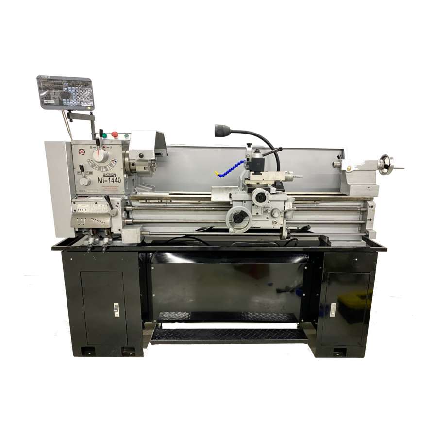
Page 15: Overview
Chapter 5 Machine Overview Overview This chapter will help you to familiarize yourself with the Smithy MI-1440 Lathe. The figure below identifies the major controls for your machine. 14 15 & 17 16 1. E-Stop and start button 2. Machine on indicator 3. - Page 16 8. Longitudinal feed hand wheel 9. Tool Post handle 10. Toolpost feed handle 11. Powerfeed engagement selectors 12. Threading half nut 13. Spindle forward/reverse selectors 14. Threading dial 15 & 17. Tail stock locks on back side of tail stock 16.
- Page 17 Long Feed Handwheel Turning this handwheel moves the entire crossfeed assembly left and right. This is used for positioning and manual cutting. 9 Tool Post Handle This revolves the tool turret in to 4 different positions. 10 Tool Post Feed Handwheel This moves only the upper part of the compound angle too post.
-
Page 18: Chapter 6: Setting Up Your Machine
Moving a machine tool can be dangerous. Improper techniques and methods may injure you and/or damage the machine. To find a professional to move and site your Smithy machine to look in your local Yellow Pages under “Machine Tools, Moving and/or Rigging.” If there is no such listing or your community does not have a rigging specialist, a local machine shop or machinist may be able to provide a referral. -
Page 19: Lifting Your Machine & Placing It On A Stand
Lifting Your Machine & Placing it On the Stand Once you have found a suitable location for your new lathe, you will need a mechanical lifting device, such as a engine hoist or fork lift, to remove the machine from the pallet and to place it on the stand. Remove the bolts, securing the machine to the pallet and any loose boxes or parts that may fall off the machine while moving it. -
Page 20: Power Requirements
It is recommended to connect to a 20 amp dedicated 110 VAC circuit. Check your local electrical codes for details on the supply circuit. The machine can be changed to 220 volt. Contact smithy for more information. Leveling the Machine Leveling of a machine tool is not making the machine level to the horizontal plane. - Page 21 Place a precision level across the bed of the machine close to the lathe chuck. Note the bubble position on the level. Move the level to the tailstock end of the machine. The bubble position should be the same as at the chuck end of the machine.
- Page 22 Give special attention to the lead screw. Use a brush or cotton string to clean down into the threads. Once it's cleaned, your Smithy is ready for lubricating. Do this carefully and thoroughly before starting the machine. The lathe head has an oil site gauge.
- Page 23 The apron has an oil reservoir. Oil is squirted one of the apron attach screw holes. It will run down into the apron. Oil should be half way up the site gauge on the front of the apron. The quick change gearbox is oiled by removing the plug shown below and squirting oil into the opening.
- Page 24 There are oil buttons located in numerous locations on the carriage, table, tool post and tail stock. These should be oiled on a daily basis. A 30 weight non-detergent oil is recommended. When the machine is not in use, it is recommended that a thin coat of oil be applied to all exposed metal parts to protect the surfaces from corrosion.
- Page 25 Adjusting the Gibs The objective of adjusting the gibs is to eliminate as much play in the X and Z axis as possible without having the tightness of the gib interfere with their movement and cause a decrease in the accuracy and performance of the machine due to excessive friction.
- Page 26 X Axis Gib Adjustment There are also two adjustment screws. One in the front and the other one on the back of the cross slide which is shown in the images below. 1. To tighten the gib, loosen the rear screw about 2 turns. Slowly tighten the front screw while moving the cross feed fore and aft.
- Page 27 Removal And Installation Of Lathe Chuck And Faceplate The spindle nose and chuck mounting is a D1-5 Type. This is one of the industry standard mounts and makes it possible to mount numerous styles and types of chucks to your machine. The chuck is attached to the spindle nose by 5 cam locks and studs.
- Page 28 Chapter 8 Lathe Operations Overview The MI-1440L lathe is put through a initial run-in procedure at the factory before the machine is packaged for shipment. 1. Once you have your lathe setup, Smithy recommends that the spindle motor be run for about 5 minutes at each of the spindle speeds starting with the slowest speed.
- Page 29 Spindle Operation 1. Once the desired speed is selected, move the Motor Engagement Lever downward to run in the forward direction for normal turning and threading operations. 2. Move the Motor Engagement Lever back to the center position to stop the lathe spindle.
- Page 30 Chapter 9 Powerfeeding Overview There are several steps to set up for using the power feed. Determining the proper feed rate for a specific material and size of workpiece will require the use of reference guides such as Machinery's Handbook or Machinist Ready Reference .
- Page 31 “a” LONG FEED 120 t INCHES PER ONE SPINDLE REVOLUTION 60 T “a” LEVER .0548 .0512 .0411 .0328 .0274 .0256 .0205 .0164 .0274 .0256 .0205 .0164 .0137 .0128 .0102 .0082 .0137 .0128 .0102 .0082 .0069 .0064 .0051 .0041 .0069 .0064 .0051 .0041...
- Page 32 The Powerfeed engagement lever allows you to start the powerfeed for either the longitudinal direction or the cross feed direction. Moving this lever to the left and up will activate the power longitudinal feed. Moving the lever to the right and down will activate the power crossfeed.
- Page 33 CHAPTER 10 Threading operation Overview This lathe is capable of cutting imperial or metric threads. There are gears on the end of the machine under the belt cover that will need to be changed for cutting some metric threads. Half Nut Lever This lever compresses and releases the half nut that engages the leadscrew.
- Page 34 See the chart below shows the engagement numbers that can be used on inch threads. NOTE: The thread dial can be used on inch threads only, Metric threads require all mechanical connections remain intact throughout the entire threading procedure. Thread chart Inch The thread chart is used in the same manner as the feed rate charts.
- Page 35 To set up for 24 threads per inch: 1. Place the 56 tooth gear in the “a” position and the 54 tooth gear in the “b” position. 2. Mesh both “b” and “a” to the 127 tooth gear. 3. Place the A-B selector in “A”, the C-D selector in “C”, the T-S-R-V selector in “V”...
- Page 36 Setup and cutting metric threads 1.Open the pulley cover on the left end of the machine. 2.Loosen the bolt at the pivot point of the gear quadrant and the nut at the quadrant slot. 3.Loosen the nut at the center gear. 4.Remove the lower gear and install the required gear but turn it around so when it is installed, it will mesh with the...
- Page 37 Do not disengage the halfnut until the thread is finished. All mechanical connections must stay intact for metric threads. If the thread is to be cut in multiple passes, 12.Turn the spindle off with the motor fwd/rev lever. 13.Back the cutter away from the workpiece. 14.Reverse the spindle motor and power back to the start of the tread.
- Page 38 Installation 1. Place the chuck onto the end of the spindle and turn the cams clockwise. Rotate each cam enough to hold the chuck in place but do not tighten yet. When all 3 of the cams are engaged, go back and tighten each one.
- Page 39 Follow Rest The follow rest is designed to support behind a small part to keep it from flexing away from the cutter during turning operations. The follow rest mounts on the left side of the carriage as shown below. The supports are adjusted before each pass since the material is getting smaller with each pass.
- Page 41 Bed & Motor Assembly Part Part Item Item Description Qty. Description Qty. Number Number Screw, socket head cap M10 x S12104 S18125 Nut M8 LZ01024 Brake ring LZ01003 Pin, taper pull type M8x75 LZ01025 Spring, coil 1x6x25 LZ01004 Gap bed section LZ01026 Bracket LZ01005...
- Page 43 Part Part Item Item Description Qty. Description Qty. Number Number Screw, socked head cap S11971 LZ02030 Gear M6x16 MLZ02002 Screw, oil fill S21380 Key, square M5x50 LZ02003 Cover plate Gear MLZ02004 Gasket MLZ02033 Casting, headstock S11938 Screw, set flat point M6x8 S18125 Nut, hex LZ02006...
- Page 44 Part Part Item Item Description Qty. Description Qty. Number Number MLZ02058 Cover, rear S21110 Key, square M4x14 Screw, socked head cap S12011 LZ02092 O-ring 13.8x3.1 M6x25 LZ02060 Screw, short LZ02093 Washer MLZ02061 Nut, spanner M62x2 LZ02094 Seal, oil 24x32x5 LZ02062 Nut, locking LZ02095 Gear...
- Page 46 Gearbox Assembly Part Part Item Description Item Description Item Qty. Number Number Not Used LZ04019 Gasket Not Used S20180 Bearing, ball 6203 17x40x12 Screw, socket head cap S11971 LZ04021 Cover M6x16 LZ04004 Washer S23010 Snap ring, external M16 LZ04005A Gear, change 30T LZ04023 Gear, duplex 24T &...
- Page 47 Gearbox Assembly Continued Part Part Item Description Qty. Item Description Qty. Number Number LZ04054 Seal, oil 28x40x7 LZ04074 Engaging arm S21260 Key, square 5x20 LZ04075 Screw, cheese head LZ04056 Shaft LZ04076 Switch, micro LZ04057 Gear 32T LZ04077 Plate LZ04058 Cover LZ04078 Gear 30T LZ04059...
- Page 49 Apron Assembly Part Part Item Item Description Qty. Description Qty. Number Number LZ05001 Bolt, hex head M6x10 S11612 Screw, set cone point M5x6 LZ05002 Washer LZ05024 Dial LZ05003 Gear LZ05025 Handwheel S21512 Key, square M5x12 LZ05026 Washer Screw, socket head cap LZ05005 Shaft S11971...
- Page 50 Apron Assembly Continued Part Part Item Item Description Qty. Description Qty. Number Number LZ05044 Bushing S18065 Nut, hex M5 LZ05045 Pin, straight 3x25 LZ05068 Screw, set flat point M5x16 LZ05046 Gear 40T LZ05069 S13512 Screw, set flat point M5x12 LZ05070 Pin, straight 6x12 LZ05048 Gear 30T...
- Page 52 Saddle and Cross Slide Assembly Part Part Item Item Description Qty. Description Qty. Number Number LZ06001 Handle M8x 63 LZ06025 Sleeve LZ06002 Screw S21170 Key, square M4x20 LZ06003 Washer LZ06027 Gear shaft LZ06004 Handle wheel S02283 Screw, flat head M3x6 LZ06005 Dial ring LZ06029...
- Page 54 Toolpost Assembly Part Item Description Qty. Number LZ07001 Knob 10x50 LZ07002 Handle rod 10x80 LZ07003 Handle seat LZ07004 Washer LZ07005 Screw, turret M8x40 LZ07006 Turret LZ07007 Stud, turret S11942 Screw, set cone point M6x10 LZ07009 Stop LZ07010 Spring, coil .4x4x18 LZ07011 Top slide C30050...
- Page 56 Tailstock Assembly Part Item Description Qty. Number LZ07001 Base LZ07002 Screw, base locking LZ07003 Collar, eccentric S22240 Pin, spring M5x25 S18125 Nut,plain M8 S12332 Screw, set dog point M8x35 LZ07007 Shaft LZ07009 Knob M15x50 LZ07009 Handle shaft LZ07010 Knob M8x40 LZ07011 Handle shaft LZ07012...
- Page 58 Electrical System Components Part Item Description Qty. Number LZ09009 Contactor LX06016 Aux Contactor LZ09016 Transformer LZ09019 Contactor LX06045 Jog button LX06042 E-Stop button LX06040 Indicator light Z40204 Fuse only LZG10012 Direction switch, rotary type Direction switch, micro switch Z40201 type LZ01042C Motor, 110/220 not shown...
Need help?
Do you have a question about the MI-1440L and is the answer not in the manual?
Questions and answers