Table of Contents
Advertisement
Advertisement
Table of Contents

Related Manuals for BSS Audio Omnidrive FDS-388


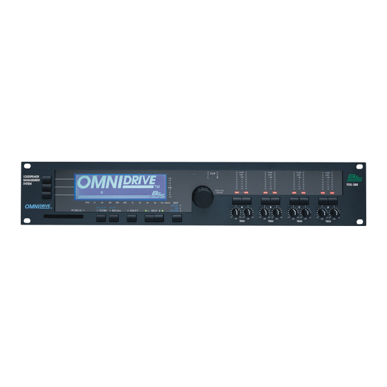
Summary of Contents for BSS Audio Omnidrive FDS-388
- Page 2 IT SHOULD NOT BE NECESSARY TO REMOVE ANY PROTECTIVE EARTH OR SIGNAL CABLE SHIELD CONNECTIONS TO PREVENT GROUND LOOPS. ANY SUCH DISCONNECTIONS ARE OUTSIDE THE RECOMMENDED PRACTISE OF BSS AUDIO AND WILL RENDER ANY EMC OR SAFETY CERTIFICATION VOID. For continued compliance with international EMC legislation ensure that all input and output cables are wired with the cable screen connected to Pin 1 of the XLR connectors and/or the jack plug sleeve.
- Page 3 Quick Start Quick Reference Quick Start - Quick Reference Check the Mains Voltage setting on the rear of the FDS-388/380 Omnidrive and install into a rack. Connect the mains to the unit and check that it powers up. Connect the two audio inputs and up to eight audio outputs. Do not put any audio through the unit at this time.
- Page 4 Please Read This! Using This Manual Please Read This! - Using This Manual This manual has been written to make the understanding and operation of the FDS-388 Omnidrive as easy as possible. Because the Omnidrive is a relatively sophisticated software product, we have included several ways to find the information you require in this manual.
-
Page 5: Table Of Contents
Contents Contents Introduction Other features OMNIDRIVE TM Loudspeaker Management System Installation Unpacking Mechanical Requirements Mains Power Voltage Setting Safety Earthing AC Power Fusing Rear panel Controls Output Section Getting Around the FDS-388 Default Screen Default Utility Screen Delay Screen Delay Utility Screen EQ Screen 10.0 EQ Utility Screen... - Page 6 Contents 16.0 Recall Screen 17.0 File Utility Screen 18.0 PCMCIA Card 18.2 Smart Card Format 18.1 Card Types 19.0 System Security 19.1 Program Lock 19.2 Lock Mode On 19.3 OWNER Lock 19.4 OEM Lock 19.5 Safe 19.6 OEM Hide Screen 20.0 Meteorology 21.0...
-
Page 7: Introduction
Introduction Introduction The OMNIDRIVE system represents a radical step forward in DSP processing 1.1 OMNIDRIVE for loudspeaker management, incorporating BSS’s vast experience in crossover Loudspeaker design and combining two channels of 4-way crossover, parametric Management equalisation, digital delay lines and limiters, and is designed for use in all areas of sound control. -
Page 8: Installation
Mechanical Requirements Installation 2.1 Unpacking As part of BSS Audio Ltd’s policy of quality control, this product is carefully checked before packing to ensure flawless appearance and that it reaches you in first class condition. After unpacking the unit, please inspect it for any physical damage. If any damage has occurred, notify your dealer immediately. -
Page 9: Mains Power
Mains Power Voltage Setting Refer to Section 2.6 'Installation' - AC Power and Fusing. 2.3 Mains Power WARNING! THIS APPLIANCE MUST BE EARTHED. IMPORTANT: The wires in the mains lead are colour coded in accordance with the following code. Green and Yellow..Earth Blue..Neutral Brown..Live As the colours of the wires in the mains lead may not correspond with... -
Page 10: Safety Earthing
Safety Earthing AC Power Fusing 2.5 Safety Earthing The Green and Yellow wire of the mains cord must always be connected to an installation Safety Earth or Ground. The Earth is essential for personal safety as well as the correct operation of the system, and is internally connected to all exposed metal surfaces. -
Page 11: Rear Panel
Rear panel 2.7 Rear panel Mains power input Fuse Power voltage selector Meteorology probe connector Refer to Section 20.0 Meteorology and Section 8.0 Delay Utils Screen. 8 Band outputs The FDS-388 audio outputs are electronically balanced and floating. Transformer balancing is available as a retrofit option. Pin 1 Shield/Ground Pin2... -
Page 12: Controls
Controls Controls Fig 3.1 Front panel Soft Keys Many of the editing screens have one or more soft key labels down the left hand side of the display (Fig 3.2). Each corresponds to one of the three soft keys. The soft keys are most often used to select a type of parameter. The individual parameter to adjust is selected by pushing the encoder. -
Page 13: Edit Key
Controls Utility Key The Utility Key takes the user in and out of each edit screen's utility area. The led is lit when in a utility screen. Refer to Section 4.0 Getting Around Left/Right/Split Keys These keys control which channel or channels the user is adjusting and which channel is viewed. -
Page 14: Output Section
Output Section 3.1 Output Section Fig 3.2 Output Section Mono led The Mono led reflects the status of the Mono Lo parameter which is set in the XOver Utility Screen. Refer to Section 12.0, XOver Utility Screen - Mono Lo When the led is on, the left and right A bands are summed to produce a mono output. -
Page 15: Getting Around The Fds-388
Getting Around the FDS-388 Split, Left and Right Keys Getting Around the FDS-388 4.1 Split, Left and The Split keys (Left and Right) are used to select which of the two channels in the FDS-388 is being displayed and whether the user wishes to control one or Right Keys both of the channels simultaneously. - Page 16 Moving Around the Screens Fig 4.0 FDS-388 Key 4.2 Moving Around Quick Reference the Screens Pressing the EDIT key shifts the screen through each of the main editing areas in turn and then back to the main ‘Default’ screen. Pressing and holding the EDIT key will take the user back to the main ‘Default’...
- Page 17 Moving Around the Screens The Soft keys have different operations depending on the cur- rent screen. Two lines of text for each key on the left hand side of the screen label the key’s function. Turn the encoder knob to adjust the currently selected variable. Press the encoder knob or press and turn the encoder knob to move between the available variables.
- Page 18 The Edit Key The Utility Key After powering up, the FDS-388 performs internal checks and sets up the audio path before releasing the output mute relays. The time before the mute relays open can be set in the Default Utility screen. Refer to Section 6.0, Default Utility Screen.
- Page 19 The Soft Keys and Encoder Store and Recall The Xover Utility Screen sets the master slope (in dB per octave) and the shape (Linkwitz-Riley, Butterworth or Bessel) for all crossover edges. Mono low on and off, and the units for the limiter values are also set here. Pressing the Top Soft key in the Xover Utility screen takes the user to the Xover More screen.
-
Page 20: Default Screen
Default Screen Default Screen Program number Swap status Edited flag OEM name Program name Status Band response curves Humidity correction Quick Reference Press the EDIT key to enter the edit screens. Press STORE or RECALL for the file handling screens. When the FDS-388 is powered up the Default screen is shown. - Page 21 Default Screen The current program number is shown in the top left corner of the screen. The program number is displayed with double size digits until the values have been edited and so differ from the last recalled or stored program. Once edited, the program number is displayed with normal size text.
-
Page 22: Default Utility Screen
Default Utility Screen Default Utility Screen Quick Reference Press the parameter wheel to move between utilities. Turn the parameter wheel to adjust the value. Backlight Dim,Low,Mid,High This utility adjusts the brightness of the screen backlight View angle This utility adjusts the viewing angle of the lcd display. Midi Chan 1 to 16 This sets the Midi channel to which the unit sends and responds. - Page 23 Default Utility Screen system designer. If the password is entered correctly, the middle soft key will allow the user to enter the OEM Hide Screen. If the password is incorrect, the Lock Mode returns to off. If the user wishes to create a new program and lock areas using OEM hide then they should begin by recalling the default program (program 0) or another program which is not OEM locked.
-
Page 24: Delay Screen
Delay Screen Delay Screen Soft key titles Main delay Delay units Band names Phase adjust Listening position Band delay representations Band polarity Main delay reference line Band delays Quick Reference To adjust the overall delay for all four bands press the top soft key and turn the parameter wheel To adjust the delay for an individual band press the middle soft key, press the encoder to select a band and turn the... - Page 25 Delay Screen Top Soft Key Selecting the top soft key allows the user to adjust the overall delay of all four outputs. Alongside the Main Delay value are the units used to display both the Main and Band Delay values. The units can be changed in the Delay Utility MAIN DELAY screen.
-
Page 26: Delay Utility Screen
Delay Utility Screen Delay Utility Screen Quick Reference Press the parameter wheel to move between utilities. Turn the parameter wheel to adjust the value. Delay Units ms, ft, m This selects the units used for displaying and adjusting both main and band delays on the Delay Screen. - Page 27 Delay Utility Screen Note that changing this parameter can cause delay times to shift slightly. If temperature correction is to be used the temperature probe should be plugged in and this mode set to On at the time that the delays are set up. Humidity Adjustable 0 to 100% This is the current percent relative humidity used to correct the high frequency...
-
Page 28: Eq Screen
EQ Screen EQ Screen Frequency Filter band and number Swap status OEM name Band name Program number Edited flag Program name Bandwidth or Cursor Combined EQ and Full bandwidth curve shelf shape crossover curve Cut/boost Filter marker Quick Reference Press the parameter wheel to select a filter to adjust. Press the top soft key and turn the parameter wheel to adjust the filter frequency. - Page 29 EQ Screen At the bottom of the screen the small arrowheads indicate the filter frequencies in the current band. A solid arrowhead and a dotted vertical cursor are used to represent the current filter. Two curves are displayed on the Eq screen. The solid line represents the resultant response of the filters in the currently selected band as if the band were full bandwidth from 15Hz to 20kHz.
-
Page 30: Eq Utility Screen
EQ Utility Screen 10.0 EQ Utility Screen Filter Shape Low, Bell, High Each of the available filters in each band can be selected to be low shelving, bell or high shelving. This selection always applies to the currently selected filter in the Eq Screen. The current band name and the band letter and filter number are shown next to this variable for reference. -
Page 31: Dynamic Filter
EQ Utility Screen 10.1 Dynamic Filter. The dynamic filter works in one of two distinct ways depending on whether the filter selected is in boost or cut mode. As an increasing signal level approaches the dynamic threshold, the boost In boost value of the filter is progressively reduced until the filter is flat when the signal level reaches the dynamic threshold. -
Page 32: Xover Screen
XOver Screen 11.0 XOver Screen Master rolloff slope Swap status OEM name Master rolloff shape Program number Edited flag Program name Crossover frequency Band edges Band gain Limiter threshold Band name Quick Reference To adjust a band gain value, press the top soft key, press the parameter wheel to select a band and turn the pa- rameter wheel to adjust. - Page 33 XOver Screen Top Soft Key These gain values are intended to be used for system set up, the front panel gain trim controls being used for fine tuning. The XOver screen gain adjustments give an overall control of ±15dB relative to the channel input. Gain/dB Note that limiter thresholds refer to levels at the outputs and are not affected by the gain settings.
-
Page 34: Xover Utility Screen
XOver Utility Screen 12.0 XOver Utility Screen Quick Reference Press the parameter wheel to move between utilities. Turn the parameter wheel to adjust the value. Master Slope 24, 18, 12dB/Oct Changing this value will change the band edge slopes for all band edges. Refer to Section 13.0 XOver More Screen Master Shape Bessel, Butterw, L-Riley... - Page 35 XOver Utility Screen Pressing the top soft key in the XOver Utility Screen will take the user to the Top Soft Key XOver More screen. See next Section 13.0, XOver More Screen. XOver More...
-
Page 36: Xover More Screen
XOver More Screen 13.0 XOver More Screen Current edge Swap status OEM name Current band name Program number Edited flag Program name Band edge frequency Band edge high slope Band edges Band edge low slope Quick Reference To change a band name, press the top soft key, press the parameter wheel to select a band and turn the param- eter wheel to adjust. - Page 37 XOver More Screen Top Soft Key Each band can be named from a preset selection. The list includes basic names such as 'Band A', 'Band B' etc and also band descriptions such as 'Low' and 'Lo Mid'. NAME These values set individual edge slopes for each band edge. Slopes are Middle Soft Key selectable between 12, 18 and 24dB per octave.
-
Page 38: Store And Recall
Store and Recall in the Default Screen Store and Recall in the Edit Screens 14.0 Store and Recall There are two modes of operation for the STORE and RECALL Keys, depending 14.1 Store and on whether the unit is in the EDIT mode, as shown by any of the blue LEDs Recall in the being illuminated. -
Page 39: Store Screen
Store Screen 15.0 Store Screen Quick Reference Change to the Default screen and press Store Select the Middle Soft key and turn the parameter wheel to choose the file type and destination Select the Top Soft Key and turn the parameter wheel to select a position to Store the file in. -
Page 40: Locking Programs
Store Screen Locking Programs Middle Soft Key The middle soft key will select the TYPE of storage, which may be adjusted by the parameter wheel from the default INTernal setting to either of the PCMCIA memory card settings; CPrg to store the current program parameters, or CAll to TYPE store the entire contents of the internal memory, including all programs, to a PCMCIA memory card. -
Page 41: Recall Screen
Recall Screen 16.0 Recall Screen Pressing the RECALL button when no blue EDIT LEDs are illuminated will cause the recall screen to be displayed, with the program number PICK item highlighted. The parameter wheel may then be turned to select an alternative program Top Soft Key number from which to recall the new parameters. -
Page 42: File Utility Screen
File Utility Screen 17.0 File Utility Screen Program Lock On, Off Changing this value will change the Program Lock status of the currently selected Internal program. Store Trims On, Off With Store Trims On, storing a program will add the gain trim values into the internal gain values, ensuring that any gain trims are not lost when programs are later recalled. -
Page 43: Pcmcia Card
PCMCIA Card Card Types Smart Card Format 18.0 PCMCIA Card The Smart Card socket on the front of the unit is designed to use PCMCIA2 memory cards of between 128kbyte and 2Mbyte storage capacity. Files are stored on the card in a ‘Pseudo-floppy’ format using standard DOS structures. See the box at the end of this section for compatibility information. - Page 44 PCMCIA Card The different file types used by the unit have different file extensions as follows. The file sizes should be taken as approximate and may change with new versions of software. Program *.XPG 273bytes All data *.XAL 16616bytes Logo *.XLO 1921bytes The ‘pseudo-floppy’...
-
Page 45: System Security
System Security Program Lock Lock Mode 19.0 System Security Any changes made to an audio system have the potential to be damaging, even if only accidentally made. For this reason several different security systems are built in to the FDS-388 to protect the speakers. Each of the security levels locks different groups of variables away from adjustment. -
Page 46: Oem Lock
OEM Lock Safe % Files cannot be deleted. & Limiter thresholds cannot be adjusted. The operator can still adjust any variables (except the limiter thresholds) and save the program to an empty program space or over a non-OEM original program. Locking the unit is this way is to allow the Owner of the system protection against operators resetting the FDS-388. -
Page 47: Oem Hide Screen
OEM Hide Screen 19.6 OEM Hide Screen Quick Reference To change the OEM password press top soft key, press the parameter wheel to select letter and turn the parameter wheel to change the letter. To change the OEM name press middle soft key, press the parameter wheel to select letter and turn the parameter wheel to change the letter. - Page 48 OEM Hide Screen The OEM password is used to prevent unauthorised access to this screen, and Top Soft Key must be entered in the default utils before the OEM soft key will be available Refer to Section 6.0 Default Utility for more details. The default password is OEM PASSWD BSS and this will become active the first time the Lock Mode is changed to OEM.
-
Page 49: Meteorology
Meteorology Humidity Effects 20.0 Meteorology Temperature and humidity cause dramatic changes in the absorption of sound in air over a broad frequency range, which can cause inconsistent sound quality during the course of a performance. The FDS-388, equipped with the optional meteorology probe, can compensate for these effects. -
Page 50: Fds-380 Omnidrive Install
FDS-380 Omnidrive Install FDS-380 Controls 21.0 FDS-380 Omnidrive Install Midi Channel Select Buttons 21.1 FDS-380 Controls Pressing either button will display the current midi channel number. Further presses of the upper button will increment the midi channel number, the lower button will decrement it. -
Page 51: Midi Operation
Midi Operation PC Card Operation The FDS-380 can be programmed either through the midi interface or by using the PC Card: Data can be transferred between any combinations of FDS-380 and FDS-388 21.2 Midi using device data dumps. Operation The midi channel is set by pressing one of the two buttons at the left hand end of the front panel using a matchstick or pen top. -
Page 52: Service Section
Figure 22.1 indicates the location and specification for the suppressors. Figure 22.1 Suppressor location !!! WARNING - Refer all servicing to qualified service personnel !!! Risk of electric shock if the unit is opened. BSS Audio accepts no responsibility for injury subsequent to opening of the unit. -
Page 53: 100V Tap Conversion
Blue Brown Purple Purple Brown Orange Yellow !!! WARNING - Refer all servicing to qualified service personnel !!! Risk of electric shock if the unit is opened. BSS Audio accepts no responsibility for injury subsequent to opening of the unit. -
Page 54: Warranty Information
23.0 Warranty Information This unit is warranted by BSS Audio to the original end user purchaser against defects in workmanship and the materials used in its manufacture for a period of one year from the date of shipment to the end user. -
Page 55: Appendix A
Midi Implementation Appendix A A.1 FDS-388 Midi V1.1 6 June 1996 Implementation FUNCTION TRANSMITTED RECOGNISED REMARKS BASIC CHANNEL Default 1-16 1-16 Memorised Changed 1-16 1-16 MODE NOTE NUMBER VELOCITY AFTER TOUCH PITCH BENDER CONTROL CHANGE Note 1 NRPN LSB 98 NRPN MSB 99 Data LSB 38 Data MSB 6... -
Page 56: Specification And Block Diagram
Specification and Block Diagram Specification and Block Diagram Dynamic Range Typically >105dB, Analogue Input/Output, unweighted, 22Hz to 22kHz Frequency Response ±0.25dB, 15Hz-20kHz with filters out Distortion (THD) <0.01%, 20Hz-20kHz @+10dBu Group Delay Distortion <±5us, 20Hz-20kHz Maximum Processing Delay <1.5ms Inputs Electronically balanced &... -
Page 57: Appendix Bfds-380/Fds-388 Messages
FDS-380/FDS-388 Messages Appendix B FDS-380/FDS-388 Messages FDS-380 FDS-388 FDS-380 FDS-388 “---”, ”Testing” “ON “, ”Owner lock ON” “-1-”, ”1 second to all load” “RDY”, ”Ready to Dump?” “-2-”, ”2 seconds to all load” “REC”, ”****Receiving****” “-3-”, ”3 seconds to all load” “SND”, ”Sending system variables”... -
Page 58: Aes3 Input And Input/Output Boards
AES3 Input and Input/Output Boards Fitting The AES3 Input Board Appendix C AES3 Input and Input/Output Boards Parts Supplied C.1 Fitting The AES3 Input Board AES3 input board SC5559 (approx 83mm by 180mm). AES3 PLL board SC5560 (approx 80mm by 65mm). AES3 rear blanking panel (approx 40mm by 70mm). -
Page 59: Aes3 Input Board Operation
AES3 Input Board Operation Fitting The AES Input/Output Board C.2 AES3 Input With the AES3 Input board fitted the operation of the Omnidrive unit is largely unchanged. The dynamic range of the Omnidrive with AES3 input is slightly Board Operation better than when an analogue input board is fitted and measures greater than 107dB. -
Page 60: Aes3 Input/Output Board Operation
Fitting The AES Input/Output Board AES3 Input/Output Board Operation Plugging in the AES3 1 Remove the metal can crystal oscillator from the socket CN3 on the ana- logue input board. There may be a piece of wire holding the oscillator in; PLL Board remove the wire completely from the board. -
Page 61: Index
Index Symbols 21, 28, 36, 39 Default Screen 13, 20 10dB switch Default Utility Screen 22, 23 12, 50 Audio In Backlight Lock Mode Lock mode Absorb Corrn. See Delay Utility Midi Chan Screen MIDI DUMP absorbtion correction. See humidity Midi XMit correction OEM HIDE... - Page 62 Index Width limiter EQ Screen 13, 28, 29 threshold 14, 30, 31, 32, 33 EQ Utility Screen 30, 31 units Dyn Link Linkwitz-Riley. See crossover: edge Dyn Thresh shape Filter Mode Lock Mode45, 48. See also Default Filter Shape Utils Screen logo files FDS-380 MAIN DELAY.
- Page 63 Index OEM Name Specification 56, 58 OEM Password Split Keys OEM programs SRAM card OEM Hide Screen 23, 47 Store Key 12, 19, 20, 38, 39, 40 OEM PASSWD Card Programs 38, 39, 40 OEM Name. See OEM Hide; OEM Internal Programs 38, 39, 40 Hide Screen...
-
Page 64: User Notes
User Notes... - Page 65 User Notes...
- Page 66 User Notes...
Need help?
Do you have a question about the Omnidrive FDS-388 and is the answer not in the manual?
Questions and answers