Lenovo H220 Hardware Replacement Manual
Lenovo 3000 h series hardware replacement guide v3.0
Hide thumbs
Also See for H220:
- User manual (19 pages) ,
- User manual (37 pages) ,
- Safety and warranty manual (43 pages)

Related Manuals for Lenovo H220


Summary of Contents for Lenovo H220
-
Page 1: Hardware Replacement Guide
3000 H Series Hardware Replacement Guide Version 3.0 2009.9 31040542 31040542_3000 H_HRG_FM_EN_V3.0.i1 1 2009.9.7 2:35:39 PM... - Page 2 Hardware Replacement Guide 31040542_3000 H_HRG_EN_V3.0.indd1 1 2009.9.7 2:41:21 PM...
-
Page 3: Table Of Contents
Contents Overview ..................1 Chapter 1 Locations ..............3 Locating components ..............3 Locating connectors on the front of the computer ......4 Locating connectors on the rear of the computer ......5 Identifying parts on the system board ...........6 Chapter 2 Replacing hardware ..........12 Removing the computer cover ............12 Removing and replacing the front bezel ........14 Replacing a memory module ............15... -
Page 4: Overview
Note: Use only parts provided by Lenovo™. The description of the TV card in this manual is only used for the machines which have the TV card. -
Page 5: Tools Required
Parts information • Links to other useful sources of information To access this information, go to http://consumersupport.lenovo.com. Tools required To replace some parts in your computer, you will need a flat-blade or Phillips screwdriver. Additional tools might be needed for certain parts. -
Page 6: Chapter 1 Locations
Locations Chapter This chapter provides illustrations to help locate the various connectors, controls and components of the computer. To remove the computer cover, refer to “Removing the computer cover”. Locating components The following illustration will help you to locate the various components in your computer. -
Page 7: Locating Connectors On The Front Of The Computer
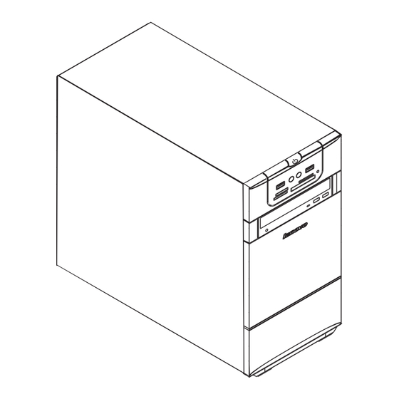
PCI Express adapter card PCI Express adapter connectors Power supply System fan Optical drive Hard disk drive Locating connectors on the front of the computer The following illustration shows the location of connectors on the front of the computer. Power button USB connector Headphone connector Microphone connector... -
Page 8: Locating Connectors On The Rear Of The Computer
Locating connectors on the rear of the computer The following illustration shows the location of connectors on the rear of the computer. The following illustrations show connections located at the rear of some computer models. The locations of connectors on your computer will be similar to, but possibly not identical to these. -
Page 9: Identifying Parts On The System Board
Audio line-out connector Audio line-in connector PCI Express x16 graphics adapter connector (Some models are equipped with this connector. For more information about the graphics adapter, see the description below). WiFi antenna connector (This connector only equipped on the model with WiFi card. - Page 10 Microprocessor and heat sink Microprocessor fan connector Memory connectors(2) Power connector SATA connectors(4) Serial(com1) connector Front panel connector Front USB connectors(2) Front audio connector PCI adapter connector PCI Express x1 adapter connectors(2) PCI Express x16 graphics adapter connector System fan connector 12V power connector Microprocessor and heat sink Microprocessor fan connector...
- Page 11 Memory connectors(2) Memory connectors(2) Thermal sensor header connector Power connector Power fan connector SATA IDE connectors(4) E-SATA connector Front panel connector Front USB connectors(2) Serial (com2) connector Front audio connector PCI adapter connector PCI Express x1 adapter connectors(2) PCI Express x16 graphics adapter connector System fan connector 12V power connector Hardware Replacement Guide...
- Page 12 Microprocessor and heat sink Microprocessor fan connector Memory connector 1 Memory connector 2 Power connector SATA connectors (4) Front panel connector Front USB connectors (2) Serial (com2) connector Front audio connector PCI adapter connector PCI Express x1 adapter connectors (2) Battery PCI Express x16 graphics adapter connector System fan connector...
- Page 13 12v power connector Microprocessor Memory connector Power connector Front panel connector SATA connectors (2) Clear CMOS PCI adapter connector Front USB connectors (2) Front audio connector System fan connector Microprocessor fan connector Microprocessor and heat sink Hardware Replacement Guide 31040542_3000 H_HRG_EN_V3.0.indd10 10 2009.9.7 2:41:32 PM...
- Page 14 Memory connector 1 Memory connector 2 IDE connector Power connector SATA connectors (4) Front panel connector Front USB connectors (2) Battery Clear CMOS Front audio connector PCI adapter connector (2) PCI Express x16 graphics adapter connector PCI Express x1 adapter connectors System fan connector 12v power connector Hardware Replacement Guide...
-
Page 15: Chapter 2 Replacing Hardware
Hardware Maintenance Manual (HMM) for the computer. To obtain copies of the Safety and Warranty Guide or HMM, go to the Support Web site at http://consumersupport.lenovo.com Note: Use only parts provided by Lenovo. - Page 16 chassis. Slide the computer cover to the rear of the chassis to remove. Note: For this procedure, it helps to lay the computer on its side. Hardware Replacement Guide 31040542_3000 H_HRG_EN_V3.0.indd13 13 2009.9.7 2:41:35 PM...
-
Page 17: Removing And Replacing The Front Bezel
Removing and replacing the front bezel To remove and replace the front bezel: Remove the computer cover. Refer to “Removing the computer cover”. Note: For this procedure, it helps to lay the computer on its side. Remove the front bezel by releasing the three plastic tabs inside the chassis and push the bezel outward as shown. -
Page 18: Replacing A Memory Module
Hardware Maintenance Manual (HMM) for the computer. To obtain copies of the Safety and Warranty Guide or HMM, go to the Support Web site at http://consumersupport.lenovo.com To replace a memory module: Remove the computer cover. Refer to “Removing the computer cover”. -
Page 19: Replacing The Hard Disk Drive
Hardware Maintenance Manual (HMM) for the computer. To obtain copies of the Safety and Warranty Guide or HMM, go to the Support Web site at http://consumersupport.lenovo.com To replace the hard disk drive: Remove the computer cover. Refer to “Removing the computer cover”. - Page 20 Disconnect the data and power cables from the hard disk drive. Remove the four screws that secure the hard disk drive from drive bay. Remove the hard disk drive by pulling it straight out of the drive bay. Slide the new hard disk drive into the drive bay. Screw back the four screws on the drive bay.
-
Page 21: Replacing An Optical Drive
Hardware Maintenance Manual (HMM) for the computer. To obtain copies of the Safety and Warranty Guide or HMM, go to the Support Web site at http://consumersupport.lenovo.com To replace an optical drive Remove the computer cover. Refer to “Removing the computer cover”. -
Page 22: Replacing The Keyboard
Hardware Maintenance Manual (HMM) for the computer. To obtain copies of the Safety and Warranty Guide or HMM, go to the Support Web site at http://consumersupport.lenovo.com To replace the keyboard: Before removing any media (diskettes, CDs, or memory cards) from the drives, shut down your operating system, and turn off all attached devices and the computer. -
Page 23: Replacing The Mouse
Hardware Maintenance Manual (HMM) for the computer. To obtain copies of the Safety and Warranty Guide or HMM, go to the Support Web site at http://consumersupport.lenovo.com To replace the mouse: Before removing any media (diskettes, CDs, or memory cards) from the drives, shut down your operating system, and turn off all attached devices and the computer. -
Page 24: Replacing The External Speaker
Replacing the External speaker Before removing any media (diskettes, CDs, or memory cards) from the drives, shut down the computer, and turn off all attached devices. Unplug all power cords from electrical outlets. Locate the Speaker. Refer to “Locating connectors on the rear of the computer” and “Locating connectors on the front of the computer”. - Page 25 Important Correctly route all power supply cables to avoid interference with the drive bay assembly. Keep cables clear of the hinges and sides of the computer chassis. Hardware Replacement Guide 31040542_3000 H_HRG_EN_V3.0.indd22 22 2009.9.7 2:41:46 PM...
- Page 26 Hardware Replacement Guide 31040542_3000 H_HRG_EN_V3.0.indd23 23 2009.9.7 2:41:47 PM...
- Page 27 To update your configuration settings, refer to “Starting the Setup Utility” in the User Guide or in the Hardware Maintenance Manual. Note: In most areas of the world, Lenovo requires the return of the defective CRU. Information about this will come with the CRU or will come a few days after the CRU arrives.
-
Page 28: Appendix
Thanks for using Lenovo products. Carefully read all of the documents shipped with your computer before you install and use the product for the first time. Lenovo will not assume responsibility for damage that results from failure to operate the product according to instructions and requirements described in the manuals included with your computer. - Page 29 Advanced Micro Devices, Inc. in the United States and/ or other jurisdictions. The table above includes the logo and registered trademarks of Lenovo and its partners. Other registered trademarks mentioned in all the manuals included with your computer belong to the specific company respectively.
Need help?
Do you have a question about the H220 and is the answer not in the manual?
Questions and answers