Table of Contents
Advertisement
Quick Links
ESI
Contents - NeON
1. Introduction .......................................................................................................................... 3
2. Basic Features...................................................................................................................... 3
3. Part Description.................................................................................................................... 4
1) Front Panel................................................................................................................... 4
2) Rear Panel ................................................................................................................... 6
4. Installation ............................................................................................................................ 7
1) Unpacking your NeON ................................................................................................. 7
2) Before you connect your NeON Keyboard................................................................... 7
3) Using External Power Supply....................................................................................... 8
4) System Requirements.................................................................................................. 8
5. PC Installation ...................................................................................................................... 9
6. NeON Panel for PC ..............................................................................................................11
1) Pull Down Menus ....................................................................................................... 12
2) Level Faders .............................................................................................................. 13
7. Applications Setup for PC ................................................................................................. 14
1) Cubase SX ................................................................................................................. 14
2) Nuendo....................................................................................................................... 15
3) Wavelab ..................................................................................................................... 15
4) Sonar.......................................................................................................................... 16
5) Tracktion..................................................................................................................... 17
6) ASIO Control Panel .................................................................................................... 17
8. Mac OSX Compatibility and Installation........................................................................... 18
1) Compatibility............................................................................................................... 18
2) Installation .................................................................................................................. 18
3) Audio MIDI Setup ....................................................................................................... 18
9. Applications Setup for Mac ............................................................................................... 19
1) Tracktion..................................................................................................................... 19
2) Cubase SX ................................................................................................................. 19
3) Nuendo....................................................................................................................... 20
10. Operation Guide ............................................................................................................... 21
1) User Interface............................................................................................................. 21
2) Functions:................................................................................................................... 22
Program change ..................................................................................................................................... 22
Advanced Program change .................................................................................................................... 22
MIDI channel........................................................................................................................................... 22
1
Advertisement
Table of Contents

Related Manuals for ESI NeON


Summary of Contents for ESI NeON
-
Page 1: Table Of Contents
Contents – NeON 1. Introduction .......................... 3 2. Basic Features........................3 3. Part Description........................4 1) Front Panel........................4 2) Rear Panel ........................6 4. Installation ..........................7 1) Unpacking your NeON ....................7 2) Before you connect your NeON Keyboard..............7 3) Using External Power Supply.................. - Page 2 Velocity Curve ............................23 Velocity Offset ............................23 Sustain Pedal............................23 Octave +/- ............................... 23 Controller Assign............................. 24 Controller MIDI channel .......................... 24 PAD Assignment ............................. 24 1-8/9-16 Button ............................25 Data Entry Wheel Assignment ........................ 25 Program Store and Recall........................25 Panic...............................
-
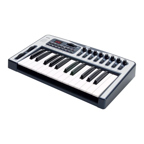
Page 3: Introduction
1. Introduction Thank you for choosing NeON. It combines an USB audio interface with fully functional MIDI control features – all in a portable keyboard. NeON has 25 velocity sensitive keys, 4 control buttons that allow you to control the octave range, select the MIDI channel and assign controller numbers to the wheels. It also features USB connection, one MIDI output, one Sustain Pedal input, one Expression Pedal input, a small case that is not wider than 19ʺ and much more. 2. Basic Features 25 Note full size velocity‐sensitive keyboard. Rubberized pitch bend, modulation and data wheels. 16 Function buttons and 4 Data Buttons. 8 assignable data knobs and 8 assignable encoders for easier data variation. 44.1/48 Khz 24 bit simultaneous 2 channel Audio I/O. Analog I/O: 2 input channels, 2 output channels. USB MIDI In/Out and 1x1 MIDI‐Interface. 1 Headphone Out with Headphone level control. 1 MIC/1 Hi‐Z instrument input jack. Sustain Pedal jack. External DC Power adapter connector. Interface to computer: USB Interface. Windows XP/Mac OS 10.x compatible. -
Page 4: Part Description
3. Part Description 1) Front Panel 1. Pitch bend wheel : Push it up and you bend notes up; pull it down and you bend notes down. 2. Modulation wheel : sends Mod Wheel controller data to control vibrato or tremolo ... - Page 5 3. Numeric Buttons ‐ This button can be used when you enter numerical value directly. And each button has another function when you hold the SHIFT button: No Label Function Descriptions 1 Vel, Curve You can select the Velocity Curve 2 Vel, Offset You can select the Velocity Offset 3 None You can select MIDI Out port (See page 26) 4 Sus, Pedal You can select sustain pedal type 5 MIDI CH Select MIDI Channel 6 Data Entry Assign You can assign Data Wheel to MIDI Controller 7 PAD Assign Assign button to voice 8 PAD MIDI CH Set the PAD MIDI Channel for PAD Assign 9 SAVE Save what you set 0 RECALL Recall setting you saved Please refer to chapter 10 for detailed descriptions 4. Display LCD : This shows you the value of what you operate (parameter, MIDI channel etc.) 5. Oct+/‐ : This buttons can transpose up/down by octaves 6. Ctrl Wheel : You can assign parameter to this wheel for any use, by default 7. Dec/‐ and Inc/+ : You can increase or decrease a value by 1 when editing a parameter. ...
-
Page 6: Rear Panel
2) Rear Panel 10. Power Switch : Press the ʺ|ʺ to turn on NeON or the ʺOʺ to turn it off. 11. DC Power In : Connect your power adapter here. 12. USB connector : Use a USB cable to connect the NeON to your computer. 13. MIDI In/Out port : The MIDI In/Out ports function as a 1x1 MIDI interface. The MIDI Out port can be used in standalone mode if no USB cable is attached, or as a USB MIDI output if a USB cable is connected. The MIDI In port will not function unless a USB cable is connected. 14. Sus.Pedal : By default, this jack is for a sustain pedal, but you can assign any switch type MIDI controller number. 15. Mic In : This jack is the microphone input. 16. Hi‐Z In : This input allows you to directly connect an electric guiar or other high‐impedance signal. 17. Line In : You can connect unbalanced connectors (TS 1/4ʺ) to these inputs 18. Line Out : You can use unbalanced connectors (TS 1/4ʺ) to these inputs, These jacks are connected to external audio devices (Speaker, Mixer, and so on.) 19. H.P Out : Plug your headphones in here. This jack is used for connecting headphone. 20. H.P Level : Adjusts the volume level of the headphone output. ... -
Page 7: Installation
4. Installation 1) Unpacking your NeON Your NeON carton should contain the following; NeON Keyboard Operation Manual USB Cable Installation CD & Tracktion CD If any of the above listed items are missing, please contact the retailer you purchased the product from. You might want to keep the NeON carton and packing materials for easy shipping or transport. 2) Before you connect your NeON Keyboard You are probably eager to plug in your keyboard and get started, but before you begin, please read your computer’s manual on installing USB devices. There is no need to shut down the computer to install USB devices. 1. Find the USB port on your computer. USB ports are usually located by the PS/2 or serial ports in the back. USB port on computer 2. Plug in the appropriate end of a USB cable (called Series A plug) to the USB port of your computer. Notice that USB ports of your computer and NeON’s USB port are different. Series A plug 3. Connect the other end of the USB cable (Series B plug) to the USB port of NeON . Series B plug ... -
Page 8: Using External Power Supply
You can verify correct connection when the LED of NeON lights up. Power is supplied through the USB cable. Series A Plug connectors are used for those devices with a permanently attached external cable, like a Mouse, Keyboard, USB hub etc. Series B Plug connectors are used for devices that require detachable external cables like Printers, Scanners, Modems, and Standalone Hubs. 3) Using External Power Supply We recommend a 9V 500mA DC out adaptor. Just plug in the power supply to the socket labeled DC 9V 500mA and switch the power on. Other adaptors with 9V DC out specification can be used if they are rated at greater than 500mA output. ... -
Page 9: Pc Installation
5. PC Installation 1. Insert the NeON driver CD in the CD‐ROM drive. We recommend you to copy the NeON driver folder to your hard drive. Do not move or delete any of these files, not even after the installation. Run “setup.exe” from this folder. 2. Click “Next” and follow the instructions on the screen. ... - Page 10 5. Checking your system. Go to: Control Panel > Sounds and Audio Devices > Audio. Please check if your audio devices are installed properly. ...
-
Page 11: Neon Panel For Pc
6. NeON Panel for PC The panel allows you to easily configure the settings of NeON to your needs. After successfully installing the NeON drivers you will see the ESI panel icon in the system tray of the task bar. Icon Clicking on this icon will launch the NeON panel. ... -
Page 12: Pull Down Menus
The default setting for input is “LINE IN”. You need to click another button to select MIC/Hi‐Z input. This will close the NeON panel window but it will not shut down the panel. You can always relaunch the panel by clicking on the icon. 1) Pull Down Menus 1. File – Factory Default Return all NeON configuration settings to factory default. 2. File ‐ Always On Top Set the NeON panel to appear always over other windows. If this is not selected, the active windows of other applications will be shown over the NeON panel. 3. File ‐ Exit Shut down the NeON panel. 4. About Check current soft and hardware information. ... -
Page 13: Level Faders
2) Level Faders You can move both faders at the same time, click the space between faders and move. 1. Input Adjust input monitoring level of NeON. You can select input type between MIC/HI‐Z and LINE IN with button. Active Input shows like this. Set the level using the mouse, mouse wheel, or cursor keys. The number on the bottom indicates the relative level in dB. 2. Output Adjust output level of NeON. There are two kinds of outputs – WDM OUT and H.P OUT(Headphone Out). WDM OUT is the same that Windows wave out. In case of H.P OUT, the number on the bottom indicates ... -
Page 14: Applications Setup For Pc
7. Applications Setup for PC The NeON supports applications using WDM, MME and ASIO. This section provides quick setup guide for some common recording applications. For more detailed information, please consult the application’s user manual. 1) Cubase SX After launching Cubase, go to Device Setup > VST Multitrack. Select ‘ASIO 2.0 – ESI NeON’ as ASIO driver. Set MIDI input and output as ‘ESI – NeON MIDI1(or 2)’ as shown below. ... -
Page 15: Nuendo
2) Nuendo After launching Nuendo, go to Device Setup > VST Multitrack. Select ‘ASIO 2.0 – ESI NeON’ as ASIO driver. 3) Wavelab After launching WaveLab, go to Option > Preferences > Audio Card. Choose ‘ASIO 2.0 ‐ ESI NeON’ as Playback and Record device as shown below. ... -
Page 16: Sonar
4) Sonar After launching Sonar, go to Audio Options and select ‘ESI – NeON’. Sonar ver. 2.2 and higher can use ASIO drivers. Set audio input and output as shown below. Set MIDI input and output as shown below. ... -
Page 17: Tracktion
Note: NeON driver CD includes Ultimate Audio Tools (UAT) bundle software. They are located in ‘ESI’ folder of the driver CD. Only applications listed in the NeON box work with NeON. Other applications are for other ESI products sharing the same universal ESI driver CD. -
Page 18: Mac Osx Compatibility And Installation
8. Mac OSX Compatibility and Installation 1) Compatibility NeON only works with OS 10.2 or later versions of Mac OSX. If you have earlier versions of Mac OS, please upgrade before using the NeON. 2) Installation Please connect the NeON to the USB port on your Mac. No driver installation is needed. NeON uses the Mac OS X native USB audio driver. 3) Audio MIDI Setup Configure NeON as default audio input and output device as shown below. Audio MIDI Setup can be found in Applications\Utilities folder. ... -
Page 19: Applications Setup For Mac
9. Applications Setup for Mac 1) Tracktion NeON comes bundled with the full version of Tracktion ‐ professional recording and MIDI production software by Mackie. After launching Tracktion, select ‘Settings’ then ‘audio devices’ tab. Choose NeON as playback and record device as shown below. 2) Cubase SX After launching Cubase, go to Device Setup > VST Multitrack. Select ‘NeON(1)’ as ASIO driver. ... -
Page 20: Nuendo
3) Nuendo After launching Nuendo, go to Device Setup > VST Multitrack. Select ‘NeON(1)’ as ASIO driver. ... -
Page 21: Operation Guide
10. Operation Guide 1) User Interface The general format for changing a parameter on NeON is (SHIFT) + FUNCTION ‐> VALUE ‐> ENTER Many functions are accessed using the SHIFT key in combination with another button. The SHIFT key should be held down while the desired function is selected. Modifying assignable controllers is similar but requires an additional step. When a value needs to be entered, the number can be typed in using the buttons 0‐9 on the front panel. Additionally, the INC/DEC buttons can be used to increment or decrement the current displayed value by 1. When the buttons 0‐9 are not used to enter numeric data, the default functions are as programmable MIDI triggers. These can be used as drum pads or to trigger samples, or simply play any MIDI note. Note number and MIDI channel are independently programmable for each pad. Pad velocity is fixed at ... -
Page 22: Functions
2) Functions: Program change Press the PROG CHANGE button. The LED in the button will light. Type in the program number 0‐127 Press ENTER. The LED will turn off Advanced Program change This allows an extended program change function for devices that require it or for accessing programs greater than 127 via bank selection. This is a 4‐step process Press SHIFT + PROG CHANGE buttons. The LED in the button will light. Type in BANK MSB. Press ENTER. Next, type in BANK LSB. Press ENTER. Finally, type the Program number. Press ENTER. The LED will turn off, completing the operation MIDI channel Press SHIFT + MIDI CHAN. Display will show current MIDI Channel. Type in the new MIDI channel 1‐16. Press ENTER. Note : MIDI channel numbers entered greater than 16 are invalid. ... -
Page 23: Velocity Curve
Velocity Curve Neon has 4 internal velocity curves. Default at power‐up is always 1. To change: Press SHIFT + Vel. Curve. Type in 1‐4. Press ENTER Velocity curve numbers greater than 4 are invalid and will be ignored if entered. Velocity Offset A programmable offset can be added to the velocity generated by the keyboard. This value can be in the range ‐64 to +64. Default at power‐up is no offset. To change: Press SHIFT + Vel. Offset. For positive values, first press the INC/+ button to indicate a positive value. The LED next to the button will light up. Next, type in the value 0‐64. For negative values, first press the DEC/‐ button to indicate a negative value (LED will light up), then type in the number 0‐64. Press ENTER to complete the operation. Sustain Pedal The Sustain Pedal input can be programmed to accept normally‐open or normally‐closed types of sustain ... -
Page 24: Controller Assign
Controller Assign This function allows the assignment of any controller number 0‐127 to any of the controller knobs, data entry wheel, or faders. Pitch and Modulation are always fixed functions. To initiate an assignment, do the following: Press the Ctrl Assign button. The LED will light. Next, move the controller you wish to modify. The number of that controller will be displayed on the LED display. Type in the MIDI controller number you wish to assign to the controller. Press ENTER to complete the process. Controller MIDI channel This function allows the assignment of a MIDI channel to any of the controller knobs, data entry wheel, or faders. To initiate an assignment, do the following: Press the SHIFT + Ctrl Assign button. The LED will light. Next, move the controller you wish to modify. The number of that controller will be displayed on the LED display. Type in the MIDI channel number you wish to assign to the controller. Press ENTER to complete the process. PAD Assignment Assignment of a PAD is a 2‐step process. This includes assignment of the MIDI note number and also a ... -
Page 25: 1-8/9-16 Button
1-8/9-16 Button NeON supports 16 control pots and 16 faders, even though only 8 of each are located on the front panel. To switch banks, press the 1‐8/9‐16 button. When in 1‐8 mode, the LED in the button will be off, when in 9‐16 mode it will be on. Data Entry Wheel Assignment The Data Wheel can be assigned either using the Ctrl Assign procedure as described above or the following: Press the SHIFT + Data Entry Assign button. The LED will light. Next, move the Data Wheel. The number of the controller will be displayed on the LED display. Type in the MIDI controller number you wish to assign to the controller. Press ENTER to complete the process. Assigning a MIDI channel to the Data Wheel is the same as described above. Program Store and Recall NeON can save up to 16 configurations in internal memory. All controllers, MIDI channel, and other settings are saved in non‐volatile memory. Patch 0 is default and is loaded at power‐up. This cannot be ... -
Page 26: Audio And Midi Interfaces
Audio and MIDI Interfaces The audio functions of NeON are accessed through control panels on the host PC. There are no front‐ panel features to control audio or MIDI interface functions. Audio Outputs NeON provides stereo line outputs. These output levels are controlled from the host PC. The headphone outputs are independently controlled by the volume output control on the rear panel of NeON. Audio Inputs NeON has 4 inputs. 2 are line inputs. One is a Mic input calibrated for low‐level, low‐impedance microphone inputs. The last input is a Hi‐Z (high impedance) input suitable for guitars and other Hi‐Z ... -
Page 27: Standard Controller Numbers
3) Standard Controller numbers STANDARD CONTROLLER NUMBERS No. Controller 35 Controller 35 69 Hold 2 103 Controller 103 00 Bank Select 36 Foot Control LSB 70 Sound Variation 104 Controller 104 01 Modulation 37 Porta Time LSB 71 Resonance 105 Controller 105 02 Breath Control 38 Data Entry LSB 72 Release Time 106 Controller 106 03 Controller 3 39 Channel Volume LSB 73 Attack Time 107 Controller 107 04 Foot Control 40 Balance LSB 74 Cutoff Frequency 108 Controller 108 05 Porta Time 41 Controller 41 75 Controller 75 109 Controller 109 06 Data Entry 42 Pan LSB 76 Controller 76 110 Controller 110 07 Channel Volume 43 Expression LSB 77 Controller 77 ... -
Page 28: Specifications
11. Specifications <Physical Spec> 25 professional sized keys with semi‐weighted spring action Rubberized Pitch, Mod and Data wheels <Analog Audio> 1. Analog Inputs 1) Connector Type : 1/4ʺ female TS‐type, unbalanced(ch 1/2) 2) Attenuation & Gain Control : ‐34dB to +12dB(1.5dB step size) 2. Analog Outputs 1) Connector Type : 1/4ʺ female TS‐type, unbalanced(ch 1/2) 3. Microphone Preamplifier 1) Maximum input level: 1Vrms 2) Maximum input gain : +34dB 4. Headphone Amplifier 1) Output power: 30mW @ 32 ohms/50mW @ 16 ohms <MIDI> 1) 1 USB MIDI Port (16 channel) 2) 1 In / 1 Out MIDI Interface (16 channel) ... -
Page 29: Appendix - Factory Preset List
Appendix – Factory Preset List Preset 0 (Default) – GM Knob Channel Controller Definition Cutoff Reverb Chorus Attack Release Resonance Expression Encoder Channel Controller Definition Volume Volume Volume Volume Volume Volume Volume Volume Preset 1 – Mixer 1-8 ... -
Page 30: Preset 2 - Ni Pro 53 Edit
Preset 2 – NI Pro 53 Edit Knob Channel Controller Definition Cutoff Resonance Volume VCF ENV VCA Attack VCA Decay VCA Sustain VCA Release Encoder Channel Controller Definition Osc A Freq Osc B Freq Osc B Fine Glissando VCF Attack VCF Decay VCF Sustain... -
Page 31: Preset 6 - Reason Subtractor Edit
Preset 6 – Reason Subtractor Edit Knob Channel Controller Definition Filt. 1 Freq Filt. 1 Res Filter ENV Volume VCA Attack VCA Decay VCA Sustain VCA Release Encoder Channel Controller Definition LFO Rate LFO Amount Filt 2 Freq Filt. -
Page 32: Preset 10 - Trilogy & Atmosphere
Preset 10 – Trilogy & Atmosphere Knob Channel Controller Definition Volume Filt. 1 Freq Filt. 1 Res Filter ENV VCA Attack VCA Decay VCA Sustain VCA Release Encoder Channel Controller Definition Layer Sel LFO Rate Mst Filt Freq Mst Filt Res VCF Attack VCF Decay...
Need help?
Do you have a question about the NeON and is the answer not in the manual?
Questions and answers