Table of Contents
Advertisement
Quick Links
Advertisement
Table of Contents

Subscribe to Our Youtube Channel
Related Manuals for Gigabyte GA-Q67M-D2H-B3


Summary of Contents for Gigabyte GA-Q67M-D2H-B3
- Page 1 GA-Q67M-D2H-B3 User's Manual Rev. 1002 12ME-Q67M2HB-1002R...
-
Page 3: Identifying Motherboard Revision
The trademarks mentioned in this manual are legally registered to their respective owners. Disclaimer Information in this manual is protected by copyright laws and is the property of GIGABYTE. Changes to the specifications and features in this manual may be made by GIGABYTE with- out prior notice. -
Page 4: Table Of Contents
Table of Contents GA-Q67M-D2H-B3 Motherboard Layout ................5 GA-Q67M-D2H-B3 Motherboard Block Diagram ............6 Chapter 1 Hardware Installation ..................7 Installation Precautions ................... 7 Product Specifications ..................8 Installing the CPU and CPU Cooler............... 10 Installing the Memory ..................11 Installing an Expansion Card ................11 Back Panel Connectors ................. -
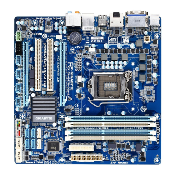
Page 5: Ga-Q67M-D2H-B3 Motherboard Layout
GA-Q67M-D2H-B3 Motherboard Layout KB_USB ATX_12V VGA_DVI LEVEL SHIFTER LGA1155 DP_HDMI_SPDIF LEVEL SHIFTER R_USB SYS_FAN USB_LAN AUDIO CPU_FAN GA-Q67M-D2H-B3 PCIEX16 PCI1 BIOS IT8728 Intel 82579 CLR_CMOS PCI2 Intel ® SATA3_0 SATA3_1 PCIEX4 SATA2_3 SATA2_2 SPDIF_O SATA2_5 SATA2_4 CODEC DEBUG_PORT F_USB1 F_USB4 COMA COMB F_USB3... -
Page 6: Ga-Q67M-D2H-B3 Motherboard Block Diagram
GA-Q67M-D2H-B3 Motherboard Block Diagram 1 PCI Express x16 CPU CLK+/- (100 MHz) LGA1155 DDR3 1333/1066/800 MHz Dual Channel Memory PCIe CLK (100 MHz) PCI Express Bus DisplayPort 1 PCI Express x4 HDMI RJ45 DVI-D PCIe CLK D-Sub Intel (100 MHz) 82579 BIOS Intel... -
Page 7: Chapter 1 Hardware Installation
Chapter 1 Hardware Installation Installation Precautions The motherboard contains numerous delicate electronic circuits and components which can become damaged as a result of electrostatic discharge (ESD). Prior to installation, carefully read the user's manual and follow these procedures: Prior to installation, do not remove or break motherboard S/N (Serial Number) sticker or •... -
Page 8: 1-2 Product Specifications
Dual channel memory architecture Š Support for DDR3 1333/1066/800 MHz memory modules Š Support for non-ECC memory modules Š (Go to GIGABYTE's website for the latest supported memory speeds and memory modules.) Onboard Integrated in the Chipset: Š Graphics 1 x D-Sub port 1 x DVI-D port, supporting a maximum resolution of 1920x1200 * The DVI-D port does not support D-Sub connection by adapter. - Page 9 Internal 1 x 24-pin ATX main power connector Š Connectors 1 x 4-pin ATX 12V power connector Š 2 x SATA 6Gb/s connectors Š 4 x SATA 3Gb/s connectors Š 1 x CPU fan header Š 1 x system fan header Š...
-
Page 10: Installing The Cpu And Cpu Cooler
Form Factor Micro ATX Form Factor; 24.4cm x 24.4cm Š * GIGABYTE reserves the right to make any changes to the product specifications and product-related information without prior notice. Installing the CPU and CPU Cooler Read the following guidelines before you begin to install the CPU: Make sure that the motherboard supports the CPU. -
Page 11: Installing The Memory
Make sure that the motherboard supports the memory. It is recommended that memory of the • same capacity, brand, speed, and chips be used. (Go to GIGABYTE's website for the latest supported memory speeds and memory modules.) Always turn off the computer and unplug the power cord from the power outlet before installing •... -
Page 12: Back Panel Connectors
Back Panel Connectors USB 2.0/1.1 Port The USB port supports the USB 2.0/1.1 specification. Use this port for USB devices such as a USB key- board/mouse, USB printer, USB flash drive and etc. PS/2 Keyboard/Mouse Port Use this port to connect a PS/2 mouse or keyboard. D-Sub Port The D-Sub port supports a 15-pin D-Sub connector. - Page 13 DisplayPort DisplayPort is one of the new generation interface technologies that delivers high quality digital imaging and audio, supporting bi-directional audio transmition. DisplayPort can support both DPCP and HDCP content protection mechanisms. Connect the audio/video device that supports DisplayPort to this port. The DisplayPort Technology can support a maximum resolution of 2560x1600p but the actual resolu- tions supported depend on the monitor being used.
-
Page 14: Internal Connectors
Internal Connectors ATX_12V F_AUDIO SPDIF_O CPU_FAN F_USB1/F_USB2/F_USB3/F_USB4 SYS_FAN COMA/COMB SATA3_0/1 DEBUG_PORT SATA2_2/3/4/5 CLR_CMOS F_PANEL Read the following guidelines before connecting external devices: First make sure your devices are compliant with the connectors you wish to connect. • Before installing the devices, be sure to turn off the devices and your computer. Unplug the •... - Page 15 1/2) ATX_12V/ATX (2x2 12V Power Connector and 2x12 Main Power Connector) With the use of the power connector, the power supply can supply enough stable power to all the com- ponents on the motherboard. Before connecting the power connector, first make sure the power supply is turned off and all devices are properly installed.
- Page 16 3/4) CPU_FAN/SYS_FAN (Fan Headers) The motherboard has a 4-pin CPU fan header (CPU_FAN), a 4-pin system fan header (SYS_FAN). Most fan headers possess a foolproof insertion design. When connecting a fan cable, be sure to connect it in the correct orientation (the black connector wire is the ground wire). The motherboard supports CPU fan speed control, which requires the use of a CPU fan with fan speed control design.
- Page 17 6) SATA3_0/1 (SATA 6Gb/s Connectors, Controlled by Intel Q67 Chipset) The SATA connectors conform to SATA 6Gb/s standard and are compatible with SATA 3Gb/s and SATA 1.5Gb/s standard. Each SATA connector supports a single SATA device. The SATA3_0 and SATA3_1 connectors support RAID 0 and RAID 1.
-
Page 18: Front Panel Header
8) F_PANEL (Front Panel Header) Connect the power switch, reset switch, speaker, and system status indicator on the chassis to this header according to the pin assignments below. Note the positive and negative pins before connecting the cables. Message/Power/ Power Speaker Sleep LED Switch... - Page 19 9) F_AUDIO (Front Panel Audio Header) The front panel audio header supports Intel High Definition audio (HD) and AC'97 audio. You may connect your chassis front panel audio module to this header. Make sure the wire assignments of the module con- nector match the pin assignments of the motherboard header.
- Page 20 11) F_USB1/2/3/4 (USB 2.0/1.1 Headers) The headers conform to USB 2.0/1.1 specification. Each USB header can provide two USB ports via an optional USB bracket. For purchasing the optional USB bracket, please contact the local dealer. Pin No. Definition Power (5V) Power (5V) USB DX- USB DY-...
- Page 21 13) LPT (Parallel Port Header) The LPT header can provide one parallel port via an optional LPT port cable. For purchasing the optional LPT port cable, please contact the local dealer. Pin No. Definition Pin No. Definition STB- AFD- ERR- INIT- ACK- SLIN-...
-
Page 22: Clear Cmos Jumper
15) CLR_CMOS (Clearing CMOS Jumper) Use this jumper to clear the CMOS values (e.g. date information and BIOS configurations) and reset the CMOS values to factory defaults. To clear the CMOS values, place a jumper cap on the two pins to temporarily short the two pins or use a metal object like a screwdriver to touch the two pins for a few seconds. -
Page 23: Chapter 2 Bios Setup
Chapter 2 BIOS Setup To access the BIOS Setup program, press the <Delete> or <F2> key during the POST when the power is turned on. Because BIOS flashing is potentially risky, if you do not encounter problems using the current •... -
Page 24: Advanced
System Date/Time Sets the system date/time. Use the <Tab> key to switch between data/time elements. Advanced Aptio Setup Utility - Copyright (C) 2010 American Megatrends, Inc. Main Advanced Chipset Boot Security Save & Exit Legacy OpRom Support Launch PXE OpRom [Disabled] Launch Storage OpRom [Enabled]... - Page 25 Wake system with Dynamic Time Enables or disables system wake on alarm event. When enabled, the system will wake on the current time+Increase minute(s). Trusted Computing TPM SUPPORT Enables or disables TPM support. O.S. will not show TPM. Reset of platform is required. CPU Configuration This screen provides information on CPU frequencies/parameters.
-
Page 26: Chipset
AMT Configuration Allows you to set the AMT Parameters. Serial Port Console Redirection Enables or Disables Serial Port Console Redirection. Chipset Aptio Setup Utility - Copyright (C) 2010 American Megatrends, Inc. Main Advanced Chipset Boot Security Save & Exit } North Bridge } South Bridge } ME Subsystem : Select Screen... -
Page 27: Security
Bootup Numlock State Selects the keyboard NumLock state. Full Screen LOGO Show Allows you to determine whether to display the AMI Logo at system startup. Disabled displays normal POST message. Fast Boot Enables or disables the quick boot function to speed up the system boot-up process to shorten the wait- ing time for entering the operating system and to deliver greater efficiency for daily use. -
Page 28: Save & Exit
Save & Exit Aptio Setup Utility - Copyright (C) 2010 American Megatrends, Inc. Main Advanced Chipset Boot Security Save & Exit Save Changes and Exit Discard Changes and Exit Save Changes and Reset Discard Changes and Reset Save Options Save Changes : Select Screen Discard Changes : Select Item... -
Page 29: Chapter 3 Drivers Installation
Chapter 3 Drivers Installation • Before installing the drivers, first install the operating system. • After installing the operating system, insert the motherboard driver disk into your optical drive. The driver Autorun screen is automatically displayed which looks like that shown in the screen shot below. - Page 30 Configuring the Onboard SATA Controller A. Installing SATA hard drive(s) in your computer Attach one end of the SATA signal cable to the rear of the SATA hard drive and the other end to available SATA port on the motherboard. Then connect the power connector from your power supply to the hard drive. (Note) B. Configuring SATA controller mode in BIOS Setup Make sure to configure the SATA controller mode correctly in system BIOS Setup.
- Page 31 Making a SATA RAID Driver Diskette (for Windows XP) Before installing Windows XP, connect a USB floppy disk drive to your computer first because you need to install the SATA RAID/AHCI driver from a floppy disk that contains the driver during the OS installation. To copy the RAID driver for Windows XP 32-bit operating system, copy all files in the \BootDrv\iRST\32Bit folder to your floppy disk.
- Page 32 WEB address (English): http://www.gigabyte.com WEB address (Chinese): http://www.gigabyte.tw You may go to the GIGABYTE website, select your language in the language list on the top right corner of the website. • GIGABYTE Global Service System To submit a technical or non-technical (Sales/Market- ing) question, please link to: http://ggts.gigabyte.com.tw...
Need help?
Do you have a question about the GA-Q67M-D2H-B3 and is the answer not in the manual?
Questions and answers