Table of Contents
Advertisement
Quick Links
Download this manual
See also:
Owner's Manual
Advertisement
Table of Contents

Related Manuals for Echo LAYLA24


Summary of Contents for Echo LAYLA24
- Page 1 LapTop LapTop LapTop LapTop LAYLA LAYLA LapTop LapTop LapTop LapTop MONA MONA ™ ™ GINA ™ Owner’s Manual Version 3.0 for Windows Designed and Manufactured in the U.S. by Echo Corporation...
-
Page 2: Important Safety Instructions
Important Safety Instructions 1. Read Instructions - Be sure to read all of the safety and operating instructions before operating this product. 2. Retain Instructions - The safety instructions and owner's manual should be retained for future reference. 3. Heed Warnings - All warnings on your Echo product and in the Owner's Manual should be followed. -
Page 3: Limited Warranty
Sending in your registration card – or registering online at http://www.echoaudio.com/register.html - allows us to register key information so that we may handle problems faster and inform you of advance information on upgrades and other news. Thanks in advance for filling out your registration card and sending it to us. We hope you enjoy your Echo product. -
Page 4: Table Of Contents
INTRODUCTION....................6 ..........6 HOULD ECEIVED IN THE ..................7 YSTEM EQUIREMENTS INSTALLATION ....................8 ....................8 YSTEM OUNDS . WDM - D ........8 ECIDING HICH RIVER TO NSTALL PCI C ........9 NSTALLING THE ARD FOR ESKTOP OMPUTERS ......12 NSTALLING THE DAPTER FOR APTOP OMPUTERS CONNECTING TO LAYLA24’S RACK-MOUNT AUDIO INTERFACE ..14 CONNECTING TO MONA’S RACK-MOUNT AUDIO INTERFACE..18 CONNECTING TO GINA24’S AUDIO INTERFACE ........23... - Page 5 ....................48 ..................49 REFERENCES I/O - S S/PDIF O ........49 IGITAL ELECTING THE UTPUT ORMAT I/O - D ................50 IGITAL ITHER NPUT ....................50 AMPLE VXD CONSOLE - MIA ..................51 ....................52 NPUT ONTROLS ...................52 ONITOR ONTROLS ................54 IRTUAL UTPUT ONTROLS .....................55 UTPUT ONTROLS ...........55 DJUSTING...
-
Page 6: Introduction
Introduction – all products Introduction Thank you for choosing Echo Digital Audio. We think you’ll find your Echo product to be an extremely flexible, high-performance tool for your computer- based hard disk recording system. What You Should Have Received in the Box When you opened the box, you should have found the following: A PCI card wrapped in an anti-static cover OR a CardBus Adapter... -
Page 7: System Requirements
Introduction – all products System Requirements In order to use Layla24, Mona, Gina24 or Mia you’ll need the following: A desktop computer one of the following: A genuine Intel Pentium processor and genuine Intel chipset OR An AMD Athlon or Duron processor with one of the following chipsets: Via KX-133 Via KT-133 Via KT-133a... -
Page 8: Installation
Installation – all products Installation Complete installation consists of disabling Windows system sounds, deciding which Echo driver you are going to use, installing the Windows drivers into your system, installing the PCI or CardBus card, connecting the audio interface to the card (Layla24, Mona, and Gina24) and, if necessary, installing a multitrack audio recording/editing application. -
Page 9: Installing The Pci Card For Desktop Computers
Installation – all products Installing the PCI Card for Desktop Computers Once you have verified that there are no problems with your system, it is time to install the Echo PCI card into your computer. 1. Install the drivers. You should do this before inserting the PCI card. Insert the Echo Install CD-ROM into your machine. - Page 10 Installation – all products 7. Now use the screw that you removed earlier, from the protective back plate, to attach the metal bracket on the card to the computer’s rear panel. 8. OPTIONAL: (If you have Mia, skip this step.) Esync cables come with Darla24 and Gina24, and can be used to daisy chain several 24-bit Echo cards together.
- Page 11 Installation – all products Note: This version of the WDM driver has not been digitally signed by Microsoft; for Windows 2000 and XP, you will need to confirm that you want to install an unsigned driver. Installation – all products...
-
Page 12: Installing The Cardbus Adapter For Laptop Computers
Installation – all products Installing the CardBus Adapter for Laptop Computers Once you have verified that there are no problems with your system, it is time to install Layla24 LapTop or Mona LapTop into your laptop computer. 1. Install the drivers. You should do this before inserting the CardBus Adapter. Insert the Echo Install CD-ROM into your machine. - Page 13 Installation – all products While it is possible to “hot-dock” the card by inserting it with the laptop powered up, it is recommended the card only be inserted or removed with the power off. If you have to remove the card with your computer turned on, the card must first be disabled.
-
Page 14: Connecting To Layla24'S Rack-Mount Audio Interface
Audio connections – Layla24 Connecting to Layla24’s Rack-mount Audio Interface The back panel of Layla24’s rack-mount audio interface contains a wide variety of connections that allow great flexibility in the operation of Layla24. For optimal performance with Layla24, it is critical to use the appropriate cabling and connectors. - Page 15 Audio connections – Layla24 The Computer Connector Next to the analog inputs and outputs is a connector labeled COMPUTER. This connector is known as a DB-9, and is similar to the serial port on a PC. It is the point at which the audio interface connects to the Layla24 PCI card inside your computer.
- Page 16 Audio connections – Layla24 S/PDIF Next to the ADAT connectors is a pair of connectors labeled S/PDIF, IN and OUT. These S/PDIF connectors are used to transmit digital data among digital audio devices via an electrical signal. S/PDIF data can use the full 24-bit sample width used internally on Layla24.
- Page 17 Audio connections – Layla24 MIDI The last set of connections to the Layla24 interface is for MIDI. The MIDI ports can be used for receiving MIDI time code (MTC), or sending MIDI signals from your digital audio/MIDI sequencing software to external sound modules, etc. MIDI cabling is highly standardized and widely available.
-
Page 18: Connecting To Mona's Rack-Mount Audio Interface
Audio connections – Mona Connecting to Mona’s Rack-mount Audio Interface The back panel of Mona’s rack-mount audio interface contains a wide variety of connections that allow great flexibility in the operation of Mona. To achieve the optimal performance with Mona, it is critical that the appropriate cabling and connectors are used. - Page 19 Audio connections – Mona Mona’s Line Input (1/4” TRS, Impedance: 10K, Trim: 0 – 40dB) When a ¼” connector is plugged into Mona’s universal input jack, the microphone preamp is disconnected and a line input amplifier is inserted in its place. If the GUITAR switch is out, the line input provides a balanced connection (for TRS plugs) and the trim knob has a range of 0 to 40dB.
- Page 20 Audio connections – Mona For optimal audio quality, you should adjust the input trim (knob) so that your loudest recorded signal lights up some of the yellow bars, but not the red. If the signal level ever exceeds 0dB the signal will be “clipped” and you will hear a “pop”...
- Page 21 Audio connections – Mona ADAT/S/PDIF optical I/O Next to the COMPUTER connector is a pair of connectors labeled OPTICAL, IN and OUT. These connectors are used to transmit digital data among digital audio devices via an optical signal. You can use this port for ADAT (8 channels) or for optical S/PDIF (stereo) I/O. Note: Mona is only capable of transmitting or receiving one type of digital signal at a time.
- Page 22 Audio connections – Mona Word Clock Next to the S/PDIF ports are the Word Clock connectors. These connectors allow you to synchronize one Mona to another Mona, Layla or Layla24 or to other digital audio devices. The word clock I/O uses a BNC connector. As with the S/PDIF I/O, a shielded 75- ohm (RG-59) coaxial video cable should be used.
-
Page 23: Connecting To Gina24'S Audio Interface
Audio connections – Gina24 Connecting to Gina24’s Audio Interface The back panel of Gina24’s audio interface contains a wide variety of connections that allow great flexibility in the operation of Gina24. To achieve the optimal performance with Gina24, it is critical that the appropriate cabling and connectors are used. - Page 24 Audio connections – Gina24 ADAT/S/PDIF optical I/O Next to the COMPUTER connector is a pair of connectors labeled OPTICAL, IN and OUT. These connectors are used to transmit digital data among digital audio devices via an optical signal. You can use this port for ADAT (8 channels) or for optical S/PDIF (stereo) I/O. Note: Gina24 is only capable of transmitting or receiving one type of digital signal at a time.
-
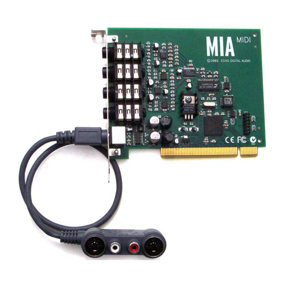
Page 25: Connecting To Mia
Audio connections – Mia Connecting to Mia Analog Inputs and Outputs Mia has two analog outputs (OUT1 and OUT2) and two analog inputs (IN1 and IN2) on the back. The input and output connections can accept balanced or unbalanced jacks via ¼” connectors. -
Page 26: Using Audio Software - Gina24, Layla24, And Mona
Audio Software – Gina24, Layla24, and Mona Using Audio Software – Gina24, Layla24, and Mona To audio software, the Echo hardware appears as a group of stereo wave devices. You can view the list of these devices either from within your audio software or from the Windows control panel. - Page 27 Audio Software – Gina24, Layla24, and Mona The WDM drivers work a little differently, depending on the current digital mode. Gina24, Layla24, and Mona have a digital mode switch that lets you set how the hardware transmits and receives digital audio signals. The digital mode switch can be set to S/PDIF RCA, S/PDIF optical, or ADAT optical.
-
Page 28: Using Audio Software - Mia
Using Audio Software – Mia Using Audio Software – Mia To audio software, the Mia hardware appears as a group of stereo wave devices. You can view the list of these devices either from within your audio software or from the Windows control panel. The items you see in the list will depend on what driver you installed. -
Page 29: Mia's Virtual Outputs
Virtual outputs – Mia Mia’s Virtual Outputs Most cards with a pair of analog inputs and outputs will appear to software as having just that, a single pair of inputs and outputs. When one application appropriates the card for its use, all other software is “locked-out” from using the card at the same time. -
Page 30: Console3 (Wdm)
WDM console – all products Console3 (WDM) This section of the manual applies only if you installed the WDM drivers. A “virtual control surface” application called Console3 is included with the WDM driver. The Console allows you to control the audio I/O and clocking functions of your Echo product, and it brings these controls to a single easy-to-use location. -
Page 31: Bus Select
WDM console – all products Screenshot of Layla24 Console3 main window - other Echo hardware will work similarly. Bus select The bus select panel is the area outlined in green. Eight different output busses are shown here: four analog busses in the top row and four digital busses on the bottom row. -
Page 32: Analog Inputs
WDM console – all products The two buttons labeled “+4” are the nominal level select buttons. Since they both read “+4,” this indicates these outputs are sending a +4 dBu (professional level) signal. To send a –10 dBV (consumer level) signal, click the button. This feature allows you to connect either professional or consumer gear to each output. -
Page 33: Digital Inputs
WDM console – all products pan and mute controls, this does not affect your record level. Also, clicking on the readout below the fader will allow you to numerically enter a fader setting. The analog inputs also have gang buttons, and their operation is the same as the gang button for the master outputs. -
Page 34: Adjusting Playback Volume
WDM console – all products Mia gets around this by combining the use of “virtual” outputs with its “multi- client” drivers. Mia appears to software as if it has eight separate outputs. These are mixed together with Mia’s on-board DSP to produce the actual or “physical” outputs that connect to external equipment without any CPU intervention. - Page 35 WDM console – all products Layla24, Mona, Gina24 and Mia are designed to work alongside other audio equipment. If you are planning on using your card with other audio equipment, please note the following: The Windows drivers included in this package support multiple Echo cards within the same system.
- Page 36 WDM console – all products cables. Unlike wire cables, fiber optic cables do not add noise or interference. Layla24/Mona/Gina24 can send out (or “master”) ADAT clock as well slave to it. If you want the interface to slave to an ADAT clock, just set the input clock to the ADAT setting.
- Page 37 WDM console – all products Now let’s take a look at some sample configurations and how you might set them up from a synchronization standpoint. Let’s start simple. Suppose that Layla24 is the only audio device used in your system. Since you have no other devices to synchronize with, simply select Internal for Layla24’s input clock.
-
Page 38: Console Settings
WDM console – all products Console Settings Clicking the Settings button above the playback strips shows a dialog box for altering console settings. The Settings dialog gives you four different tabs to choose from: “Driver,” “Digital I/O,” “GSIF,” and “About.” Driver Here you can do two things: lock the sample rate and tell the driver whether or not to synchronize wave devices. -
Page 39: Synchronize Wave Devices
WDM console – all products Synchronize wave devices This is mainly for developers who are using tools like Visual Basic or Delphi and want the inputs and outputs to be totally independent. Unless you have a good reason to turn it off, you should leave this switch on. Also, if you are running multiple applications on one card and you can’t get it to work, try un-checking this box. -
Page 40: Gsif
WDM console – all products GSIF This window allows you to set the latency of GigaStudio in terms of samples. Select the value here that provides the best tradeoff between performance and reliability. About This displays the console version and driver version numbers. We feel that this is the single most exciting feature on the new console. -
Page 41: Vxd Console - Gina24, Layla24, And Mona
VxD console – Gina24, Layla24, and Mona VxD Console – Gina24, Layla24, and Mona This section of the manual only applies if you installed the VxD drivers and are using Gina24, Layla24, or Mona. A “virtual control surface” application called the Console is included with the VxD driver. -
Page 42: Console Controls
VxD console – Gina24, Layla24, and Mona further grouped into a box that contains selection buttons, faders, and other controls and displays as determined by the function. Console Controls Let’s take a look at the control surface. The input control area is located in the upper left portion of the console surface. - Page 43 VxD console – Gina24, Layla24, and Mona in the selected output pair. Both pan controls and faders can be reset to default by pressing the Ctrl button and left clicking on the control. Instead of level meters, each monitor control has a series of numbered buttons. These buttons allow you to select which output channel pair controls are displayed, so you can adjust them.
-
Page 44: Output Controls
VxD console – Gina24, Layla24, and Mona Note: You cannot monitor the S/PDIF inputs through the ADAT outputs and vice versa (Layla24, Mona, Gina24). This is because you can only use one digital mode (S/PDIF or ADAT) at any given time. For more information, please see the section “Digital Mode Switch”... -
Page 45: Setting Clock Sources And Destinations
VxD console – Gina24, Layla24, and Mona Setting Clock Sources and Destinations At the very bottom of the Console there are buttons that allow you to select the synchronization clocks. The console program will detect which input clocking options are available, and automatically disable those that are unavailable. Depending on what external devices you have connected, you may have as many as four out of five options available (Layla24/Mona). - Page 46 VxD console – Gina24, Layla24, and Mona Let’s take a brief look at the various synchronization types. Word Clock – This is a synchronization signal that connects to the BNC connector labeled Word Clock on Layla24/Mona’s back panel. This synchronization clock runs at the selected sample rate. Think of it as a kind of electronic metronome, which clicks back and forth at the digital sample rate.
- Page 47 VxD console – Gina24, Layla24, and Mona Layla24 and Mona only have the Esync output connectors, and Mia has no Esync connectors. Layla24/Mona/Gina24 is always outputting Esync clock. Now, let’s take a look at some example configurations and how you might set them up from a synchronization standpoint.
-
Page 48: The File Menu
VxD console – Gina24, Layla24, and Mona The File Menu At the top left of the Console window you will find the File menu. By selecting the File menu, several configuration options become available to you. The first menu option is “Preferences.” The Preferences option brings up the Console “Preferences Page”... -
Page 49: The Preferences Page
VxD console – Gina24, Layla24, and Mona The Preferences Page The Preferences Page is accessible through the Console File menu. Digital I/O - Selecting the S/PDIF Output Format Your Echo hardware can transmit digital information in either of two formats, “professional”... -
Page 50: Digital I/O - Dither Input
VxD console – Gina24, Layla24, and Mona Digital I/O - Dither Input In the top right is a checkbox labeled Dither Input. This checkbox allows you to enable or disable dithering on the digital inputs. It is off by default. Most of the time you will want to leave this setting disabled. -
Page 51: Vxd Console - Mia
VxD console- Mia VxD Console - Mia This section only applies if you installed the VxD drivers and are using Mia. A “virtual control surface” application called the Console is included with the VxD driver. Every time you start Windows you will see it flicker across the screen as it loads. -
Page 52: Input Controls
VxD console- Mia into a box that contains selection buttons, faders, and other controls and displays as determined by the function. Input Controls Let’s take a look at the control surface. The input control area is located in the upper left portion of the console surface. - Page 53 VxD console- Mia monitoring through the digital outputs that are hidden from view. Clicking on the large “Output Controls” button labeled “Digital” at the bottom of the console will display the monitor controls for monitoring through the digital outputs. These controls are labeled “...
-
Page 54: Virtual Output Controls
VxD console- Mia Virtual Output Controls The middle of the console is dedicated to the controls for virtual output channels one through eight. The output controls look like the monitor controls (Gang, Mute, Solo, & faders), except that there are also meters that show the levels for each of the virtual outputs. -
Page 55: Output Controls
VxD console- Mia Output Controls The right hand side of the console is dedicated to the controls for the “physical” analog and digital outputs. An output meter pair is included for the two S/PDIF output channels, but these levels are not adjustable. -
Page 56: Synchronizing Multiple Devices
VxD console- Mia There are also buttons for selecting controls that affect either the analog outputs or the digital outputs. When “Analog” is selected, the monitors and virtual output controls for the analog outputs are displayed within the Console. When “Digital” is selected, the controls for the digital outputs are shown. - Page 57 VxD console- Mia Let’s start simple. Suppose that Mia is the only audio device used in your system. Since you have no other devices to synchronize with, simply select “Internal” for Mia’s input clock. Mia will then use its own clock to control its operation. Now a little more complicated set-up: You have two Mias connected.
-
Page 58: The File Menu
VxD console- Mia The File Menu At the top left of the Console window you will find the File menu. By selecting the File menu, several configuration options become available to you. The first menu option is “Preferences.” The Preferences option brings up the Console “Preferences Page”... -
Page 59: Digital I/O - Selecting The S/Pdif Output Format
VxD console- Mia Digital I/O - Selecting the S/PDIF Output Format Mia can transmit digital information in either of two formats, “professional” or “consumer.” The primary difference between the two is in the implementation of the SCMS copy protection bit, which, in the Consumer format, prevents the user from making digital copies of a digital copy. -
Page 60: Sample Rate Lock
VxD console- Mia Sample Rate Lock These controls allow you to enable or disable the Sample Rate Lock feature, as well as set the sample rate you want to lock to. While the sample rate is locked, all sample rate change requests from applications will be ignored and the hardware will remain at that sample rate no matter what. -
Page 61: Additional Configuration Settings (Vxd Drivers)
Additional VxD console settings –all products Additional Configuration Settings (VxD Drivers) In addition to those settings that can be made using the Console program, there are a number of other configuration options available only to users of Windows 98/Me. These are found in the Windows Control Panel. To access these controls, begin by pressing the Windows Start button. -
Page 62: Show Console On Taskbar
Additional VxD console settings –all products Show console on taskbar The first selection in the General section of the Settings screen allows you to determine whether the Console program will occupy a space on the Windows taskbar (for example, Mia’s blue “M” in the bottom right-hand corner of the Windows desktop). -
Page 63: Multi-Client Audio
Additional VxD console settings –all products Multi-client audio Multi-client audio lets you use different inputs and outputs on your Echo audio system with different audio programs at the same time. Otherwise, you would have to use a different audio device with each audio application. - Page 64 Additional VxD console settings –all products The first checkbox is called “Enable DirectSound for analog outputs.” This allows you to enable or disable the DirectSound driver for the analog outputs only. The second checkbox is called “Enable DirectSound for digital outputs.” This allows you to enable or disable the DirectSound driver for the digital outputs only.
-
Page 65: Cubasis Vst
Cubasis VST – all products Cubasis VST Installing Cubasis Included with your Echo 24 system is a special version of Steinberg’s Cubasis VST, a complete audio and MIDI recording studio. Here you can record and arrange your musical ideas, create a mix, add effects and finally produce a finished file ready for burning to CD-R. - Page 66 Cubasis VST – all products 2. Pull down the ASIO Device pop-up menu, and select your ASIO driver; if you installed the VxD drivers, select “ASIO Echo Layla24/Mona/Gina24/Mia,” or if you installed the WDM drivers, select “ASIO Echo WDM.” In simple terms, the ASIO Device is the mechanism that allows audio data to be transferred between Cubasis VST and your Echo product.
-
Page 67: Contacting Echo Customer Service
Customer Service – all products Contacting Echo Customer Service If you experience any trouble with your Echo hardware please go to the support area of our website at www.echoaudio.com, and check out the tutorials & troubleshooting FAQ’s we have there. If you can’t find a solution to your problem there, please fill out the provided technical support email form. -
Page 68: Appendix A: General Troubleshooting Guide
Appendix A: General Troubleshooting Guide Note: For the latest information about software compatibility, please visit our website, echoaudio.com. Problem: After installing your Echo product, one or more of your peripheral devices no longer functions properly. Solution: During the installation of your Echo product under Win98/Me it is possible that an interrupt conflict was created. - Page 69 Unfortunately there is no way for the transmitting device to automatically detect which format the receiving device is able to accept. If you have a DAT deck that is not able to read the S/PDIF output from your Echo card, chances are it is transmitting in the mode that the deck is not equipped to handle.
- Page 70 Problem: On Windows startup you hear a high pitched squealing sound or your S/PDIF signal has gone crazy. Solution: Reset the sample rate. Windows always sets the sample rate to 11kHz at startup. Because S/PDIF doesn’t support this rate, you will have problems syncing until you reset your Echo hardware’s sample rate to one within spec (like 44.1 or 48kHZ).
-
Page 71: Appendix B: Resolving Irq Conflicts - Windows 98/Me
Appendix B: Resolving IRQ Conflicts - Windows 98/Me We estimate that 95% of Echo installations will go without a hitch that Plug- and-Play will properly assign resources to your card without any conflicts. The other 5% of you may experience interrupt problems (mostly caused by non-Plug- and-Play ISA cards or PCI cards that don’t like to share). - Page 72 be assigned or “steered” to one of the 11 available PC interrupts by either the BIOS or Windows 98/Me. As far as the user is concerned, PCI interrupts use the same numbers and are assigned the same way as Plug-and-Play ISA interrupts. Note, however, that a PCI card can share an interrupt with another PCI card but not with an ISA card.
- Page 73 Resolving Interrupt Conflicts Although there is no way to automatically detect legacy interrupts, Windows 98/Me and some BIOS’s allow you to reserve specific interrupts for legacy use. Once an interrupt is reserved it will not be assigned by Plug-and-Play to another card.
- Page 74 If the offending card is a PCI card, you may want to skip to the section on “Reconfiguring an IRQ within Windows 98/Me - PCI” a few pages down.
- Page 75 Reserving an IRQ within the BIOS – Legacy ISA Other than removing the offending legacy card, the next most effective method is to reserve the IRQ for legacy use within your BIOS. To do this you will need to enter the BIOS configuration screen when your computer first starts up. This is usually done by pressing the Delete key or F1 key right after the memory test during the boot-up routine.
- Page 76 Reconfiguring an IRQ within Windows 98/Me - PCI Now that you have identified the offending card and the IRQ in contention, you will want to try to reconfigure its IRQ setting. To do this, you must open the Device Manager. Select Start – Settings – Control Panel – System, and click the Device Manager tab.
-
Page 77: Appendix C: Multi-Client Audio Faq
Appendix C: Multi-client audio FAQ Q: What is “Multi-client audio”? Multi-client audio is a feature that lets you use different inputs and outputs on your Echo card with different applications at the same time. This way, you can use several different audio applications with just one Echo card. Otherwise, you would have to use a different audio device for each audio application. - Page 78 out of an unused output and drop the sample rate of the whole system to 22, ruining your take. If you really want system sounds, go buy a $30 cheapo sound card and play them through that. Set the preferred device in the Multimedia control panel to the cheapo sound card and check “Use preferred devices only.”...
-
Page 79: Appendix D: Wdm-Windows Driver Model Faq
Appendix D: WDM-Windows Driver Model FAQ Q: What is a WDM driver and why should I care? WDM stands for “Windows Driver Model.” Microsoft realized they were asking hardware manufacturers to write a lot of different drivers: support for Windows NT, Windows 95, support for the wave API, support for DirectSound, etc. - Page 80 The new driver is a WDM driver. This means it was natively developed for Windows 2000 (that is, it’s not a legacy driver running on a newer OS). However, WDM drivers work differently (again, this is simplified): Audio application ⇓ Microsoft’s WDMAUD wave driver ⇓...
- Page 81 Q: Why can't I record or play at 24-bit resolution? The short answer is that WDM audio drivers only support 24-bit audio if the application is using Microsoft's new “extensible” wave format. Many existing apps do not support this format. This only affects programs that use the wave/MME or DirectSound APIs.
-
Page 82: Appendix E: An Introduction To Digital Recording
Appendix E: An Introduction to Digital Recording Converting Sound into Numbers In a digital recording system, sound is represented as a series of numbers, with each number representing the voltage, or amplitude, of a sound wave at a particular moment in time. The numbers are generated by an analog-to-digital converter, or ADC, which converts the signal from an analog audio source (such as a guitar or a microphone) connected to its input into numbers. - Page 83 Figure B. The more bits there are available, the more accurate the representation of the signal and the greater the dynamic range. Your Echo card’s analog inputs use 24-bit ADCs, which means that the incoming signal can be represented by any of over 16 million possible values. The output DACs are also 24-bit;...
- Page 84 Decibels Audio signal levels are generally expressed in units called “decibels” which are abbreviated as “dB”. This is a “logarithmic” scale where each doubling of signal level is represented by an increase of 6dB. Therefore a signal of 6dB is twice as big as a 0dB signal and a signal of 12dB is four times as big as a 0dB signal.
- Page 85 The above nominal levels represent typical or average levels that are often exceeded when recording loud signals such as drum beats. The difference between the nominal level and the loudest signal that can be recorded without clipping is called “headroom”. Your Echo card provides approximately 14dB of headroom allowing an 18dBu signal to be recorded.
- Page 86 Dynamic Range Dynamic range represents the difference between the maximum signal that can be recorded and the “noise floor”, or level of noise with no signal present. A system with a high dynamic range will be quieter than one with a lower dynamic range. Dynamic range is a very important specification, and your echo card uses converters that have very high dynamic range.
-
Page 87: Appendix F: Specifications
Appendix F: Specifications Gina24 - Audio Performance Analog Inputs (x2 balanced TRS): Frequency Response: 10Hz – 22kHz, 0.25dB ± Dynamic Range: 108dB A-weighted THD+n: <0.001%, 20Hz–22kHz A-weighted Nominal Input Level: +4 dBu Maximum Input Level: +18dBu Input Impedence: 10K Analog Outputs (x8 balanced TRS): Frequency Response: 10Hz –... - Page 88 Layla24 - Audio Performance Analog Inputs (x8 balanced TRS): Frequency Response: 10Hz – 22kHz, 0.25dB ± Dynamic Range: 110dB A-weighted THD+n: <0.001%, 20Hz–22kHz A-weighted Nominal Input Level: +4 dBu Maximum Input Level: +22dBu Input Impedence: 10K Analog Outputs (x8 balanced TRS): Frequency Response: 10Hz –...
- Page 89 Mona -Audio Performance Analog Inputs (x4): Frequency Response: 10Hz – 22kHz, 0.25dB ± Dynamic Range: 110dB A-weighted THD+n: <0.001%, 20Hz–22kHz Nominal Input Level: +4 dBu Maximum Input Level: +22dBu Microphone Input Level (balanced XLR): EIN: -129dBV Input Impedance: 1.5K Gain Adjustment: 20 – 60dB Line Input Level (balanced TRS): Input Impedance: 10K Gain Adjustment: 0 –...
- Page 90 Mona - Hardware Host Interface: PCI bus mastering card Four high quality mic preamps with phantom power (+48v) Four universal analog inputs with precision 24-bit 128x oversampling analog- to-digital converters Six analog outputs (both XLR & RCA) with high performance 24-bit 128x oversampling digital-to-analog converters S/PDIF digital I/O with up to 24-bit resolution ADAT optical digital I/O...
- Page 91 Mia - Audio Performance Analog Inputs (x2 balanced TRS): Frequency Response: 10Hz – 22kHz, 0.5dB ± Dynamic Range: 106dB A-weighted THD+n: <0.001%, 20Hz–22kHz Nominal Input Level: +4 dBu Maximum Input Level: +18dBu Input Impedence: 10K Analog Outputs (x2 balanced TRS): Frequency Response: 10Hz –...
- Page 92 input trims ........20 install multiple Layla24s ....68 +4dBu/–10dBV switch.... 42, 44 interface box, installing ..14, 23 interface cable ........6 interrupt conflicts....68, 72, 73 ADAT ......15, 24, 35, 46 adjusting record and playback levels ........34, 44, 55 Layla24 installation ......8 analog resolution ......
- Page 93 S/PDIF output setting..49, 59, 69 S/PDIF recording ......68 technical support......67 S/PDIF resolution......83 .......68 troubleshooting guide sample rate........82 TRS ......... 25, 85 sample rate lock....... 50, 60 SAW compatibility mode....62 SCMS copy-protection..49, 59, 68 unbalanced ........85 selecting a slot ........
Need help?
Do you have a question about the LAYLA24 and is the answer not in the manual?
Questions and answers