Table of Contents
Advertisement
Advertisement
Table of Contents

Related Manuals for AllTrade 647376


Summary of Contents for AllTrade 647376
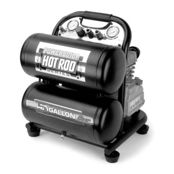
- Page 1 TWIN TANK AIR COMPRESSOR 5 Gallon / 3 Peak HP 226892 If you encounter any problems or difficulties, Do not return your compressor to the store! 1-800-423-3598 • 1-310-522-9008 (California Only) • www.alltradetools.com Please contact our toll-free customer service department at: Model #647376...
-
Page 2: Table Of Contents
It is the owner and/or operator’s responsibility to study all WARNINGS, operating, and maintenance instructions contained on the product label and instruction manual prior to operation of this unit. The owner/operator shall retain product instructions for future reference. The owner and/or operator is responsible for maintenance, maintaining all decals or warning labels and while in use, maintaining the unit in good working order. -
Page 3: Specifications
SPECIFICATIONS Two Pole Induction Motor Power Air Delivery Maximum Pressure Duty Cycle 3.0 Peak HP / 1.3 Running HP 5 Gallon Twin Stack Air Tank Oil Lubricated Direct Drive Pump Cast Iron Cylinder Thermal Overload Protection for Safety High Flow Regulator for Precision Air Flow Control Tank and Outlet Pressure Gauges Dual Quick Connect Coupler Duty Cycle:... -
Page 4: Introduction
INTRODUCTION This oil lubricated air compressor is designed for Household Use Only and is not intended for commercial applications. It is well suited for do-it- yourselfers with a variety of automotive and home uses. This instruction manual is intended for your benefit. Please read and follow the safety, installation, maintenance and troubleshooting steps described within to ensure your safety and satisfaction. -
Page 5: General Safety Warnings
READ ALL SAFETY WARNINGS BEFORE USING AIR COMPRESSOR. GENERAL SAFETY WARNINGS: • Keep work area clean. Messy areas and cluttered workbenches invite personal injury and/or property damage. • Keep children and visitors away. All children should be kept away from the work area. DO NOT let children handle the compressor or extension cord. - Page 6 DRAIN LIQUID FROM AIR TANK DAILY • Use the drain valve located on the bottom of the lower air tank to drain. Failure to properly drain liquid from the tank will cause rust from moisture buildup, which weakens the tank and could lead to a violent tank explosion. Periodically inspect the tanks for unsafe conditions such as corrosion, cracked welds, and leaks.
-
Page 7: Risk Of Falling
RISK OF FALLING Portable air compressors can fall from a table, workbench, or roof causing damage to the compressor and could result in serious injury or death to the operator. Always operate air compressor in a stable and secure position to prevent accidental movement of the unit. Never operate air compressor on a roof or other elevated position. -
Page 8: Compressor Features
IMPROPER INSTALLATION OF THE GROUNDING PLUG CAN RESULT IN A RISK OF ELECTRIC SHOCK. IF REPAIR OR REPLACEMENT OF THE CORD IS NECESSARY, DO NOT CONNECT THE GROUNDING WIRE TO EITHER FLAT BLADE TERMINAL. THE WIRE WITH GREEN INSULATION WITH OR WITHOUT YELLOW STRIPES IS THE GROUNDING WIRE. THIS PRODUCT IS FOR USE ON A NOMINAL 120-VOLT CIRCUIT AND HAS A THREE-PRONG GROUNDING PLUG THAT LOOKS LIKE THE PLUG ILLUSTRATED IN FIGURE 1. - Page 9 COMPRESSOR FEATURES...
- Page 10 OIL LUBRICATION: Oil lubricated direct drive pump with cast-iron cylinder for durability. OIL FILL SIGHT GLASS: Located on the face of the crankcase, the oil fill sight glass provides a convenient way to check the oil fill level within the pump. The oil level must be checked prior to each use to ensure proper fill level. DO NOT OPERATE THE COMPRESSOR WITHOUT LUBRICANT, OR WITH LOW LUBRICATION LEVEL.
-
Page 11: Assembly Instructions
MANUAL THERMAL OVERLOAD SWITCH: The electric motor has a manual thermal overload protector. If the motor overheats for any reason, the thermal overload protector will shut off the motor. Turn pressure switch to the “off” position and wait for unit to cool before pushing the reset button and restarting the compressor. -
Page 12: Step 2 - Inspection Check
STEP 2 – INSPECTION CHECK Assembly Check: In order to complete the assembly of your new air compressor, a careful inspection should be made to ensure that all of the parts are properly aligned and securely fastened. 1. Inspect air filter to ensure that it is installed and secure. 2. -
Page 13: Maintenance
DISCONNECT AIR COMPRESSOR FROM POWER SOURCE AND BLEED OFF ALL AIR PRESSURE SHUTDOWN AND STORAGE: NOTE: NEVER stop the air compressor by unplugging it from the power outlet as this may result in damage to the compressor. 1. Turn the switch to the OFF position 2. -
Page 14: Checking Safety Relief Valve
Fig. 4 CHECKING SAFETY RELIEF VALVE: SAFETY RELIEF VALVE MUST BE REPLACED IF IT CANNOT BE ACTUATED OR IT LEAKS AIR AFTER THE RING IS RELEASED. 1. The air compressor must be turned OFF. 2. Disconnect compressor from the power source. 3. -
Page 15: Troubleshooting Guide
Problem Encountered Possible Cause The compressor does not Power cord not plugged in. start or restart: Motor/Pressure switch in OFF position Motor thermal overload switch has tripped. Fuse blown or circuit breaker has tripped. Wrong gauge wire or length of extension cord. - Page 16 Problem Encountered Possible Cause Air continues to leak at Defective motor/pressure switch. motor/pressure switch release Check valve stuck in open position. valve while motor is running: Air leaks from safety relief Possible defective safety relief valve. valve: Excessive tank pressure. Air leaks at pump: Blown gaskets.
-
Page 17: Parts List
PART NO. DESCRIPTION 647376-1 Bolt 647376-2 Spring Washer 647376-3 Cylinder Head 647376-4 Exhaust Elbow 647376-5 Gasket, Cylinder Head 647376-6 Valve Plate 647376-7 Bolt 647376-8 Spring Washer 647376-9 Plate Washer 647376-10 Valve Plate 647376-11 Reed Valve, Intake 647376-12 647376-13 Reed Valve, Exhaust... -
Page 18: Parts Diagram
PARTS DIAGRAM... -
Page 19: Limited Warranty
Parts returned, freight prepaid and insured, to Alltrade’s facility (see above address) will be inspected and, at Alltrade’s option, repaired and/or replaced free of charge if found to be defective and subject to warranty. Alltrade retains the sole discretion to determine whether any item or part is nonconforming and, if so, whether the item and/or part will be repaired and/or replaced. - Page 20 Alltrade will not be liable for the following: labor charges, loss or damage resulting from improper operation, maintenance or repairs made by other persons; pre-delivery services such as assembly, oil or lubricants, and adjustment; maintenance services that are normally required to maintain the air compressor.
- Page 21 1431 Via Plata Long Beach, CA 90810-1462 Made in: China ©2006 REV.1, Alltrade Tools LLC www.alltradetools.com HOT ROD Magazine is a trademark of PRIMEDIA Specialty Group, Inc. and is used with permission. © 2006 PRIMEDIA Specialty Group, Inc. All rights reserved.
Need help?
Do you have a question about the 647376 and is the answer not in the manual?
Questions and answers
je désire acheter le régulateur de pression qui donne plus ou moins de pression le bouton que l'on tourne soit vers la droite ou la gauche il est situé sur le panneau avant