Table of Contents

Related Manuals for Acer TravelMate 4050


Summary of Contents for Acer TravelMate 4050
- Page 1 TravelMate 4050 Service Guide Service guide files and updates are available on the ACER/CSD web; for more information, please refer to http://csd.acer.com.tw PRINTED IN TAIWAN Service CD P/N:WE DO NOT PRODUCE CD FOR THIS MODEL...
-
Page 2: Revision History
Revision History Please refer to the table below for the updates made on TravelMate 4050 service guide. Date Chapter Updates... - Page 3 Copyright Copyright © 2004 by Acer Incorporated. All rights reserved. No part of this publication may be reproduced, transmitted, transcribed, stored in a retrieval system, or translated into any language or computer language, in any form or by any means, electronic, mechanical, magnetic, optical, chemical, manual or otherwise, without the prior written permission of Acer Incorporated.
- Page 4 Conventions The following conventions are used in this manual: SCREEN Denotes actual messages that appear MESSAGES on screen. NOTE Gives bits and pieces of additional information related to the current topic. WARNING Alerts you to any damage that might result from doing or not doing specific actions.
- Page 5 DIFFERENT part number code to those given in the FRU list of this printed Service Guide. You MUST use the list provided by your regional Acer office to order FRU parts for repair and service of customer machines.
-
Page 6: Table Of Contents
Table of Contents Chapter 1 System Specifications Features ............1 System Block Diagram . - Page 7 Table of Contents Chapter 6 FRU (Field Replaceable Unit) List Exploded Diagram ..........67 TravelMate 4050 Parts .
-
Page 8: System Specifications
Li-Ion main battery pack ® Wireless solution with integrated Intel PRO/Wireless 2200BG network connection 802.11b/g Inprocomm 802.11 b/g, dual band Wi-Fi CERTIFIED solution; Acer SignalUp wireless technology support Display 14.1” or 15.0” Thin-Film Transistor (TFT) displaying at 1024x768 XGA and 1400x1050 SXGA resolution ®... - Page 9 ® Integrated Intel PRO/Wireless 2200BG network connection 802.11b/g dual band Wi-Fi CERTIFIED solution, Inprocomm 802.11b/g Acer SignalUp wireless technology support ® Wireless PAN integrated Bluetooth Battery 4/8 cells Li-ion 18650 size (2150mAh) main battery pack with 31/63W Capacity Supports 2.5/5 hrs operation time (battery mark 2002, in XGA resolution) Approximated charging time 3~8 hrs (System On) or 2.5hr (System Off)
- Page 10 Parallel port External display (VGA) port Microphone Jack Headphones/Speaker/Line-Out port Infrared (FIR) port PC Card Slot (one Type II) DC-In jack for AC adaptor Chapter 1...
-
Page 11: System Block Diagram
System Block Diagram Mobile Dothan/Banias Thermal Sensor Clock Generator uFCBGA/uFCPGA CPU ADM1032 ICS950810CG 478 pin page 4,5 page 4 page 13 HA#(3..31) HD#(0..63) System Bus Fan Control 400MHz page 31 Memory BUS(DDR) LVDS & CRT DDR-SO-DIMM X2 Montara 855GME Connector page 19 2.5V 266MHz/333MHz BANK 0, 1, 2, 3... -
Page 12: Board Layout
Mainboard Placement Top View Item Description Item Description CRT CONN JP17 ODD CONN Parallel Port JP18 SPK CONN IEEE1394 CONN JP19 TP/B CONN TV-OUT CONN JP20 MIC JACK RJ11/RJ45 CONN JP22 K/B CONN USB CONN X 2 JP23 PHONE JACK CPU FAN CONN JP16 HDD CONN... - Page 13 Bottom View Item Description Item Description JP25 SO-DIMM Socket SIO Controller JP26 SO-DIMM Socket IEEE1394 Controller CarBus Controller Chapter 1...
-
Page 14: Outlook View
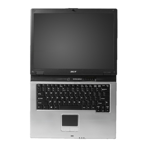
Outlook View A general introduction of ports allow you to connect peripheral devices, as you would with a desktop PC. Front Open View Item Description Display screen Also called Liquid-Crystal Display (LCD), displays computer output. Power button Turns on the computer. Launch keys Two special keys for frequently used programs. -
Page 15: Front View
Front View Item Description Optical drive Internal optical drive; accepts CDs or DVDs depending on the optical drive type. Optical drive eject Ejects the optical drive tray from the drive. button Emergency eject hole Ejects the optical drive tray when the computer is turned off. -
Page 16: Left View
Left View Item Description One USB 2.0 port Connects to Universal Serial Bus devices (e.g., USB mouse, USB camera). Infrared port Interfaces with infrared devices (e.g., infrared printer, IR- aware computer). PC Card slot Accepts one Type II 16-bit PC Card or 32-bit CardBus PC Card. -
Page 17: Right View
Right View Item Description Stereo speaker Outputs sound Houses the computer's hard disk DC-in jack Connects the AC adapter Ventilation Slot Enables the computer to stay cool, even afterprolonged use. Chapter 1... -
Page 18: Rear View
Rear View Item Description Security keylock Connects to a Kensington-compatible computer security lock Parallel port Connects to a parallel device (e.g., parallel printer) External display port Connects to a display device (e.g., external monitor, LCD projector) and displays up to16.7 million colors and up to 1600x1200 at 85 Hz and 2048x1536 at 75 Hz resolution. - Page 19 Bottom View Item Description Optical drive Internal optical drive; accepts CDs or DVDs depending on the optical drive type Memory compartment Houses the computer's main memory Hard disk bay Houses the computer's hard disk (secured by a screw) Battery compartment Unlatches the battery to remove the battery compartment release latch Battery bay...
-
Page 20: Indicators
Indicators The computer has six easy-to-read status icons below the display screen. The status LCD displays icons that show the status of the computer and its components. Icon Function Description Icon Function Description Lights when Hard Disk Drive is activated. Icon Function Description... -
Page 21: Lock Keys
Lock Keys The keyboard has four lock keys which you can toggle on and off. Lock Key Description Caps Lock When Caps Lock is on, all alphabetic characters typed are in uppercase. Pad lock When Pad Lock is on, the embedded keypad is (Fn-F10) enabled. -
Page 22: Embedded Numeric Keypad
Embedded Numeric Keypad The embedded numeric keypad functions like a desktop numeric keypad. It is indicated by small characters located on the right hand side of the keycaps. Desired Access Num Lock On Num Lock Off Number keys on embedded Type numbers in a normal keypad manner. -
Page 23: Windows Keys
Windows Keys The keyboard has two keys that perform Windows-specific functions. Description Windows logo key Start button. Combinations with this key perform special functions. Below are a few examples: + Tab (Activates next taskbar button) + E (Explores My Computer) + F (Finds Document) + M (Minimizes All) + M (Undoes Minimize All) -
Page 24: Hot Keys
Hot Keys The computer uses hotkey or key combinations to access most of the computer’s controls like sreen brightness and volume output. To activate hot keys, press and hold the Fn key before pressing the other key in the hot key combination. Hot Key Icon Function... -
Page 25: The Euro Symbol
The Euro Symbol If your keyboard layout is set to United States-International or United Kingdom or if you have a keyboard with a European layout, you can type the Euro symbol on your keyboard. NOTE: For US keyboard users: The keyboard layout is set when you first set up Windows. For the Euro symbol to work, the keyboard layout has to be set to United States-International. -
Page 26: Launch Keys
Located at the top of keyboard are three buttons. The left-most button is the power button. To the right of the power button are the two launch keys. They are designated as the programmable buttons (P1 and P2). Launch Key Default application Launch key Default application Acer eManager application (User-programmable) User-programmable Chapter 1... -
Page 27: Touchpad
Touchpad The built-in touchpad is a pointing device that senses movement on its surface. This means the cursor responds as you move your finger on the surface of the touchpad. The central location on the palmrest provides optimum comfort and support. Touchpad Basics The following items teach you how to use the touchpad: Move your finger across the touchpad to move the cursor. -
Page 28: Hardware Specifications And Configurations
Hardware Specifications and Configurations Processor Item Specification CPU type ® ® Intel Pentium M Processor at 1.4~2.1 GHz ® ® Intel Celeron M Processor at 1.2~1.5 GHz CPU package µ FCBGA package CPU core voltage ® ® Intel Pentium M Processor supports automatic selection of power supply voltage CPU I/O voltage 1.05V... -
Page 29: Memory Combinations
Memory Combinations Slot 1 Slot 2 Total Memory 128MB 128MB 256MB 256MB 512MB 512MB 1024MB 1024MB 128MB 128MB 128MB 128MB 256MB 128MB 256MB 384MB 128MB 512MB 640MB 128MB 1024MB 1152MB 256MB 256MB 256MB 128MB 384MB 256MB 256MB 512MB 256MB 512MB 768MB 256MB 1024MB... - Page 30 Hard Disc Drive Interface Item Specification Functionality Model Name Toshiba Hitachi Seagate MK3025GAS HTS424030M9AT00 2.75”W. 37”H ST94019A Capacity (MB) 30000 30000 40000 Bytes per sector Data heads Data Disks Spindle speed (RPM) 4200 RPM 4200 RPM 4200 RPM Performance Specifications Buffer size 2048KB Interface...
- Page 31 Combo Drive Interface Item Specification Loading mechanism Load: Manual Release: (a) Electrical Release (Release Button) (b) Release by ATAPI command (c) Emergency Release Power Requirement Input Voltage +5 V +/- 5 % (Operating) +/- 8 % (Start up) Input Voltage +5 V +/- 0.25V DVD-ROM Interface Item...
-
Page 32: Audio Interface
DVD Dual Interface Item Specification Vendor & model name QSI SDW-082S Lite-On SOSW-852S Performance Specification With CD Diskette With DVD Diskette Transfer rate (KB/sec) (Mode1) 3.3X-8X CAV 4463-10820KByte/s 4X-5.7X PCAV 600-855KByte/s 10.3X-24X CAV 1552-3600KByte/s (Mode2) 4X-5.7X PACV 684.4-975.3KBytes/s 10.3X-24X CAV 1769-4104KByte/s Data Buffer Capacity 192 KBytes Interface... -
Page 33: Video Interface
Video Interface Item Specification Video vendor UMA (855GME) Support bbp 15/16/24/32 bbp True Color on LCD& dual view Chip voltage Core/1.35V Supports ZV (Zoomed Video) port Parallel Port Item Specification Parallel port controller LPC47N217 Number of parallel port Location Rear side Connector type 25-pin D-type connector, in female type Parallel port function control... -
Page 34: System Board Major Chips
System Board Major Chips Item Controller System core logic 855GHE/ICH4-M Super I/O controller LPC47N217 Audio controller ALC250 Video controller Hard disk drive controller ICH4-M Keyboard controller KB910 Keyboard Item Specification Keyboard controller KB910 Keyboard vendor & model name Standard keyboard w/o launch button embeded Total number of keypads 85/US, 86/UK keys with 101/102 key emulation Windows logo key... - Page 35 LCD : 14.0” /15.0” Item Specification 15.0” Vendor & model name Samsung B150XG02 V2 HW:2 LTN150XB-L03-C00 Mechanical Specifications LCD display area 15” 15” (diagonal, inch) Display technology Resolution 1024 x 768 1024 x 768 Supports colors 262K 262K Dot Pitch 0.297mm 0.297mm Optical Specification...
-
Page 36: Power Management
AC Adapter Item Specification Input Current (100Vac, 240Vac / larger than or equal to 1.5A 3.5A loag) Output Characteristics Output Rated Voltage Output Current 0A to 3.5A Output Voltage Setting 19.5V to 21V Output Voltage Ripple and larger than or equal to 300mVp-p Noise(90Vac/70W load;... -
Page 37: Mechanical Specification
Mechanical Specification Item Specification I/O Ports One type II CardBus slots, one RJ-11 modem jack, one RJ-45 network jack, one DC-in jack for AC adapter, one ECP/EPP-compliant parallel port, one external monitor port, one headphone/speaker/line-out jack (3.5mm mini jack), one microphone/line-in jack (3.5mm mini jack), three Universal Serial Bus (USB) ports, one IEEE 1394 port, one S-video port Material... -
Page 38: System Utilities
Chapter 2 System Utilities BIOS Setup Utility The BIOS Setup Utility is a hardware configuration program built into your computer’s BIOS (Basic Input/ Output System). Your computer is already properly configured and optimized, and you do not need to run this utility. However, if you encounter configuration problems, you may need to run Setup. -
Page 39: Bios Setup Utility
Manufacture Name A manufacture name string will be stored in the secured data area. It is defined §R £ as “Acer” stored 16 bytes in total length with checksum. System BIOS Version This field reports the BIOS version of system. - Page 40 Parameter Description Memory Base Memory This field reports the memory size of system base memory. The size is fixed to 640KB. Extended Memory This field reports the memory size of the extended memory in the system. Extended Memory size = Total memory size - 127 MB VGA Memory VGA Memory size = 16MB Insyde Software SCU...
-
Page 41: Advanced
Advanced The Advanced screen contains parameters involving your hardware devices. It also provides advanced settings of the system. Insyde Software SCU May 20, 2003 5:40:09 Main Advanced Security Boot Exit -----------------------------FIR Ports------ -------------------- Infrared Port (FIR) -----FIR I/O settings--- -Mode Setting for IRDA- ( ) Disabled ( ) Normal (16550) ( ) COM1,3F8,IRQ4... -
Page 42: Lpt Port
LPT Port Configure the system’s parallel port using options: Disabled and Enabled. Insyde Software SCU May 20, 2003 5:40:09 Main Advanced Security Boot Exit ----------------- Parallel Port (LPT) ------------------------------ -----Port Address------- ---Port Definition----- Infrared Port (FIR) ) None ) Standard AT (Centronics) ( £»... - Page 43 Legacy USB Support Disabled: Disable support for Legacy Universal Serial Bus. Enabled: Enable support for Legacy Universal Serial Bus. Insyde Software SCU May 20, 2003 5:40:09 AM Main Advanced Security Boot Exit Infrared Port (FIR) Parallel Port (LPT) £ Legacy USB support Legacy USB keyboard, Floppy Drive, USB Mouse Support <Space>...
-
Page 44: Security
§ § fi Security § The Security screen contains parameters that help safeguard and protect your computer from unauthorized § use. fi § Insyde Software SCU May 20, 2003 5:40:09 § Main Advanced Security Boot Exit § Set Supervisor Password §... -
Page 45: Boot
Boot This menu allows the user to decide the order of boot devices to load the operating system. Bootable devices includes the diskette drive in module bay, the onboard hard disk drive and the CD-ROM in module bay. Insyde Software SCU May 20, 2003 5:40:09 Main Advanced... -
Page 46: Exit
Exit The Exit screen contains parameters that help safeguard and protect your computer from unauthorized use. Insyde Software SCU 26, 2003 5:40:09 Main Advanced Security Boot Exit Exit Saving Changes --------------Exit Saving Changes------------------ Exit Discarding Changes Press <OK> to save the current Load Setup Default Setup parameters to CMOS RAM. -
Page 47: Bios Flash Utility
BIOS Flash Utility The BIOS flash memory update is required for the following conditions: New versions of system programs New features or options Restore a BIOS when it becomes corrupted. Use the Flash utility to update the system BIOS flash ROM. NOTE: If you do not have a crisis recovery diskette at hand, then you should create a Crisis Recovery Diskette before you use the Flash utility. -
Page 48: Machine Disassembly And Replacement
Chapter 3 Machine Disassembly and Replacement This chapter contains step-by-step procedures on how to disassemble the notebook computer for maintenance and troubleshooting. To disassemble the computer, you need the following tools: Wrist grounding strap and conductive mat for preventing electrostatic discharge Plastic flat head screw driver Plastic tweezers Philips screw driver... -
Page 49: General Information
General Information Before You Begin Before proceeding with the disassembly procedure, make sure that you do the following: Turn off the power to the system and all peripherals. Unplug the AC adapter and all power and signal cables from the system. Remove the battery pack. -
Page 50: Disassemble The Battery Pack
Removing the Battery Pack Slide the battery latch. Then remove the battery. Chapter 3... -
Page 51: Disassemble The Hdd Module, Odd And Memory Module
Removing HDD Module, ODD and Memory Module Removing the HDD Module Remove the one screw. Pull the entire HDD out fromm the sytem. Removing the ODD Module Remove the one screw to release the ODD. Pull the entire ODD out from the system. Removing the Memory Remove the two screws that secure the DIMM cover. -
Page 52: Disassemble The Keyboard/Lcd Module
Removing the Keyboard/LCD Module Removing the Keyboard Use a plastic flat head screw driver or any plastic tool to detach the middle cover carefully. Then remove the middle cover from the main unit. Remove the two screws holding the keyboard. Turn the keyboard over as the picture shows. -
Page 53: Disassemble The Lcd Module
Remove the two screws to release the wireless door. Detach the wirless door. Remove the two screws to release the MDC. Detach the MDC away from the system. Removing the LCD module Remove one screw as the picture shows. Then disconnect the LCD coaxial cable. Disconnect the antenna. -
Page 54: Disassembling The Main Unit
Disassembling the Main Unit Disconnect the wire cable from the mainboard . Be caution of the cable to release from the tab before you to conduct the panel disassemble. Detach the entire panel out from the system. Remove the four screws to release the thermal. Detach the thermal board and disconnect the thermal cable from the mainboard. - Page 55 Remove the four screws to detach the panel cover from panel moudle. Detach the cover from the panel. Remove the two screws on both sides that fasten the LCD bracket. Disconnect the backlight cable and wireless cable from the invertor board. Detach the LCD panel.
- Page 56 11. Remove the 10 screws to release the lower case. 12. Remove the 3 screws located at the upper case. 13. Disconnect the touchpad FPC from the mainboard. 14. Disconnect the speaker cable. 15. Then detach the upper case assembly. Chapter 3...
- Page 57 16. Remove the two screws to release the touchpad support bracket . 17. Disconnect the touchpad FPC. 18. Push toward left direction and take the touchpad support bracket. 19. Detach the touchpad out from the upper case . 20. Remove the one screw to release the mainboard. 21.
-
Page 58: Disassembling The Hdd Module
28. Remove the two screws fastening the speakers. 29. Detach the speakers on each side. Disassembling the HDD Module Remove the two screws holding the HDD bracket on one side. Detach the HDD unit from the bracket. Detach the ESD plate from the HDD unit. Remove the 3 screws to release the ODD module Detach the ODD bracket. -
Page 59: Chapter 4 Troubleshooting
Chapter 4 Troubleshooting System Check Procedures External Diskette Drive Check Do the following steps to isolate the problem to a controller, driver, or diskette. A write-enabled, diagnostic diskette is required. NOTE: Make sure that the diskette does not have more than one label attached to it. Multiple labels can cause damage to the drive or cause the drive to fail. -
Page 60: Keyboard Or Auxiliary Input Device Check
Keyboard or Auxiliary Input Device Check Remove the external keyboard if the internal keyboard is to be tested. If the internal keyboard does not work or an unexpected character appears, make sure that the flexible cable extending from the keyboard is correctly seated in the connector on the main board. If the keyboard cable connection is correct, run the Keyboard Test. -
Page 61: Power Adapter
Check the Power Adapter Unplug the power adapter cable from the computer and measure the output voltage at the plug of the power adapter cable. See the following figure Pin 1: 19V Pin 2: 0V, Ground If the voltage is not correct, replace the power adapter. If the voltage is within the range, do the following: Replace the main board. -
Page 62: Check The Battery Pack
Check the Battery Pack To check the battery pack, do the following: From Software: Check out the Power Options in control Panel In Power Meter, confirm that if the parameters shown in the screen for Current Power Source and Total Battery Power Remaining are correct. -
Page 63: Sound Check
still occurs, continue next step. Replace the CPU with another of the same specifications. If the problems still occurs, go to next step. The main board may be damaged. Replace main board. If the external monitor has the same problem as the internal monitor, the main board may be damaged. Please insert the diagnostic disk and run the display test program and go through the sub-steps under step 2. -
Page 64: Phoenixbios Post Tasks And Beep Codes
Insyde MobilePro BIOS POST Beep Code and POST Messages The POST error message index lists the error message and their possible causes. The most likely cause is listed first. NOTE: Perform the FRU replacement or actions in the sequence shown in FRU/Action column, if the FRU replacement does not solve the problem, put the original part back in the computer. - Page 65 Beep Code Message Description “PARITY ERROR AT Parity error during memory test at unknown location. UNKNOWN LOCATION” “PARITY ERROR AT LOCATION Parity error during memory test at the indicated XXXXXX” location. “NO INTERRUPTS FROM TIMER 0” Timer 0 of the clock timer controller does not generate system interrupts correctly.
-
Page 66: Index Of Symptom-To-Fru Error Message
Index of Symptom-to-FRU Error Message LCD-Related Symptoms Symptom / Error Action in Sequence LCD backlight doesn't work Enter BIOS Utility to execute “Load Setup Defaults” on Exit screen, then reboot system. LCD is too dark Reconnect the LCD connectors. LCD brightness cannot be adjusted Keyboard (if contrast and brightness function key doesn't work). - Page 67 PCMCIA-Related Symptoms Symptom / Error Action in Sequence System cannot detect the PC Card (PCMCIA) PCMCIA slot assembly Main board PCMCIA slot pin is damaged. PCMCIA slot assembly Memory-Related Symptoms Symptom / Error Action in Sequence Memory count (size) appears different from DIMM actual size.
- Page 68 Peripheral-Related Symptoms Symptom / Error Action in Sequence System configuration does not match the Enter BIOS Setup Utility to execute “Load Setup defaults”, then installed devices. reboot system. Reconnect hard disk/CD-ROM/diskette drives. External display does not work correctly. See if there is an error beep. If there is an erro beep, then change main board.
-
Page 69: Undetermined Problems
System Check” on page 53): Power-off the computer. Visually check them for damage. If any problems are found, replace the FRU. Remove or disconnect all of the following devices: Non-Acer devices Printer, mouse, and other external devices Battery pack Hard disk drive... -
Page 70: Jumper And Connector Locations
Chapter 5 Jumper and Connector Locations Top View Item Description Item Description CRT CONN JP17 ODD CONN Parallel Port JP18 SPK CONN IEEE1394 CONN JP19 TP/B CONN TV-OUT CONN JP20 MIC JACK RJ11/RJ45 CONN JP22 K/B CONN USB CONN X 2 JP23 PHONE JACK CPU FAN CONN... -
Page 71: Bottom View
Bottom View Item Description Item Description JP25 SO-DIMM Socket SIO Controller JP26 SO-DIMM Socket IEEE1394 Controller CarBus Controller Chapter 5... -
Page 72: Clear Cmos
SW1 Settings (Lid switch) Setting Function 1 NONE Function 2 LCD BACKLIGHT OFF Function 3 STAND BY Function 4 HIBERNATE SW3 Settings(Kill Switch) Setting Wireless On Bluetooth On Wireless Off Bluetooth Off Chapter 5... -
Page 73: Fru (Field Replaceable Unit) List
DIFFERENT part number code from those given in the FRU list of this printed Service Guide. You MUST use the local FRU list provided by your regional Acer office to order FRU parts for repair and service of customer machines. -
Page 74: Exploded Diagram
Exploded Diagram Chapter 6... - Page 75 Chapter 6...
-
Page 76: Travelmate 4050 Parts
Parts Picture Partname Description Part Number ADAPTER ADAPTER - LITEON 65W, 3 ADAPTER - LITEON 65W 3 PIN, PA- AP.06503.006 PIN, PA-1650-02CA 1650-02CR ADAPTER - DELTA 65W, 3 ADAPTER - DELTA 65W ,3 PIN, ADP- AP.06501.005 PIN, ADP-65DB 65DB BATTERY BATTERY SONY LI-ION 8 BATTERY SONY LI-ION 8 CELLS BT.00804.004... - Page 77 Picture Partname Description Part Number CABLES POWER CORD US (3Pin) POWER CORD US (3Pin) 27.T35V5.001 POWER CORD EC (3Pin) POWER CORD EC (3Pin) 27.T35V5.002 POWER CORD AUS (3Pin) POWER CORD AUS (3Pin) 27.T35V5.003 POWER CORD UK (3Pin) POWER CORD UK (3Pin) 27.T35V5.004 POWER CORD SWISS POWER CORD SWISS (3Pin)
- Page 78 Picture Partname Description Part Number THERMAL COVER THERMAL COVER 33.T70V5.002 MDC COVER MDC COVER 33.T70V5.003 MDC+BLUETOOTH MDC+BLUETOOTH COMBO COVER 33.T70V5.004 COMBO COVER PLATE W/ PLATE W/ANTENNA ANTENNA COMMUNICATION MODULE ANTENNA SET ANTENNA SET 50.T70V5.001 CPU/PROCESSOR INTEL PENTIUM M BANIAS INTEL BANIAS 1.5G 1M 1.48V KC.BS001.15G 1.5GHZ 1M 1.48V UFCPGA2...
- Page 79 Picture Partname Description Part Number COMBO DRIVE DVD/CDRW COMBO DVD/CDRW COMBO MODULE 24X 6M.T70V5.001 MODULE 24X QSI SBW- QSI SBW-242C 242C DVD/CDRW COMBO DVD/CDRW COMBO MODULE 24X 6M.T70V5.002 MODULE 24X HLDS GCC- HLDS GCC-4243N 4243N DVD DUAL MODULE QSI DVD DUAL MODULE QSI SDW-082 6M.T70V5.003 SDW-082 DVD DUAL MODULE LITE-...
- Page 80 Picture Partname Description Part Number HDD CARRIER SUB ASSY HDD CARRIER SUB ASSY 60.T70V5.005 KEYBOARD Chapter 6...
- Page 81 Picture Partname Description Part Number KEYBOARD ZIPPY KB.T350C.018 ARABIC KEYBOARD BELGIUM KB.T350C.009 KEYBOARD BRAZILIAN KB.T350C.019 PORTUGUESE KEYBOARD CANADIAN KB.T350C.020 FRENCH KEYBOARD CHINESE KB.T350C.001 KEYBOARD CZECH KB.T350C.012 KEYBOARD DANISH KB.T350C.017 KEYBOARD FRENCH KB.T350C.007 KEYBOARD GERMAN KB.T350C.004 KEYBOARD HUNGAIAN KB.T350C.013 KEYBOARD ZIPPY KB.T350C.006 ITALIAN KEYBOARD NORWAY...
- Page 82 Picture Partname Description Part Number ASSY LCD MODULE 14.1 ASSY LCD MODULE 14.1 IN. XGA 6M.T70V5.011 IN. XGA AU (B141XG0) W/ AU (B141XG0) W/WIRELESS WIRELESS ASSY LCD MODULE 14.1 ASSY LCD MODULE 14.1 IN. XGA 6M.T70V5.012 IN. XGA CMO (B141NB- CMO (B141NB-L01) W/WIRELESS L01) W/WIRELESS ASSY LCD MODULE 14 IN.
- Page 83 Picture Partname Description Part Number INVERTOR BOARD LCD INVERTER LCD INVERTER 19.T70V5.001 CASE/COVER/BRACKET ASSEMBLY LCD PANEL WITH LOGO & LCD PANEL WITH LOGO & 60.T70V5.006 ANTENNA ANTENNA LCD BEZEL - 14 IN. LCD BEZEL - 14 IN. 60.T70V5.007 LCD BEZEL -15 IN. LCD BEZEL -15 IN.
- Page 84 Picture Partname Description Part Number LCD BRACKET R 15 IN. LCD BRACKET R 15 IN. 33.T70V5.010 PCMCIA SLOT PCMCIA SLOT LB.T7002.001 LCD CABLE LCD WIRE CABLE - 14 IN. LCD WIRE CABLE - 14 IN. 50.T70V5.002 LCD WIRE CABLE - 15 IN. LCD WIRE CABLE - 15 IN.
- Page 85 Picture Partname Description Part Number MAINBOARD W/ PCMCIA MAINBOARD W/ PCMCIA SLOT, W/O LB.T7002.001 SLOT, W/O 1394 & TV OUT 1394 & TV OUT HEATSINK THERMAL MODULE THERMAL MODULE 60.T70V5.009 POINTING DEVICE TOUCHPAD (SYNAPTICS TOUCHPAD (SYNAPTICS 56.T35V5.001 TM41PDA357) TM41PDA357) SPEAKER SPEAKER R &...
-
Page 86: Appendix A Model Definition And Configuration
Appendix A Model Definition and Configuration TravelMate4050 G1&G2 Model Bluetoo Wireless Memory Optical Battery Number 4050L PM 710 15.0" DDR333 40GB 802.11b/g- Li-lon- (1.4GHz/2M) 1x256MB Combo Swallow Swallow 8cell 4051L PM 715 15.0" DDR333 60GB 802.11b/g- Li-lon- (1.5GHz/2M) 1x256MB Combo Swallow Swallow 8cell... -
Page 87: Test Compatible Components
Appendix B Test Compatible Components This computer’s compatibility is tested and verified by Acer’s internal testing department. All of its system functions are tested under Windows XP Home and Windows XP Professional environment. Refer to the following lists for components, adapter cards, and peripherals which have passed these tests. -
Page 88: Microsoft Windows Xp / Professional Environment Test
Microsoft Windows XP / Professional Environment Test Model Vendor Description RH80535GC0211M RH80535GC0251M Pentium M Intel RH80535GC0291M Pentium M 710 1.4G IC RH80536GC0212M B1 IC RH80536GC0292M B1 Intel Dothan IC RH80536GC0292M B1 IC RH80536GC0332M B1 IC RH80536GC0412M B1 IC RH80535NC009512 B1 IC RH80535NC013512 B1 IC RH80535NC017512 B1 Intel... - Page 89 Model Vendor Description Combo drive 12.7mm SBW-242C HLDS GCC-4243N DVD-Dual SDW-082 Lite-On SOSW-852S DVD-Super Multi HLDS GSA-4080N Nanya NT256D64SH8BAGM-6K Infineon HYS64D32020GDL-6-C 32x64 (.11u/B) 256MB DDRI333 Micron MT8VDDT3264HDG-335C3 Samsung M470L3224FT0-CB3 Memory Unifosa U30512AAUIQ652AW20 Infineon HYS64D64020GBDL-6-C (.11u/B) 512MB DDRI333 Samsung M470L6524BT0-CB3 1GB DDRI333 Elpida EBD11UD8ADDA-6B North Bridge...
-
Page 90: Appendix C Online Support Information
This section describes online technical support services available to help you repair your Acer Systems. If you are a distributor, dealer, ASP or TPM, please refer your technical queries to your local Acer branch office. Acer Branch Offices and Regional Business Units may access our website. However some information sources will require a user i.d.
Need help?
Do you have a question about the TravelMate 4050 and is the answer not in the manual?
Questions and answers