Table of Contents
Advertisement
GA-M55S-S3
AMD Socket AM2 Processor Motherboard
User's Manual
Rev. 1001
12ME-M55S3R-1001R
* The WEEE marking on the product indicates this product must not be disposed of with user's other household waste
and must be handed over to a designated collection point for the recycling of waste electrical and electronic equipment!!
* The WEEE marking applies only in European Union's member states.
Advertisement
Table of Contents

Related Manuals for Gigabyte GA-M55S-S3


Summary of Contents for Gigabyte GA-M55S-S3
- Page 1 GA-M55S-S3 AMD Socket AM2 Processor Motherboard User's Manual Rev. 1001 12ME-M55S3R-1001R * The WEEE marking on the product indicates this product must not be disposed of with user's other household waste and must be handed over to a designated collection point for the recycling of waste electrical and electronic equipment!!
- Page 3 Copyright © 2006 GIGA-BYTE TECHNOLOGY CO., LTD. All rights reserved. The trademarks mentioned in the manual are legally registered to their respective companies. Notice The written content provided with this product is the property of Gigabyte. No part of this manual may be reproduced, copied, translated, or transmitted in any form or by any means without Gigabyte's prior written permission.
-
Page 4: Table Of Contents
Table of Contents Item Checklist ......................... 6 Optional Accessories ...................... 6 GA-M55S-S3 Motherboard Layout ................7 Block Diagram ........................ 8 Chapter 1 Hardware Installation ..................9 Considerations Prior to Installation ..............9 Feature Summary ..................10 Installation of the CPU and CPU Cooler ............12 1-3-1 Installation of the CPU .................. - Page 5 Chapter 3 Drivers Installation ..................51 Install Chipset Drivers ..................51 Software Applications ..................52 Driver CD Information ..................52 Hardware Information ..................53 Contact Us ..................... 53 Chapter 4 Appendix ....................55 Unique Software Utilities ................55 4-1-1 EasyTune 5 Introduction ..................55 4-1-2 Xpress Recovery2 Introduction .................
-
Page 6: Item Checklist
Item Checklist IDE Cable x 1 & FDD Cable x 1 SATA 3Gb/s Cable x 2 I/O Shield * The items listed above are for reference only, and are subject to change without notice. Optional Accessories 2 Ports USB2.0 Cable (Part Number: 12CR1-1UB030-51/R) 4 Ports USB2.0 Cable (Part Number: 12CR1-1UB030-21/R) 2 Ports SATA Power Cable (Part Number: 12CF1-2SERPW-01R) 2 Ports IEEE1394 Cable (Part Number: 12CF1-1IE008-01R) -
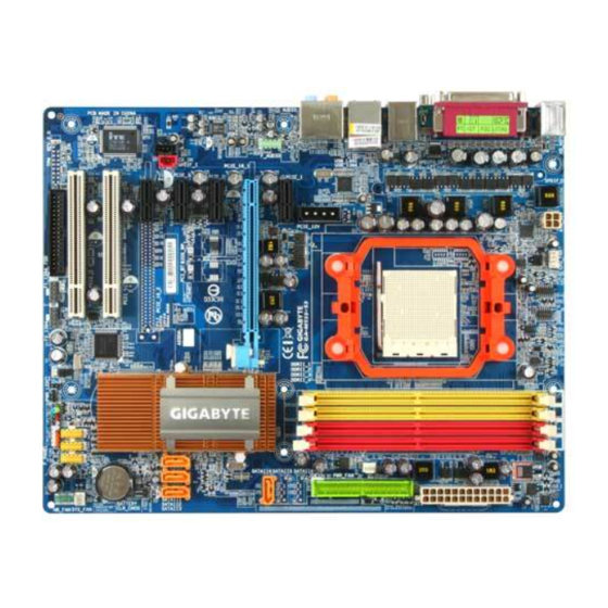
Page 7: Ga-M55S-S3 Motherboard Layout
GA-M55S-S3 Motherboard Layout CPU_FAN KB_MS ATX_12V SPDIF_O SPDIFO_OPT Socket AM2 IDE1 Marvell 88E1116 AUDIO PCIE_12V CPU_FAN GA-M55S-S3 F_AUDIO PCIE_1 SATAII4 PCIE_16_1 CODEC BIOS nVIDIA ® PCIE_2 nForce 550 CD_IN PCIE_3 CLR_CMOS PCIE_4 BATTERY PCI1 TSB43AB23 PCI2 SYS_FAN F_PANEL F1_1394 F2_1394 PWR_LED F_USB3 F_USB1... -
Page 8: Block Diagram
Block Diagram CPUCLK+/-(200MHz) Socket AM2 DDRII 800/667/533MHz DIMM Dual Channel Memory PCI-ECLK Hyper Transport Bus (100MHz) RJ45 PCI Express x16 Marvell 88E1116 PCI Express Bus nVIDIA ® BIOS nForce 550 PCI-ECLK 4 SATA 3Gb/s (100MHz) ATA33/66/100/133 IDE Channel 4 PCI Express x1 Floppy PCI Bus LPC BUS... -
Page 9: Chapter 1 Hardware Installation
Chapter 1 Hardware Installation Considerations Prior to Installation Preparing Your Computer The motherboard contains numerous delicate electronic circuits and components which can become damaged as a result of electrostatic discharge (ESD). Thus, prior to installation, please follow the instructions below: 1. -
Page 10: Feature Summary
Feature Summary Socket AM2 for AMD Athlon 64 FX / Athlon 64 X2 Dual-Core / Athlon 64 / Sempron processor Front Side Bus 2000MHz Chipset nVIDIA nForce 550 ® Marvell 88E1116 phy (10/100/1000Mbit) Audio Onboard Realtek ALC883 CODEC chip Supports High Definition Audio... - Page 11 Rear Panel I/O 1 PS/2 keyboard port 1 PS/2 mouse port 1 parallel port 1 SPDIF out port (coaxial) 1 SPDIF out port (optical) 1 serial port (COMA) 4 USB 2.0/1.1 ports 1 IEEE1394 port 1 RJ-45 port 6 audio jacks (Line In / Line Out / MIC In / Surround Speaker Out (Rear Speaker Out) / Center/Subwoofer Speaker Out / Side Speaker Out) I/O Control IT8716 chip...
-
Page 12: Installation Of The Cpu And Cpu Cooler
Installation of the CPU and CPU Cooler Before installing the CPU, please comply with the following conditions: 1. Please make sure that the motherboard supports the CPU. 2. Please take note of the pin 1 marking (the small triangle) on the CPU. If you install the CPU in the wrong direction, the CPU will not insert properly. -
Page 13: Installation Of The Cpu Cooler
1-3-2 Installation of the CPU Cooler Fig.1 Before installing the CPU cooler, please first add an even layer of heat paste on the surface of the CPU. Install all the CPU cooler components (Please refer to the cooler manual for detailed installation instructions). Fig.2 Please connect the CPU cooler power connector to the CPU_FAN con- nector located on the motherboard so that the CPU cooler can properly... -
Page 14: Installation Of Memory
Installation of Memory Before installing the memory modules, please comply with the following conditions: Please make sure that the memory used is supported by the motherboard. It is recommended that memory of similar capacity, specifications and brand be used. Before installing or removing memory modules, please make sure that the computer power is switched off to prevent hardware damage. - Page 15 Dual Channel Memory Configuration The GA-M55S-S3 supports the Dual Channel Technology. After operating the Dual Channel Technology, the bandwidth of Memory Bus will double. Due to CPU limitation, if you wish to operate the Dual Channel Technology, follow the guidelines below: 1.
-
Page 16: Installation Of Expansion Cards
Installation of Expansion Cards You can install your expansion card by following the steps outlined below: Read the related expansion card's instruction document before install the expansion card into the computer. Remove your computer's chassis cover, screws and slot bracket from the computer. Press the expansion card firmly into expansion slot in motherboard. -
Page 17: I/O Back Panel Introduction
I/O Back Panel Introduction PS/2 Keyboard and PS/2 Mouse Connector To install a PS/2 port keyboard and mouse, plug the mouse to the upper port (green) and the keyboard to the lower port (purple). Parallel Port The parallel port allows connection of a printer, scanner and other peripheral devices. SPDIF_O (COATIAL) The SPDIF coaxial output port is capable of providing digital audio to external speakers or compressed AC3 data to an external Dolby Digital Decoder via a coaxial cable. -
Page 18: Connectors Introduction
Line In The default Line In jack. Devices like CD-ROM, walkman etc. can be connected to Line In jack. Line Out (Front Speaker Out) The default Line Out (Front Speaker Out) jack. Stereo speakers, earphone or front surround speakers can be connected to Line Out (Front Speaker Out) jack. MIC In The default MIC In jack. - Page 19 1/2) ATX_12V / ATX (Power Connector) With the use of the power connector, the power supply can supply enough stable power to all the components on the motherboard. Before connecting the power connector, please make sure that all components and devices are properly installed. Align the power connector with its proper location on the motherboard and connect tightly.
- Page 20 3) PCIE_12V (Power Connector) The PCIE_12V power connector supplies extra power to the PCIE x16 slot. Connect this connector depending on your system requirements. PIin No. Definition +12V 4/5/6) CPU_FAN / SYS_FAN / PWR_FAN (Cooler Fan Power Connector) The cooler fan power connector supplies a +12V power voltage via a 3-pin/4-pin (only for CPU_FAN) power connector and possesses a foolproof connection design.
- Page 21 7) FDD (FDD Connector) The FDD connector is used to connect the FDD cable while the other end of the cable connects to the FDD drive. The types of FDD drives supported are: 360KB, 720KB, 1.2MB, 1.44MB and 2.88MB. Before attaching the FDD cable, please take note of the foolproof groove in the FDD connector.
- Page 22 9) SATAII1 / 2 / 3 / 4 (SATA 3Gb/s Connectors, Controlled by nForce 550) SATA 3Gb/s can provide up to 300MB/s transfer rate. Please refer to the BIOS setting for the SATA 3Gb/s and install the proper driver in order to work properly. Pin No.
- Page 23 11) F_PANEL (Front Panel Jumper) Please connect the power LED, PC speaker, reset switch and power switch etc. of your chassis front panel to the F_PANEL connector according to the pin assignment below. Message LED/ Speaker Connector Power Power/ Switch Sleep LED Reset Switch IDE Hard Disk Active LED...
-
Page 24: Front Audio Connector
12) PWR_LED The PWR_LED connector is connected with the system power indicator to indicate whether the system is on/off. It will blink when the system enters suspend mode. Pin No. Definition MPD+ MPD- MPD- 13) F_AUDIO (Front Audio Connector) This connector supports either HD (High Definition) or AC97 front panel audio module. If you wish to use the front audio function, connect the front panel audio module to this connector. - Page 25 14) CD_IN (CD In Connector) Connect CD-ROM or DVD-ROM audio out to the connector. Pin No. Definition CD-L CD-R 15) SPDIF_I (SPDIF In Connector) Use SPDIF IN feature only when your device has digital output function. Be careful with the polarity of the SPDIF_I connector.
- Page 26 16) F_ USB1 / F_USB2 / F_USB3 (Front USB Connector) Be careful with the polarity of the front USB connector. Check the pin assignment carefully while you connect the front USB cable, incorrect connection between the cable and connector will make the device unable to work or even damage it.
- Page 27 18) CI (Chassis Intrusion, Case Open) This 2-pin connector allows your system to detect if the chassis cover is removed. You can check the "Case Opened" status in BIOS Setup. Pin No. Definition Signal 19) CLR_CMOS (Clear CMOS) You may clear the CMOS data to its default values by this header. To clear CMOS, temporarily short the two pins.
- Page 28 GA-M55S-S3 Motherboard - 28 -...
-
Page 29: Chapter 2 Bios Setup
Chapter 2 BIOS Setup BIOS (Basic Input and Output System) includes a CMOS SETUP utility which allows user to configure required settings or to activate certain system features. The CMOS SETUP saves the configuration in the CMOS SRAM of the motherboard. When the power is turned off, the battery on the motherboard supplies the necessary power to the CMOS SRAM. -
Page 30: The Main Menu (For Example: Bios Ver. : E6)
<F12> : For Boot Menu Select boot sequence for onboard (or add-on cards) device. Boot Menu == Select a Boot First device == Award Modular BIOS v6.00PG, An Energy Star Ally Floppy Copyright (C) 1984-2006, Award Software, Inc. LS120 M55S-S3 E6 Hard Disk CDROM USB-FDD... - Page 31 Standard CMOS Features This setup page includes all the items in standard compatible BIOS. Advanced BIOS Features This setup page includes all the items of Award special enhanced features. Integrated Peripherals This setup page includes all onboard peripherals. Power Management Setup This setup page includes all the items of Green function features.
-
Page 32: Standard Cmos Features
Standard CMOS Features CMOS Setup Utility-Copyright (C) 1984-2006 Award Software Standard CMOS Features Date (mm:dd:yy) Fri, Jun 23 2006 Item Help Time (hh:mm:ss) 9:45:15 Menu Level IDE Channel 0 Master [None] Change the day, month, IDE Channel 0 Slave [None] year IDE Channel 2 Master [None]... - Page 33 Access Mode Use this to set the access mode for the hard drive. The two options are: Large/Auto(default:Auto) Capacity Capacity of currently installed hard drive. Hard drive information should be labeled on the outside drive casing. Enter the appropriate option based on this information.
-
Page 34: Advanced Bios Features
Advanced BIOS Features CMOS Setup Utility-Copyright (C) 1984-2006 Award Software Advanced BIOS Features Hard Disk Boot Priority [Press Enter] Item Help First Boot Device [Floppy] Menu Level Second Boot Device [Hard Disk] Third Boot Device [CDROM] Select Hard Disk Boot Boot Up Floppy Seek [Disabled] Device Priority... - Page 35 Password Check System The system can not boot and can not access to Setup page will be denied if the correct password is not entered at the prompt. Setup The system will boot, but access to Setup will be denied if the correct password is not entered at the prompt.
-
Page 36: Integrated Peripherals
Integrated Peripherals CMOS Setup Utility-Copyright (C) 1984-2006 Award Software Integrated Peripherals Serial-ATA RAID Config [Press Enter] Item Help On-Chip IDE Channel0 [Enabled] Menu Level On-Chip MAC Lan [Auto] NV Serial-ATA Controller [All Enabled] IDE Prefetch Moed [Enabled] Onboard Audio Function [Auto] SMART LAN [Press Enter]... - Page 37 NV SATA 2 Secondary RAID Enabled Enable RAID function for the second channel of the second SATA controller. (Default value) Disabled Disable the RAID function of this channel. It will operate in ATA mode. On-Chip IDE Channel0 Enabled Enable onboard first channel IDE port. (Default value) Disabled Disable onboard first channel IDE port.
- Page 38 When LAN Cable Is Functioning Normally... 1. If no cable problem is detected on the LAN cable connected to a Gigabit hub, the Status fields of Pair 1-2, Pair 3-6, Pair 4-5, and Pair 7-8 will show Normal and the Length fields will show N/A, as shown in the figure above.
- Page 39 ECP Mode Use DMA This item will become available when Parallel Port Mode set to ECP or ECP+EPP. Set ECP Mode Use DMA to 3. (Default value) Set ECP Mode Use DMA to 1. On-Chip USB V1.1+V2.0 Enable USB 1.1 and USB 2.0 controllers. (Default value) V1.1 Enable only USB 1.1 controller Disabled...
-
Page 40: Power Management Setup
Power Management Setup CMOS Setup Utility-Copyright (C) 1984-2006 Award Software Power Management Setup ACPI Suspend Type [S1(POS)] Item Help Soft-Off by Power button [Instant-Off] Menu Level PME Event Wake Up [Enabled] Modem Ring On [Disabled] USB Resume from Suspend [Disabled] Power-On by Alarm [Disabled] x Day of Month Alarm... - Page 41 Power On By Mouse Disabled Disabled this function. (Default value) Double-Click Double click on PS/2 mouse left button to power on the system. Power On By Keyboard Disabled Disabled this function. (Default value) Password Enter from 1 to 5 characters to set the Keyboard Power On Password. Any KEY Press any key to power on the system.
-
Page 42: Pnp/Pci Configurations
PnP/PCI Configurations CMOS Setup Utility-Copyright (C) 1984-2006 Award Software PnP/PCI Configurations PCI 2 IRQ Assignment [Auto] Item Help PCI 1 IRQ Assignment [Auto] Menu Level : Move Enter: Select +/-/PU/PD: Value F10: Save ESC: Exit F1: General Help F5: Previous Values F6: Fail-Safe Defaults F7: Optimized Defaults PCI 2 IRQ Assignment... -
Page 43: Pc Health Status
PC Health Status CMOS Setup Utility-Copyright (C) 1984-2006 Award Software PC Health Status Reset Case Open Status [Disabled] Item Help Case Opened Menu Level Vcore DDR18V +3.3V +12V Current CPU Temperature Current CPU FAN Speed 3245 RPM Current POWER FAN Speed 0 RPM Current SYSTEM FAN Speed 0 RPM... - Page 44 CPU Smart FAN Control (Note) Disabled Disable this function. Enabled When this function is enabled, CPU fan will run at different speed depending on CPU temperature. Users can adjust the fan speed with Easy Tune based on their requirements. (Default value) CPU Smart FAN Mode This option is available only when CPU Smart FAN Control is enabled.
-
Page 45: Mb Intelligent Tweaker(M.i.t.)
MB Intelligent Tweaker(M.I.T.) CMOS Setup Utility-Copyright (C) 1984-2006 Award Software MB Intelligent Tweaker(M.I.T.) CPU Frequency (MHz) [Auto] Item Help PCIE Clock (MHz) [Auto] Menu Level CPU Clock Ratio [Auto] DDR2 Voltage Control [Normal] Chipset/PCIE Voltage [Normal] HT-Link Voltage [Normal] CPU HT-Link Voltage [Normal] CPU Voltage Control [Normal]... - Page 46 CPU HT-Link Voltage Set the voltage settings for the HT-Link between CPU and chipset. Normal Set CPU HT-Link voltage to Normal. (Default value) +0.025V ~ +0.375V Set CPU HT-Link voltage from +0.025V to +0.375V. CPU Voltage Control Please note that by overclocking your system through the increase of the CPU voltage, damage to the CPU or decrease in the CPU life expectancy may occur.
-
Page 47: Load Fail-Safe Defaults
Load Fail-Safe Defaults CMOS Setup Utility-Copyright (C) 1984-2006 Award Software CMOS Setup Utility-Copyright (C) 1984-2006 Award Software Standard CMOS Features Load Fail-Safe Defaults Advanced BIOS Features Load Optimized Defaults Integrated Peripherals Set Supervisor Password Power Management Setup Set User Password Load Fail-Safe Defaults (Y/N)? N PnP/PCI Configurations Save &... -
Page 48: Set Supervisor/User Password
2-10 Set Supervisor/User Password CMOS Setup Utility-Copyright (C) 1984-2006 Award Software Standard CMOS Features Load Fail-Safe Defaults Advanced BIOS Features Load Optimized Defaults Integrated Peripherals Set Supervisor Password Power Management Setup Set User Password PnP/PCI Configurations Save & Exit Setup Enter Password: PC Health Status Exit Without Saving... -
Page 49: Save & Exit Setup
2-11 Save & Exit Setup CMOS Setup Utility-Copyright (C) 1984-2006 Award Software Standard CMOS Features Load Fail-Safe Defaults Advanced BIOS Features Load Optimized Defaults Integrated Peripherals Set Supervisor Password Power Management Setup Set User Password Save to CMOS and EXIT (Y/N)? Y PnP/PCI Configurations Save &... - Page 50 GA-M55S-S3 Motherboard - 50 -...
-
Page 51: Chapter 3 Drivers Installation
Chapter 3 Drivers Installation Pictures below are shown in Windows XP. Insert the driver CD-title that came with your motherboard into your CD-ROM drive, the driver CD-title will auto start and show the installation guide. If not, please double click the CD-ROM device icon in "My computer", and execute the Run.exe. -
Page 52: Software Applications
Software Applications This page displays all the tools that Gigabyte developed and some free software, you can choose anyone you want and press "install" to install them. Driver CD Information This page lists the contents of software and drivers in this CD-title. GA-M55S-S3 Motherboard - 52 -... -
Page 53: Hardware Information
Hardware Information This page lists all device you have for this motherboard. Contact Us Please see the last page for details. - 53 - Drivers Installation... - Page 54 GA-M55S-S3 Motherboard - 54 -...
-
Page 55: Chapter 4 Appendix
Chapter 4 Appendix Unique Software Utilities (Not all model support these Unique Software Utilities, please check your MB features.) 4-1-1 EasyTune 5 Introduction EasyTune 5 presents the most convenient Windows based system performance enhancement and manageability utility. Featuring several powerful yet easy to use tools such as 1) Overclocking for enhancing system performance, 2) C.I.A. -
Page 56: Xpress Recovery2 Introduction
4-1-2 Xpress Recovery2 Introduction Xpress Recovery2 is designed to provide quick backup and restora- tion of hard disk data. Supporting Microsoft operating systems including Windows XP/2000/NT/98/Me and DOS, and file systems including FAT16, FAT32, and NTFS, Xpress Recovery2 is able to back up data on hard disks on PATA and SATA IDE controllers. - Page 57 The Main Screen of Xpress Recovery2 1. RESTORE: Restore the backed-up data to your hard disk. (This button will not appear if there is no backup file.) 2. BACKUP: Back up data from hard disk. 3. REMOVE: Remove previously-created backup files to release disk space.
-
Page 58: Flash Bios Method Introduction
4-1-3 Flash BIOS Method Introduction Method 1 : Q-Flash Utility Q-Flash is a BIOS flash utility embedded in Flash ROM. With this utility, users only have to stay in the BIOS menu when they want to update BIOS. Q-Flash allows users to flash BIOS without any utility in DOS or Windows. - Page 59 Entering the Q-Flash utility: Step1: To use Q-Flash utility, you must press Del in the boot screen to enter BIOS menu. CMOS Setup Utility-Copyright (C) 1984-2004 Award Software Standard CMOS Features Select Language Advanced BIOS Features Load Fail-Safe Defaults Integrated Peripherals Load Optimized Defaults Power Management Setup Set Supervisor Password...
- Page 60 Using the Q-Flash utility: This section tells you how to update BIOS using the Q-Flash utility. As described in the "Before you begin" section above, you must prepare a floppy disk having the BIOS file for your motherboard and insert it to your computer.
- Page 61 3. Press Y button on your keyboard after you are sure to update BIOS. Then it will begin to update BIOS. The progress of updating BIOS will be displayed. Please do not take out the floppy disk when it begins flashing BIOS. 4.
- Page 62 Press Del to enter BIOS menu after system reboots. When you are in BIOS menu, move to Load Optimized Defaults item and press Enter to load BIOS Optimized Defaults. Normally the system redetects all devices after BIOS has been upgraded. Therefore, we highly recommend reloading the BIOS defaults after BIOS has been upgraded.
- Page 63 Exploring the Q-Flash utility screen The Q-FlashBIOS utility screen consists of the following key components. Q-Flash utility bar Q-Flash Utility V1.30 Flash Type/Size.........SST 49LF003A 256K Keep DMI Data Enable Task menu for Update BIOS from Floppy Q-Flash utility Save BIOS to Floppy Action bar Enter : Run :Move...
- Page 64 Press Y button on your keyboard after you are sure to update BIOS. Then it will begin to update BIOS. The progress of updating BIOS will be shown at the same time. Q-Flash Utility V1.30 Flash Type/Size.........SST 49LF003A 256K Keep DMI Data Enable Do not turn off power or Updating BIOS Now...
-
Page 65: @Bios Utility
Method 2 : @BIOS Utility If you do not have a DOS startup disk, we recommend that you use the new @BIOS utility. @BIOS allows users to update their BIOS under Windows. Just select the desired @BIOS server to download the latest version of BIOS. - Page 66 III. Save BIOS In the very beginning, there is "Save Current BIOS" icon shown in dialog box. It means to save the current BIOS version. IV. Check out supported motherboard and Flash ROM: In the very beginning, there is "About this program" icon shown in dialog box. It can help you check out which kind of motherboard and which brand of Flash ROM are supported.
-
Page 67: Configuring Sata Hard Drive(S)
4-1-4 Configuring SATA Hard Drive(s) To configure SATA hard drive(s), follow the steps below: (1) Install SATA hard drive(s) in your system. (2) Configure SATA controller mode and boot sequence in BIOS Setup. (3) Configure RAID set in RAID BIOS. (Note) (4) Make a floppy disk containing the SATA controller driver. - Page 68 (2) Configuring SATA controller mode and boot sequence in BIOS Setup You have to make sure whether the SATA controller is configured correctly in system BIOS Setup and set BIOS boot sequence for the SATA hard drive(s)/RAID array. Step 1: Turn on your computer and press Del to enter BIOS Setup during POST (Power-On Self Test).
- Page 69 Step 2: To boot from Windows installation CD-ROM, set First Boot Device under the Advanced BIOS Features menu to CDROM (Figure 3). CMOS Setup Utility-Copyright (C) 1984-2006 Award Software Advanced BIOS Features Hard Disk Boot Priority [Press Enter] Item Help First Boot Device [CDROM] Menu Level...
- Page 70 (3) Configuring RAID set in RAID BIOS Enter the RAID BIOS setup utility to configure a RAID array. Skip this step and proceed to Section 4 if you do not want to create RAID. Step 1: After the POST memory test begins and before the operating system boot begins, look for a message which says "Press F10 to enter RAID setup utility"...
- Page 71 Step 5: Next, select the hard drives which you wish to be included in the disk array. The Free Disks section displays the information about the currently installed SATA hard drives. Press the TAB key to move to the Free Disks section. Select the target hard drives using the UP or DOWN ARROW key and use the RIGHT ARROW key to add the hard drives to the Array Disks section (Figure 6).
- Page 72 After that, the Array List screen displaying the RAID array you created will appear (Figure 8). If you want to set the disk array as boot device, use the UP or DOWN ARROW key to select the array and press B. The Boot section will show Yes. MediaShield Utility Mar 22 2006 - Array List - Boot...
- Page 73 (4) Making a SATA Driver Disk To install operating system onto a serial ATA hard disk successfully, you need to install the SATA controller driver during OS installation. Without the driver, the hard disk may not be recognized during the Windows setup process. First of all, copy the driver for the SATA controller from the motherboard driver CD-ROM to a floppy disk.
- Page 74 (5) Installing SATA controller driver during OS installation Now that you have prepared the SATA driver disk and configured BIOS settings, you are ready to install Windows 2000/XP onto your SATA hard drive with the SATA driver. The following is an example of Windows XP installation.
- Page 75 Step 3: If Setup correctly recognizes the driver in the floppy disk, a controller menu similar to Figure 15 below will appear. Use the ARROW keys to select NVIDIA RAID CLASS DRIVER* (Figure 15) and press ENTER. Later, when a screen similar to Figure 16 appears, you must press S to select additional driver.
- Page 76 Step 4: When the next screen (Figure 17) appears, press ENTER to continue the SATA driver installation from the floppy disk. Windows Setup Setup will load support for the following mass storage device(s): NVIDIA RAID CLASS DRIVER (required) NVIDIA NForce Storage Controller (required) * To specify additional SCSI adapters, CD-ROM drives, or special disk controllers for use with Windows, including those for which you have a device support disk from a mass storage device...
- Page 77 (6) Configuring a bootable RAID array with Microsoft Windows 2000 Problem: Users cannot install Windows 2000 with Service Pack 2 (or previous versions) to a bootable RAID volume. There are two solutions to resolve this issue. Solutions 1: Use the NVRAID tool (nForce Driver Version 5.xx) to convert the boot volume to a RAID array. Here are the detailed step-by-step instructions: Step 1: Install Windows 2000 onto a selected hard drive.
- Page 78 Step 3: After system restarts, press F10 to enter the NVIDIA RAID setup utility. Select Striping in the RAID Mode filed (Figure 21). Move to the Free Disks section with the TAB key. Select the desired disk and use the RIGHT ARROW key to add it to Array Disks menu.
- Page 79 Step 5: Install the NVIDIA nForce Driver Package while in Windows 2000 and reboot the system. Go to START> Programs>Nvidia Corporation and select NVRAID manager. You should see the single disk RAID array (in striping mode) that was created from the boot disk. Select the single boot disk RAID Array by clicking on it.
-
Page 80: 4- / 6- / 8- Channel Audio Function Introduction
4-1-5 2- / 4- / 6- / 8- Channel Audio Function Introduction The default speaker settings for the 6 audio jacks are as shown in the picture to the right. The jack retasking capability supported by HD Audio allows Center/Subwoofer Line In Speaker Out users to change the function for each audio jack by... - Page 81 STEP 2: In the Audio Control Panel, click the Audio I/O tab. In the upper left list, click 2CH Speaker. STEP 3: After a speaker or headphone is plugged into the rear Line Out jack, a small window will pop up and ask you what type of equipment is connected.
- Page 82 STEP 3: After plugging in 4-channel speakers to the rear speaker jacks, a small window will pop up and ask you what type of equipment is connected. Choose a device depending on the type of speaker connected (4-channel audio consists of Front Speaker Out (Line Out) and Rear Speaker Out) and then click OK.
- Page 83 8 Channel Audio Setup STEP 1 : After installation of the audio driver, you should find an Audio Manager icon in your system tray (you can also find the icon in Control Panel). Double- click the icon to open the Audio Control Panel. STEP 2: In the Audio Control Panel, click the Audio I/O tab.
- Page 84 Sound Effect Configuration: At the Sound Effect menu, users can adjust sound option settings as desired. AC'97 Audio Configuration: To enable the front panel audio connector to sup- port AC97 Audio mode, go to the Audio Control Panel and click the Audio I/O tab. In the ANA- LOG area, click the Tool icon and then select the Disable front panel jack detection check box.
-
Page 85: Troubleshooting
Troubleshooting Below is a collection of general asked questions. To check general asked questions based on a specific motherboard model, please log on to GIGABYTE's website. Question 1: I cannot see some options that were included in previous BIOS after updating BIOS. Why? Answer: Some advanced options are hidden in new BIOS version. - Page 86 GA-M55S-S3 Motherboard - 86 -...
- Page 87 Contact Us Taiwan (Headquarters) China GIGA-BYTE TECHNOLOGY CO., LTD. NINGBO G.B.T. TECH. TRADING CO., LTD. Address: No.6, Bau Chiang Road, Hsin-Tien, WEB address : http://www.gigabyte.cn Taipei 231, Taiwan Shanghai TEL: +886-2-8912-4888 TEL: +86-21-63410999 FAX: +886-2-8912-4003 FAX: +86-21-63410100 Tech. and Non-Tech. Support (Sales/Marketing) : Beijing http://ggts.gigabyte.com.tw TEL: +86-10-62102838...
- Page 88 Germany Russia G.B.T. TECHNOLOGY TRADING GMBH Moscow Representative Office Of GIGA-BYTE Technology WEB address : http://www.gigabyte.de Co., Ltd. U.K. WEB address : http://www.gigabyte.ru G.B.T. TECH. CO., LTD. Latvia WEB address : http://www.giga-byte.co.uk GIGA-BYTE Latvia The Netherlands WEB address : http://www.gigabyte.com.lv GIGA-BYTE TECHNOLOGY B.V.
Need help?
Do you have a question about the GA-M55S-S3 and is the answer not in the manual?
Questions and answers