Table of Contents
Advertisement
Advertisement
Table of Contents

Related Manuals for Asus P4P800


Summary of Contents for Asus P4P800
- Page 1 P4P800 User Guide...
- Page 2 Product warranty or service will not be extended if: (1) the product is repaired, modified or altered, unless such repair, modification of alteration is authorized in writing by ASUS; or (2) the serial number of the product is defaced or missing.
-
Page 3: Table Of Contents
How this guide is organized ..........viii Conventions used in this guide ..........ix Where to find more information ..........ix ASUS contact information ............... x P4P800 specifications summary ............ xi Chapter 1: Product introduction 1.1 Welcome! ................1-1 1.2 Package contents ............... 1-1 1.3 Special features .............. - Page 4 Using AFUDOS to update the BIOS ...... 4-1 4.1.3 Using AFUDOS to copy BIOS from PC ....4-3 4.1.4 Using ASUS EZ Flash to update the BIOS .... 4-4 4.1.5 Recovering the BIOS with CrashFree BIOS 2 ..4-5 4.2 BIOS Setup program ............4-7 4.2.1...
- Page 5 5.2.1 Running the support CD ........5-1 5.2.2 Drivers menu ............5-2 5.2.3 Utilities menu ............5-3 5.2.4 ASUS Contact Information ........5-4 5.2.5 Other information ........... 5-5 5.3 Software information ............5-7 5.3.1 ASUS Update ............5-7 5.3.2 ASUS MyLogo2™ ..........5-8 5.3.3...
-
Page 6: Fcc/Cdc Statements
FCC/CDC statements Federal Communications Commission Statement This device complies with FCC Rules Part 15. Operation is subject to the following two conditions: • This device may not cause harmful interference, and • This device must accept any interference received including interference that may cause undesired operation. -
Page 7: Safety Information
Safety information Electrical safety • To prevent electrical shock hazard, disconnect the power cable from the electrical outlet before relocating the system. • When adding or removing devices to or from the system, ensure that the power cables for the devices are unplugged before the signal cables are connected. -
Page 8: About This Guide
How this guide is organized This manual contains the following parts: • Chapter 1: Product introduction This chapter describes the features of the P4P800 motherboard. It includes brief descriptions of the special attributes of the motherboard and the new technology it supports. -
Page 9: Conventions Used In This Guide
1. ASUS Websites The ASUS websites worldwide provide updated information on ASUS hardware and software products. The ASUS websites are listed in the ASUS Contact Information on page x. 2. Optional Documentation Your product package may include optional documentation, such as warranty flyers, that may have been added by your dealer. -
Page 10: Asus Contact Information
General Support: +1-502-995-0883 Notebook Support: +1-510-739-3777 x5110 Web Site: usa.asus.com Support Email: tsd@asus.com ASUS COMPUTER GmbH (Germany and Austria) Address: Harkortstr. 25, 40880 Ratingen, BRD, Germany General Email: sales@asuscom.de (for marketing requests only) General Fax: +49-2102-9599-31 Technical Support Support Hotlines:... -
Page 11: P4P800 Specifications Summary
P4P800 specifications summary ® ® Socket 478 for Intel Pentium 4 / Celeron up to 3.2 GHz+ Supports Intel ® Hyper-Threading Technology ® Supports Intel Prescott CPU Chipset North Bridge: Intel 82865PE South Bridge: Intel ICH5R w/ RAID 0 support... - Page 12 Front panel audio connector COM2 connector BIOS features 4Mb Flash ROM, AMI BIOS, PnP, DMI2.0, ACPI, SM BIOS2.3, CrashFree BIOS 2, Multi-language BIOS, ASUS EZ Flash, ASUS MyLogo2, ASUS Instant Music Internal I/O Industry standard USB 2.0, PCI 2.2 (PCI 2.3) Manageability DMI 2.0, WOL/WOR by PME, WO_USB, WO_KB/MS,...
-
Page 13: Chapter 1: Product Introduction
Chapter 1 This chapter describes the features of the P4P800 motherboard. It includes brief explanations of the special attributes of the motherboard and the new technology it supports. Product introduction... - Page 14 Chapter summary Welcome! ............1-1 Package contents .......... 1-1 Special features ..........1-2 Motherboard overview ........1-7 ASUS P4P800 motherboard...
-
Page 15: Welcome
Supporting up to 4GB of system memory with PC3200/2700/2100 DDR SDRAM, high-resolution graphics via an AGP 8X slot, Serial ATA support, USB 2.0, and 6-channel audio features, the P4P800 is your perfect tool to get ahead in the world of power computing! Before you start installing the motherboard, and hardware devices on it, check the items in your package with the list below. -
Page 16: Special Features
Dual Channel DDR memory support Employing the dual channel Double Data Rate (DDR) memory architecture, the P4P800 motherboard supports up to 4GB of system memory using PC3200/2700/PC2100 DDR DIMMs. The ultra-fast 400MHz memory bus double the bandwidth to a maximum of 6.4GB/s that delivers the required bandwidth for the latest 3D graphics, multimedia, and Internet applications. -
Page 17: Asus Mylogo2
BIOS automatically restores the previous values of the CPU parameters. ASUS MyLogo2™ This new feature present in the P4P800 motherboard allows you to personalize and add style to your system with customizable boot logos. See details on page 5-8. -
Page 18: Instant Music
ASUS EZ Flash BIOS With the ASUS EZ Flash, you can easily update the system BIOS even before loading the operating system. No need to use a DOS-based utility or boot from a floppy disk. See details on page 4-4. -
Page 19: Value-Added Solutions
ASUS update This utility allows you to update the motherboard BIOS through a user- friendly interface. Connect to the Internet then to the ASUS FTP site nearest you to obtain the latest BIOS version for your motherboard. ASUS P4P800 motherboard user guide... -
Page 20: Motherboard Overview
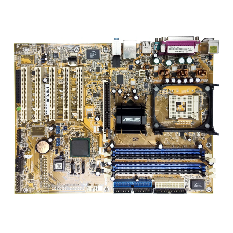
1.4.1 Major components The following are the major components of the P4P800 motherboard as pointed out in the picture on page 1-7. ATX 12V connector 15. - Page 21 ASUS P4P800 motherboard user guide...
-
Page 22: Core Specifications
1.4.2 Core specifications ATX 12V connector. This power connector connects the 4-pin 12V plug from the ATX 12V power supply. CPU socket. A 478-pin surface mount, Zero Insertion Force (ZIF) socket for the Intel Pentium 4 Processor (and Intel’s future Prescott ®... - Page 23 RJ-45 port. This port allows connection to a Local Area Network (LAN) through a network hub. Line In jack. This Line In (light blue) jack connects a tape player or other audio sources. In 6-channel mode, the function of this jack becomes Rear Speaker Out. ASUS P4P800 motherboard user guide...
- Page 24 Line Out jack. This Line Out (lime) jack connects a headphone or a speaker. In 6-channel mode, the function of this jack becomes Front Speaker Out. Microphone jack. This Mic (pink) jack connects a microphone. In 6- channel mode, the function of this jack becomes Bass/Center Speaker Out.
-
Page 25: Chapter 2: Hardware Information
Chapter 2 This chapter describes the hardware setup procedures that you have to perform when installing system components. It includes details on the switches, jumpers, and connectors on the motherboard. Hardware information... - Page 26 Chapter summary Motherboard installation ....... 2-1 Motherboard layout ........2-2 Before you proceed ........2-3 Central Processing Unit (CPU) ..... 2-4 System memory ........... 2-10 Expansion slots ........... 2-15 Jumpers ............2-20 Connectors ........... 2-23 ASUS P4P800 motherboard...
-
Page 27: Motherboard Installation
Motherboard installation Before you install the motherboard, study the configuration of your chassis to ensure that the motherboard fits into it. The P4P800 uses the ATX form factor that measures 12 inches x 9.6 inches. Make sure to unplug the power cord before installing or removing the motherboard. -
Page 28: Motherboard Layout
SATA1 Intel PCI1 ICH5R SATA2 AUX1 MODEM1 PCI2 USBPW56 USBPW78 4Mbit Firmware CLRTC1 Audio PCI3 Codec USB_56 USB_78 P4P800 FP_AUDIO CR2032 3V Lithium Cell PCI4 CMOS Power SPDIF_OUT PCI5 COM2 CHASSIS1 SB_PWR1 PANEL1 GAME1 WIFI SMB1 Chapter 2: Hardware information... -
Page 29: Before You Proceed
SB_PWR1 ® P4P800 Standby Powered Power P4P800 Onboard LED ASUS P4P800 motherboard user guide... -
Page 30: Central Processing Unit (Cpu)
Central Processing Unit (CPU) 2.4.1 Overview The motherboard comes with a surface mount 478-pin Zero Insertion ® ® Force (ZIF) socket. The socket is designed for the Intel Pentium Processor in the 478-pin package with 512KB L2 cache on 0.13 micron ®... -
Page 31: Installing The Cpu
Make sure that the socket lever is lifted up to 90°-100° angle, otherwise the CPU does not fit in completely. Incorrect installation of the CPU into the socket may bend the pins and severely damage the CPU! ASUS P4P800 motherboard user guide... - Page 32 3. Position the CPU above the Gold Mark socket such that its marked corner matches the base of the socket lever. 4. Carefully insert the CPU into the socket until it fits in place. The CPU fits only in one correct orientation. DO NOT force the CPU into the socket to prevent bending the pins and damaging the CPU! 5.
-
Page 33: Installing The Heatsink And Fan
Your boxed Intel Pentium 4 Processor package should come with installation instructions for the CPU, heatsink, and the retention mechanism. If the instructions in this section do not match the CPU documentation, follow the latter. ASUS P4P800 motherboard user guide... - Page 34 2. Position the fan with the retention mechanism on top of the heatsink. Align and snap the four hooks of the retention mechanism to the holes on each corner of the module base. Make sure that the fan and retention mechanism assembly perfectly fits the heatsink and module base, otherwise you cannot snap the hooks into the holes.
-
Page 35: Connecting The Cpu Fan Cable
CPU fan cable to the connector on the motherboard labeled CPU_FAN. CPU Fan Connector (CPU_FAN) Don’t forget to connect the CPU fan connector! Hardware monitoring errors may occur if you fail to plug this connector. ASUS P4P800 motherboard user guide... -
Page 36: System Memory
The following figure illustrates the location of the DDR DIMM sockets. ® P4P800 P4P800 184-Pin DDR DIMM Sockets Notes on DDR technology The DDR SDRAM technology evolved from the mainstream PC66, PC100, PC133 memory known as Single Data Rate (SDR) SDRAM. DDR memory however, has the ability to perform two data operations in one clock cycle, thus providing twice the throughput of SDR memory. -
Page 37: Memory Configurations
3+GB (a little less than 4GB) due to ICH5R resource allocation. 7. Double-sided DDR DIMMs with X16 (databus width = 16-bit) memory chips are not supported due to chipset limitation. 8. It is recommended to use the blue DIMM slots first. ASUS P4P800 motherboard user guide 2-11... - Page 38 Table 1 Recommended memory configurations Sockets Mode DIMM_A1 DIMM_A2 DIMM_B1 DIMM_B2 Single-channel (1) Populated — — — — Populated — — — — Populated — — — — Populated Dual-channel* (1) Populated Populated — — Populated Populated — — (3) Populated Populated Populated Populated * Use only identical DDR DIMM pairs.
- Page 39 4 modules inserted into the blue and black slots as two pairs of Dual-channel memory configuration. Obtain DDR DIMMs only from ASUS qualified vendors for better system performance. Make sure to use only the tested and qualified DDR400 DIMMs listed above.
-
Page 40: Installing A Dimm
Follow these steps to install a DIMM. 1. Locate the DIMM sockets in the motherboard. ® P4P800 P4P800 184-Pin DDR DIMM Sockets DDR DIMM 2. Unlock a DIMM socket by pressing the retaining clips outward. 3. Align a DIMM on the socket such that the notch on the DIMM matches the break on the socket. -
Page 41: Expansion Slots
1. Turn on the system and change the necessary BIOS settings, if any. See Chapter 4 for information on BIOS setup. 2. Assign an IRQ to the card. Refer to the tables on the next page. 3. Install the software drivers for the expansion card. ASUS P4P800 motherboard user guide 2-15... -
Page 42: Standard Interrupt Assignments
Standard Interrupt Assignments Priority Standard Function System Timer Keyboard Controller Programmable Interrupt Communications Port (COM2) Communications Port (COM1) Sound Card (sometimes LPT2) Floppy Disk Controller Printer Port (LPT1) System CMOS/Real Time Clock ACPI Mode when used IRQ Holder for PCI Steering IRQ Holder for PCI Steering PS/2 Compatible Mouse Port Numeric Data Processor... -
Page 43: Pci Slots
SATA connectors. • When installing 64-bit PCI cards, it is recommended not to install in PCI slot 3. 64-bit PCI cards installed in PCI slot 3 may interfere with the USB connectors. ASUS P4P800 motherboard user guide 2-17... -
Page 44: Agp Slot
® P4P800 Keyed for 1.5v P4P800 Accelerated Graphics Port (AGP) If installing the ATi 9500 or 9700 Pro Series VGA cards, use only the card version PN xxx-xxxxx-30 or later, for optimum performance and overclocking stability. -
Page 45: Wifi Slot
2.6.5 Wi-Fi slot The Wi-Fi (Wireless Fidelity) slot will support the ASUS Wi-Fi module when available. Visit the ASUS website (www.asus.com) for product updates. The Wi-Fi slot conforms to the Institute of Electrical and Electronics Engineers (IEEE) 802.11b standard for wireless devices operating in the 2.4 GHz frequency band. -
Page 46: Jumpers
Clear CMOS P4P800 (Default) P4P800 Clear RTC RAM You do not need to clear the RTC when the system hangs due to overclocking. For system failure due to overclocking, use the C.P.R. (CPU Parameter Recall) feature. Shut down and reboot the system so BIOS can automatically reset parameter settings to default values. - Page 47 [Disabled]). This feature requires an ATX power supply that can supply at least 1A on the +5VSB lead and a corresponding setting in the BIOS. (see section 4.5.1 Power Up Control) KBPWR +5VSB (Default) ® P4P800 P4P800 Keyboard Power Setting ASUS P4P800 motherboard user guide 2-21...
- Page 48 ® USBPW56 USBPW78 P4P800 +5VSB P4P800 USB Device Wake Up (Default) 1. The USB device wake-up feature requires a power supply that can provide 500mA on the +5VSB lead for each USB port. Otherwise, the system would not power up.
- Page 49 1. Turn on the system and change the necessary BIOS settings, if any. See Chapter 4 for information on BIOS setup. 2. Assign an IRQ to the card. Refer to the tables on the next page. 3. Install the software drivers for the expansion card. ASUS P4P800 motherboard user guide 2-15...
- Page 50 Standard Interrupt Assignments Priority Standard Function System Timer Keyboard Controller Programmable Interrupt Communications Port (COM2) Communications Port (COM1) Sound Card (sometimes LPT2) Floppy Disk Controller Printer Port (LPT1) System CMOS/Real Time Clock ACPI Mode when used IRQ Holder for PCI Steering IRQ Holder for PCI Steering PS/2 Compatible Mouse Port Numeric Data Processor...
- Page 51 SATA connectors. • When installing 64-bit PCI cards, it is recommended not to install in PCI slot 3. 64-bit PCI cards installed in PCI slot 3 may interfere with the USB connectors. ASUS P4P800 motherboard user guide 2-17...
- Page 52 ® P4P800 Keyed for 1.5v P4P800 Accelerated Graphics Port (AGP) If installing the ATi 9500 or 9700 Pro Series VGA cards, use only the card version PN xxx-xxxxx-30 or later, for optimum performance and overclocking stability.
- Page 53 2.6.5 Wi-Fi slot The Wi-Fi (Wireless Fidelity) slot will support the ASUS Wi-Fi module when available. Visit the ASUS website (www.asus.com) for product updates. The Wi-Fi slot conforms to the Institute of Electrical and Electronics Engineers (IEEE) 802.11b standard for wireless devices operating in the 2.4 GHz frequency band.
-
Page 54: Clear Rtc Ram
Clear CMOS P4P800 (Default) P4P800 Clear RTC RAM You do not need to clear the RTC when the system hangs due to overclocking. For system failure due to overclocking, use the C.P.R. (CPU Parameter Recall) feature. Shut down and reboot the system so BIOS can automatically reset parameter settings to default values. - Page 55 [Disabled]). This feature requires an ATX power supply that can supply at least 1A on the +5VSB lead and a corresponding setting in the BIOS. (see section 4.5.1 Power Up Control) KBPWR +5VSB (Default) ® P4P800 P4P800 Keyboard Power Setting ASUS P4P800 motherboard user guide 2-21...
- Page 56 ® USBPW56 USBPW78 P4P800 +5VSB P4P800 USB Device Wake Up (Default) 1. The USB device wake-up feature requires a power supply that can provide 500mA on the +5VSB lead for each USB port. Otherwise, the system would not power up.
-
Page 57: Connectors
(Pin 5 is removed to prevent incorrect insertion when using ribbon cables with pin 5 plug). FLOPPY1 NOTE: Orient the red markings on ® the floppy ribbon cable to PIN 1. P4P800 PIN 1 P4P800 Floppy Disk Drive Connector ASUS P4P800 motherboard user guide 2-23... - Page 58 (usually zigzag) on the IDE ® ribbon cable to PIN 1. P4P800 PIN 1 P4P800 IDE Connectors For UltraDMA100/66 IDE devices, use an 80-conductor IDE cable. The UltraDMA/66 cable included in the motherboard package also supports UltraDMA100. Important notes when using legacy OS •...
- Page 59 • Only RAID 0 is supported. • Hot plug support for Serial ATA drive and connections are not available in this motherboard. ® • Install Windows XP™ Service Pack 1 when using Serial ATA. ASUS P4P800 motherboard user guide 2-25...
- Page 60 Parallel ATA and Serial ATA device configurations Following are the Parallel ATA and Serial ATA device configurations supported by Intel ICH5 specifications. Native operating systems (OS) are Windows 2000/XP. ICH5R supports a maximum of six (6) devices using these OS. Legacy OS are MS-DOS, Windows 98/Me/NT4.0.
- Page 61 By default, the pins labeled “Chassis Signal” and “Ground” are shorted with a jumper cap. If you wish to use the chassis intrusion detection feature, remove the jumper cap from the pins. CHASSIS1 ® P4P800 (Default) P4P800 Chassis Alarm Lead ASUS P4P800 motherboard user guide 2-27...
- Page 62 P4P800 12-Volt Fan Connectors 8. Power supply thermal connector (2-pin TRPWR1) If your power supply has a thermal monitoring feature, connect its thermal sensor cable to this connector. TRPWR1 ® P4P800 P4P800 Power Supply Thermal Connector 2-28 Chapter 2: Hardware information...
-
Page 63: Atx Power Connectors
ATXPWR1 ATX12V1 +12V DC GND +3.3VDC +3.3VDC -12.0VDC +3.3VDC PS_ON# +5.0VDC ® +12V DC GND +5.0VDC -5.0VDC PWR_OK +5.0VDC +5VSB P4P800 +5.0VDC +12.0VDC P4P800 ATX Power Connector ASUS P4P800 motherboard user guide 2-29... - Page 64 You must install the driver before you can use the USB 2.0 capability. ® P4P800 USB56 USB78 P4P800 USB 2.0 Header NEVER connect a 1394 cable to the USB_56 or USB_78 connectors. Doing so will damage the motherboard! The USB port is an optional item and not included in this motherboard package.
- Page 65 (such as a phone) and a mono_out (such as a speaker) between the audio and a voice modem card. MODEM Modem-Out Right Audio Channel Ground Ground ® Ground Ground Modem-In Left Audio Channel CD1(Black) AUX1(White) P4P800 P4P800 Internal Audio Connectors ASUS P4P800 motherboard user guide 2-31...
- Page 66 ® FP_AUDIO P4P800 P4P800 Front Panel Audio Connector 14. Digital Audio connector (6-1 pin SPDIF_OUT) This connector is for the S/PDIF audio module to allow digital sound output. Connect one end of the S/PDIF audio cable to this connector and the other end to the S/PDIF module.
- Page 67 • System Power LED Lead (3-1 pin PLED) This 3-1 pin connector connects to the system power LED. The LED lights up when you turn on the system power, and blinks when the system is in sleep mode. ASUS P4P800 motherboard user guide 2-33...
- Page 68 • System Warning Speaker Lead (4-pin SPKR) This 4-pin connector connects to the case-mounted speaker and allows you to hear system beeps and warnings. • System Management Interrupt Lead (2-pin SMI) This 2-pin connector allows you to manually place the system into a suspend mode, or “green”...
-
Page 69: Chapter 3: Powering Up
Chapter 3 This chapter describes the power up sequence and gives information on the BIOS beep codes. Powering up... -
Page 70: Starting Up For The First Time
Chapter summary Starting up for the first time ......3-1 Powering off the computer ......3-2 ASUS P4P800 motherboard... -
Page 71: Starting Up For The First Time
30 seconds from the time you turned on the power, the system may have failed a power-on test. Check the jumper settings and connections or call your retailer for assistance. 7. At power on, hold down <Delete> to enter BIOS Setup. Follow the instructions in Chapter 4. ASUS P4P800 motherboard user guide... -
Page 72: Powering Off The Computer
Powering off the computer Using the OS shut down function If you use Windows 98SE/ME/2000/XP, click the Start button, click Shut Down, then the OK button to shut down the computer. The power supply should turn off after Windows shuts down. Using the dual function power switch While the system is ON, pressing the power switch for less than 4 seconds puts the system to sleep mode or to soft-off mode, depending on the BIOS... -
Page 73: Chapter 4: Bios Setup
Chapter 4 This chapter gives information about the ASUS P4P800 Basic Input/Output System (BIOS).This chapter includes updating the BIOS using the AFUDOS.EXE utility that is bundled with the support CD. BIOS setup... -
Page 74: Chapter Summary
Chapter summary Managing and updating your BIOS ....4-1 BIOS Setup program ........4-6 Main Menu ............ 4-10 Advanced Menu ........... 4-15 Power Menu ..........4-26 Boot Menu ............ 4-31 Exit Menu ............4-36 ASUS P4SDX Deluxe motherboard... -
Page 75: Managing And Updating Your Bios
4.1.2 Using AFUDOS to update the BIOS Update the BIOS using the AFUDOS.EXE utility in DOS environment. 1. Visit the ASUS website (www.asus.com) to download the latest BIOS file for your motherboard. Save the BIOS file to a bootable floppy disk. - Page 76 4. At the DOS prompt, type the command line: afudos /i<filename> where “filename” means the latest (or original) BIOS file that you copied to the bootable floppy disk. The screen displays the status of the update process. The BIOS information on the screen is for reference only. What you see on your screen may not be exactly the same as shown.
-
Page 77: Using Afudos To Copy Bios From Pc
AMI Firmware Update Utility - Version 1.10 Copyright (C) 2002 American Megatrends, Inc. All rights reserved. Reading flash ..done A:\> When the BIOS copy process is complete, the utility returns to the DOS prompt. ASUS P4P800 motherboard user guide... -
Page 78: Using Asus Ez Flash To Update The Bios
4.1.4 Using ASUS EZ Flash to update the BIOS The ASUS EZ Flash feature allows you to easily update the BIOS without having to go through the long process of booting from a diskette and using a DOS-based utility. The EZ Flash is built-in the BIOS firmware so it is accessible by simply pressing <Alt>... -
Page 79: Recovering The Bios With Crashfree Bios 2
Reading file “P4P800.rom”. Completed. Start flashing... DO NOT shutdown or reset the system while updating the BIOS! Doing so may cause system boot failure! 4. When the BIOS update process is complete, reboot the system. ASUS P4P800 motherboard user guide... - Page 80 4. When the BIOS update process is complete, reboot the system. The recovered BIOS may not be the latest BIOS version for this motherboard. Visit ASUS website (www.asus.com) to download the latest BIOS file. Chapter 4: BIOS Setup...
-
Page 81: Bios Setup Program
The BIOS setup screens shown in this chapter are for reference purposes only, and may not exactly match what you see on your screen. Visit the ASUS website (www.asus.com) to download the latest product and BIOS information. ASUS P4P800 motherboard user guide... -
Page 82: Bios Menu Screen
Language [English] Use [+] or [-] to Primary IDE Master :[ST320413A] configure system time. Primary IDE Slave :[ASUS CD-S340] Secondary IDE Master :[Not Detected] Secondary IDE Slave :[Not Detected] Third IDE Master :[Not Detected] Fourth IDE Master... -
Page 83: Menu Items
Down arrow keys or PageUp/ PageDown keys to display the other items on the screen. 4.2.9 General help At the top right corner of the menu screen is a brief description of the selected item. ASUS P4P800 motherboard user guide... -
Page 84: Main Menu
Language [English] Use [+] or [-] to Primary IDE Master :[ST320413A] configure system time. Primary IDE Slave :[ASUS CD-S340] Secondary IDE Master :[Not Detected] Secondary IDE Slave :[Not Detected] Third IDE Master :[Not Detected] Fourth IDE Master... -
Page 85: Primary And Secondary Ide Master/Slave; Third
When set to Disabled, the data transfer from and to the device occurs one sector at a time. Configuration options: [Disabled] [Auto] ASUS P4P800 motherboard user guide 4-11... -
Page 86: Ide Configuration
PIO Mode [Auto] Selects the PIO mode. Configuration options: [Auto] [0] [1] [2] [3] [4] DMA Mode [Auto] Selects the DMA mode. Configuration options: [Auto] [SWDMA0] [SWDMA1] [SWDMA2] [MWDMA0] [MWDMA1] [MWDMA2] [UDMA0] [UDMA1] [UDMA2] [UDMA3] [UDMA4] [UDMA5] SMART Monitoring [Auto] Sets the Smart Monitoring, Analysis, and Reporting Technology. - Page 87 The IDE Port Settings appears only when the item Onboard IDE Operate Mode is set to Compatible Mode. IDE Detect Time Out [35] Selects the time out value for detecting ATA/ATAPI devices. Configuration options: [0] [5] [10] [15] [20] [25] [30] [35] ASUS P4P800 motherboard user guide 4-13...
-
Page 88: System Information
4.3.7 System Information This menu gives you an overview of the general system specifications. The items in this menu are auto-detected by BIOS. AMI BIOS Version : 08.00.08 Build Date : 04/03/03 : P4P81035 Processor Type : Intel(R) Pentium(R) 4 CPU 1.73GHz Speed : 1733 MHz Count... -
Page 89: Advanced Menu
Select either one of the preset overclocking options. Configuration options: [Manual] [Standard] [Overclock 5%] [Overclock 10%] [Overclock 20%] [Overclock 30] Selecting a very high CPU frequency may cause the system to become unstable! If this happens, revert to the default setting. ASUS P4P800 motherboard user guide 4-15... - Page 90 If you are using an unlocked CPU, the item CPU Ratio appears under the AI Overclock Tuner item. You may select your desired ratio from the available options. CPU Ratio [12] This field sets the ratio between the CPU Core Clock and the Front Side Bus (FSB) Frequency.
- Page 91 DDR Reference Voltage [Auto] Allows selection of the DDR SDRAM operating voltage. Configuration options: [2.85V] [2.75V] [2.65V] [2.55V] [Auto] AGP VDDQ voltage [1.50V] Allows selection of the AGP operating voltage. Configuration options: [1.80V] [1.70V] [1.60V] [1.50V] ASUS P4P800 motherboard user guide 4-17...
-
Page 92: Cpu Configuration
4.4.2 CPU Configuration The items in this menu show the CPU-related information auto-detected by BIOS. Configure advanced CPU settings Manufacturer : Intel(R) Brand String : Intel(R) Pentium(R) 4 CPU 1.73GHz Frequency : 1733 MHz Ratio Status : Locked Ratio Actual Value : 13 Hyper Threading Technology [Enabled] Select Screen... - Page 93 Configuration options: [4 Clocks] [3 Clocks] [2 Clocks] DRAM Precharge Delay [8 Clocks] Configuration options: [8 Clocks] [7 Clocks] [6 Clocks] [5 Clocks] DRAM Burst Length [4 Clocks] Configuration options: [4 Clocks] [8 Clocks] ASUS P4P800 motherboard user guide 4-19...
-
Page 94: Onboard Devices Configuration
Graphic Adapter Priority [AGP/PCI] Allows selection of the graphics controller to use as primary boot device. Configuration options: [AGP/PCI] [PCI/AGP] Graphics Aperture Size [64MB] Allows you to select the size of mapped memory for AGP graphic data. Configuration options: [4MB] [8MB] [16MB] [32MB] [64MB] [128MB] [256MB] Spread Spectrum [Enabled] This field enables or disables the clock generator spread spectrum. - Page 95 Configuration options: [DMA0] [DMA1] [DMA3] Parallel Port IRQ [IRQ7] Configuration options: [IRQ5] [IRQ7] Onboard Game/MIDI Port [Disabled] Allows you to select the Game Port address or to disable the port. Configuration options: [Disabled] [200/300] [200/330] [208/300] [208/330] ASUS P4P800 motherboard user guide 4-21...
-
Page 96: Pci Pnp
4.4.5 PCI PnP The PCI PnP menu items allow you to change the advanced settings for PCI/PnP devices. The menu includes setting IRQ and DMA channel resources for either PCI/PnP or legacy ISA devices, and setting the memory size block for legacy ISA devices. Take caution when changing the settings of the PCI PnP menu items. -
Page 97: Usb Configuration
If no USB device is detected, the item shows None. USB Function [8 USB Ports] Allows you to set the number of USB ports to activate. Configuration options: [Disabled] [2 USB Ports] [4 USB Ports] [6 USB Ports] [8 USB Ports] ASUS P4P800 motherboard user guide 4-23... -
Page 98: Usb Mass Storage Device Configuration
Legacy USB Support [Auto] Allows you to enable or disable support for legacy USB devices. Setting to Auto allows the system to detect the presence of USB devices at startup. If detected, the USB controller legacy mode is enabled. If no USB device is detected, the legacy USB support is disabled. -
Page 99: Instant Music Configuration
Allows you to select the CD-ROM drive that you wish to use for the Instant Music CD playback. Configuration options: [IDE Primary Master] [IDE Primary Slave] [IDE Secondary Master] [IDE Secondary Slave] The above item appears only if you enabled the Instant Music item. ASUS P4P800 motherboard user guide 4-25... -
Page 100: Power Menu
Power menu The Power menu items allow you to change the settings for the Advanced Power Management (APM). Select an item then press Enter to display the configuration options. Suspend Mode [Auto] Configure CPU. Repost Video on S3 Resume [No] ACPI 2.0 Support [No] ACPI APIC Support... -
Page 101: Apm Configuration
Allows you to select the duty cycle in throttle mode. Configuration options: [87.5%] [75.0%] [62.5%] [50%] [37.5%] [25%] [12.5%] System Thermal [Disabled] Allows you to enable or disable the system thermal feature to generate a power management event. Configuration options: [Disabled] [Enabled] ASUS P4P800 motherboard user guide 4-27... - Page 102 Power Button Mode [On/Off] Allows the system to go into On/Off mode or suspend mode when the power button is pressed. Configuration options: [On/Off] [Suspend] Restore on AC Power Loss [Power Off] When set to Power Off, the system goes into off state after an AC power loss.
-
Page 103: Hardware Monitor
Q-Fan Control [Disabled] This item allows you to enable or disable the ASUS Q-Fan feature that smartly adjusts the fan speeds for more efficient system operation. When this field is set to [Enabled], the... - Page 104 Fan Speed Ratio [11/16] This item allows you to select the appropriate fan speed ratio for the system. The default [11/16] is the minimum fan speed ratio. Select a higher ratio if you installed additional devices and the system requires more ventilation.
-
Page 105: Boot Menu
These items specify the boot device priority sequence from the available devices. The number of device items that appear on the screen depends on the the number of devices installed in the system. Configuration options: [xxxxx Drive] [Disabled] ASUS P4P800 motherboard user guide 4-31... -
Page 106: Hard Disk Drives
4.6.2 Hard disk drives Boot Device Priority Specifies the boot sequence from the 1st Boot Device [PM-ST320413A] available devices. 2nd Boot Device [PS-ASUS CD-S340] A device enclosed in parenthesis has been disabled in the corresponding type menu. Select Screen Select Item... - Page 107 Full Screen Logo Enabled] This allows you to enable or disable the full screen logo display feature. Make sure this item is enable when using the ASUS MyLogo2™ feature. Configuration options: [Disabled] [Enabled] Add On ROM Display Mode [Force BIOS] Sets the display mode for option ROM.
-
Page 108: Security
4.6.4 Security The Security menu items allow you to change the system security settings. Select an item then press Enter to display the configuration options. Security Settings <Enter> to change password. Supervisor Password Not Installed <Enter> again to User Password Not Installed disable password. -
Page 109: Change User Password
Enter. Your password should have at least six characters. 3. Confirm the password when prompted. The message “Password Installed” appears after you have successfully set your password. The User Password item now shows Installed. ASUS P4P800 motherboard user guide 4-35... -
Page 110: Exit Menu
To change the user password, follow the same steps as in setting a user password. Clear User Password Select this item if you wish to clear the user password. Password Check [Setup] When set to [Setup], BIOS checks for user password when accessing the Setup utility. -
Page 111: Discard Changes
Setup menus. When you select this option or if you press <F5>, a confirmation window appears. Select [Yes] to load default values. Select Exit Saving Changes or make other changes before saving the values to the non-volatile RAM. ASUS P4P800 motherboard user guide 4-37... - Page 112 4-38 Chapter 4: BIOS Setup...
-
Page 113: Chapter 5: Software Support
Chapter 5 This chapter describes the contents of the support CD that comes with the motherboard package. Software support... - Page 114 Install an operating system ......5-1 Support CD information ........ 5-1 Software information ........5-7 ® Intel RAID for Serial ATA configuration ..5-21 ® Using Intel Makedisk.exe ......5-25 ® Marvell Virtual Cable Tester™ (VCT) ..5-26 ASUS P4P800 motherboard...
-
Page 115: Install An Operating System
The contents of the support CD are subject to change at any time without notice. Visit the ASUS website for updates. 5.2.1 Running the support CD To begin using the support CD, simply insert the CD into your CD-ROM drive. -
Page 116: Drivers Menu
5.2.2 Drivers menu The drivers menu shows the available device drivers if the system detects installed devices. Install the necessary drivers to activate the devices. Intel Chipset Inf Update Program ® This item installs the Intel Chipset INF Update Program that enables Plug-n-Play INF support for Intel ®... -
Page 117: Utilities Menu
This program allows you to download the latest version of the BIOS from the ASUS website. Before using the ASUS Update, make sure that you have an Internet connection so you can connect to the ASUS website. ASUS P4P800 motherboard user guide... -
Page 118: Asus Contact Information
Screen display and utilities option may not be the same for other operating system versions. 5.2.4 ASUS Contact Information Clicking the ASUS Contact Information tab displays as stated. You may also find this information on page x of this user guide. Chapter 5: Software support... -
Page 119: Other Information
CD. Click an icon to display the specified information. Motherboard Info The window displays the general specifications of the P4P800 motherboard. Browse this CD The window displays the support CD contents in graphical format. - Page 120 Technical Support Form The window displays the ASUS Technical Support Request Form that you have to fill up when requesting technical support. Filelist The window displays the contents of the support CD and a brief description of each in text format.
-
Page 121: Software Information
This section provides details on the software applications that the motherboard supports. 5.3.1 ASUS Update The ASUS Update is a utility that allows you to update the motherboard BIOS and drivers. This utility requires an Internet connection either through a network or an Internet Service Provider (ISP). -
Page 122: Asus Mylogo2
5.3.2 ASUS MyLogo2™ The ASUS MyLogo2™ is automatically installed when you install the ASUS Update utility from the software menu. See section “5.2.3 Utilities menu”. Before using ASUS MyLogo2 feature, use the AFLASH utility to make a copy of your original BIOS file, or obtain the latest BIOS version from the ASUS website. - Page 123 Your system boots with the new boot logo. Instead of starting from ASUS Update, you may also launch ASUS MyLogo2 directly from the Windows Start menu to change your BIOS boot logo. After you have modified the BIOS file with the new logo, use the ASUS Update utility to upload the new BIOS.
-
Page 124: Asus Pc Probe
, and then click Programs ASUS Utility Probe Vx.xx The PC Probe icon appears on the taskbar system tray indicating that ASUS PC Probe is running. Clicking the icon allows you to see the status of your PC. 5-10 Chapter 5: Software support... - Page 125 Fan Monitor Shows the PC fan rotation. Fan Warning threshold adjustment (Move the slider up to increase the threshold level or down to decrease the threshold level) Voltage Monitor Shows the PC voltages. ASUS P4P800 motherboard user guide 5-11...
- Page 126 Settings Lets you set threshold levels and polling intervals or refresh times of the PC’s temperature, fan rotation, and voltages. CPU Cooling System Setup Lets you select when to enable software CPU cooling. When When CPU Overheated is selected, the CPU cooling system is enabled whenever the CPU temperature reaches the threshold value.
- Page 127 PC, such as CPU type, CPU speed, and internal/external frequencies, and memory size. Utility Lets you run programs outside of the ASUS Probe modules. To run a program, click Execute Program NOTE: This feature is currently unavailable. ASUS P4P800 motherboard user guide...
-
Page 128: Asus Instant Music
PC Probe monitor appears. 5.3.4 ASUS Instant Music The ASUS Instant Music is a BIOS-based audio playback feature that allows you to play audio CDs without turning on the system power. This feature is supported by the onboard audio AC’97 CODEC, and requires an optical drive (CD-ROM, DVD-ROM, or CD-RW). - Page 129 As an alternative, you may also use another set of keys on the keyboard as Instant Music function keys. These keys are indicated by marked numbers in the keyboard illustration below. The functions are defined in the illustration on the right. ASUS P4P800 motherboard user guide 5-15...
- Page 130 These labels all come with your motherboard package. 3. Connect speakers or a headphone to the Line Out (lime colored) port on the rear panel for audio output. You may also connect a headphone to the headphone jack on the CD- ROM drive front panel.
-
Page 131: Soundmax
If the SoundMAX4 XL software is correctly installed, you will find the SoundMAX4 XL icon on the taskbar. SoundMAX4 XL icon From the taskbar, double-click on the SoundMAX4 XL icon to display the SoundMAX Control Panel. ASUS P4P800 motherboard user guide 5-17... -
Page 132: Setup Wizards
Setup wizards Use the speaker and microphone setup wizards to fine tune the gain/ attenuation of the inputs/outputs for optimal audio performance. You may launch the setup wizards by clicking the Configuration button when AudioESP detects and verifies a newly connected peripheral, or by clicking on the icon from the SoundMAX control panel. -
Page 133: Listening Environment Options
The Preferences page of the SoundMAX4 XL allows you to change various audio settings. Listening environment options The SoundMAX4 XL support several audio technologies including SoundMAX SPX™ Animated Audio, 3DPA™, MultiDrive™ 5.1, EnvironmentFC™, MacroFX/ZoomFX™, and Virtual Theater Surround. ASUS P4P800 motherboard user guide 5-19... -
Page 134: Rear Panel Audio Ports Function Variation
Rear panel audio ports function variation The functions of the Line Out (lime), Line In (blue), and Mic (pink) ports on the rear panel change when you select the 4-channel or 6-channel audio configuration as shown in the following table. Headphone/ 2-Speaker 4-Speaker... -
Page 135: Intel Raid For Serial Ata Configurations
Carefully follow any technical instructions that come from the hard disk manufacturer. Follow the given steps for correct cable installation: Attach either cable end to the SATA connector on the motherboard. Attach the other cable end to the SATA hard disk. ASUS P4P800 motherboard user guide 5-21... -
Page 136: Creating, Deleting And Resetting Raid Sets
5.4.3 Creating, Deleting, and Resetting RAID Sets The Serial ATA RAID set must be configured in the RAID Configuration ® utility. This configuration can be done by the Intel RAID Option ROM. During the Power-On Self Test (POST), the following message will appear for a few seconds: Press <Ctrl-I>... -
Page 137: Deleting A Raid Volume
EXISTING DATA WITHING THIS VOLUME WILL BE LOST AND NON-RECOVERABLE ]-Change ]-Change [TAB]-Next [TAB]-Next [<ESC>]-Previous Menu [<ESC>]-Previous Menu [<DEL>]-Delete Volume [<DEL>]-Delete Volume Take caution in using this option; All data on the RAID drives will be lost! ASUS P4P800 motherboard user guide 5-23... -
Page 138: Reset Raid Data
Select option 2 Delete RAID Volume and press the <Enter> key to delete the RAID set. Press the <Delete> key to delete the RAID volume. VOLUME DELETE VERIFICATION Are you sure you want to delete this volume? ALL DATA IN THE VOLUME WILL BE LOST!! Are you sure you want to delete volume "RAID_Volume1"? (Y/N) Confirm the volume deletion by pressing the <Y>... -
Page 139: Using Intel Makedisk.exe
RAID is supported in ® Windows XP™ only. 3. During OS installation, press the “F6” key and insert the created driver floppy disk to upload RAID driver. Write-protect the floppy disk to avoid computer virus infection. ASUS P4P800 motherboard user guide 5-25... -
Page 140: Marvell Virtual Cable Tester™ (Vct) Technology
Marvell Virtual Cable Tester™ (VCT) Technology ® The P4P800 motherboard supports the Marvell Virtual Cable Tester (VCT) Technology. The VCT virtually diagnose and report cable faults using the Time Domain Reflectometry (TDR). With this essential tool, installation and network diagnosis has never been easier. The VCT technology detects and reports open and shorted cables with up to 1 meter of accuracy. - Page 141 The Virtual Cable Tester™ (VCT) feature is supported in Windows ® ® XP™ and Windows 2000™ operating systems only. • The Run button on the VCT Tester dialogue box is disabled if no problem is detected on the network. ASUS P4P800 motherboard user guide 5-27...
- Page 142 5-28 Chapter 5: Software support...
Need help?
Do you have a question about the P4P800 and is the answer not in the manual?
Questions and answers