
Subscribe to Our Youtube Channel
Related Manuals for Gigabyte GA-6UASV3


Summary of Contents for Gigabyte GA-6UASV3
- Page 1 GA-6UASV3 LGA1155 socket motherboard for Intel series processors ® ® User's Manual Rev. 1001...
- Page 2 GIGABYTE's prior written permission. Documentation Classifications In order to assist in the use of this product, GIGABYTE provides the following types of documentations: For quick set-up of the product, read the Quick Installation Guide included with the product.
-
Page 3: Table Of Contents
Table of Contents Box Contents ........................4 GA-6UASV3 Motherboard Layout ...................5 Chapter 1 Hardware Installation ..................7 Installation Precautions ..................7 1-2 Product Specifications ..................8 Installing the CPU and CPU Cooler ............... 10 1-3-1 Installing the CPU ....................10 1-3-2 Installing the CPU Cooler ..................12 Installing the Memory .................. -
Page 4: Box Contents
Box Contents GA-6UASV3 motherboard Driver CD Two SATA cables I/O Shield • The box contents above are for reference only and the actual items shall depend on the product package you obtain. The box contents are subject to change without notice. -
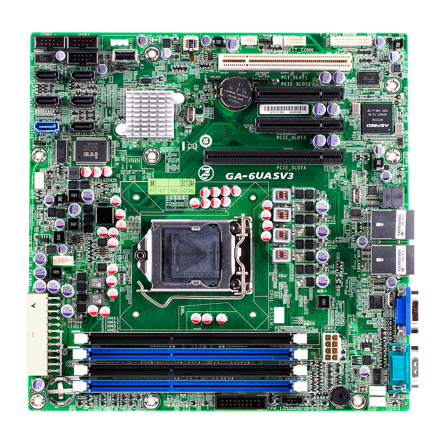
Page 5: Ga-6Uasv3 Motherboard Layout
GA-6UASV3 Motherboard Layout - 5 -... - Page 6 Item Code Description USB_LAN1 USB connectors and LAN connector USB_LAN2 USB connectors and LAN connector VGA1 VGA port COM1 Serial port SYS_FAN3 System fan cable connector CPU_FAN CPU fan cable connector PWR2 8 pin power connector PWR_PMB IPMB connector DIMMB2 DIMM slot (channel B-2 ) DIMMB1 DIMM slot (channel B-1 )
-
Page 7: Chapter 1 Hardware Installation
Chapter 1 Hardware Installation Installation Precautions The motherboard contains numerous delicate electronic circuits and components which can become damaged as a result of electrostatic discharge (ESD). Prior to installation, carefully read the user's manual and follow these procedures: • Prior to installation, do not remove or break motherboard S/N (Serial Number) sticker or warranty sticker provided by your dealer. -
Page 8: Product Specifications
1-2 Product Specifications Support for Intel Xeon E3 series processors in the LGA1155 package Š ® ® L3 cache varies with CPU Š Chipset Intel BD82C202 (Cougar Point) PCH Š ® Memory 4 x 1.5V DDR3 DIMM sockets supporting up to 32 GB of system memory Š... - Page 9 Š AMI BIOS Š Form Factor Micro ATX Form Factor; 9.6 inch x 9.6 inch Š * GIGABYTE reserves the right to make any changes to the product specifications and product-related information without prior notice. - 9 - Hardware Installation...
-
Page 10: Installing The Cpu And Cpu Cooler
Read the following guidelines before you begin to install the CPU: • Make sure that the motherboard supports the CPU. (Go to GIGABYTE's website for the latest CPU support list.) • Always turn off the computer and unplug the power cord from the power outlet before installing the CPU to prevent hardware damage. - Page 11 B. Follow the steps below to correctly install the CPU into the motherboard CPU socket. Before installing the CPU, make sure to turn off the computer and unplug the power cord from the power outlet power plug to prevent any damage to prevent damage to the CPU. Step 1: Step 2: Gently press the CPU socket lever handle down...
-
Page 12: Installing The Cpu Cooler
1-3-2 Installing the CPU Cooler Follow the steps below to correctly install the CPU cooler on the motherboard. (The following procedure uses Intel boxed cooler as the example cooler.) ® Male Push Direction of the Arrow Sign on The Top the Male Push of Female Push Pin... -
Page 13: Installing The Memory
• Make sure that the motherboard supports the memory. It is recommended that memory of the same capacity, brand, speed, and chips be used. (Go to GIGABYTE's website for the latest supported memory speeds and memory modules.) • Always turn off the computer and unplug the power cord from the power outlet before installing the memory to prevent hardware damage. -
Page 14: Installing A Memory
1-4-2 Installing a Memory Before installing a memory module, make sure to turn off the computer and unplug the power cord from the power outlet to prevent damage to the memory module. Be sure to install DDR3 DIMMs on this motherboard. Installation Step: Step 1. -
Page 15: Back Panel Connectors
Back Panel Connectors Serial Port Connects to serial-based mouse or data processing devices. Video Port The video in port allows connect to video in, which can also apply to video loop thru function. RJ-45 LAN Port The Gigabit Ethernet LAN port provides Internet connection at up to 1 Gbps data rate. The following describes the states of the LAN port LEDs. -
Page 16: Internal Connectors
Internal Connectors PWR1 USB2 PWR2 USB_A1 CPU_FAN (CPU Fan) F_PANEL SYS_FAN1 (System Fan) SGPIO SYS_FAN2 (System Fan) HD_LED SYS_FAN3 (System Fan) PWR_IPMB CLR_CMOS SATA0/1/2/3/4/5 MFGJMPR COM2 CLR_PWD USB1 BIOS_RVCR Read the following guidelines before connecting external devices: • First make sure your devices are compliant with the connectors you wish to connect. • Before installing the devices, be sure to turn off the devices and your computer. - Page 17 1/2) PWR1/PWR2 (2x4 12V Power Connector and 2x12 Main Power Connector) With the use of the power connector, the power supply can supply enough stable power to all the com- ponents on the motherboard. Before connecting the power connector, first make sure the power supply is turned off and all devices are properly installed.
- Page 18 3/4/5/6) CPU_FAN/SYS_FAN1/SYS_FAN2/SYS_FAN3 (CPU Fan/System Fan Headers) The motherboard has a 4-pin CPU fan header (FAN1), a 4-pin (FAN4) system fan headers. Most fan headers possess a foolproof insertion design. When connecting a fan cable, be sure to connect it in the correct orientation (the black connector wire is the ground wire).
- Page 19 PORT PORT PORT 8) SATA0/1/2/3/4/5 (SATA 3Gb/s Connectors) The SATA connectors conform to SATA 3Gb/s standard and are compatible with SATA 1.5Gb/s standard. Each SATA connector supports a single SATA device. Pin No. Definition • A RAID 0 or RAID 1 configuration requires at least two hard drives. If more than two hard drives are configured, the total number of hard drives must be an even number.
- Page 20 10/11) USB1/USB2 (USB Headers) The headers conform to USB 2.0/1.1 specification. Each USB header can provide two USB ports via an optional USB bracket. For purchasing the optional USB bracket, please contact the local dealer. Pin No. Definition Power (5V) 10 9 Power (5V) USB DX-...
-
Page 21: Front Panel Header
13) F_PANEL (Front Panel Header) Connect the power switch, reset switch, speaker, chassis intrusion switch/sensor and system status indicator on the chassis to this header according to the pin assignments below. Note the positive and negative pins before connecting the cables. 12 24 Pin No. - Page 22 14) SGPIO (SGPIO Header) SGPIO is stands for Serial General Purpose Input/Output which is a 4-signal (or 4-wire) bus used be- tween a Host Bus Adapter (HBA) and a backplane. Out of the 4 signals, 3 are driven by the HBA and 1 is driven by the backplane.
-
Page 23: Hardware Installation
16) BAT (Battery) The battery provides power to keep the values (such as BIOS configurations, date, and time information) in the CMOS when the computer is turned off. Replace the battery when the battery voltage drops to a low level, or the CMOS values may not be accurate or may be lost. You may clear the CMOS values by removing the battery: 1. - Page 24 18) CLR_CMOS (Clearing CMOS Jumper) Use this jumper to clear the CMOS values (e.g. date information and BIOS configurations) and reset the CMOS values to factory defaults. To clear the CMOS values, place a jumper cap on the two pins to temporarily short the two pins or use a metal object like a screwdriver to touch the two pins for a few seconds.
- Page 25 20) BIOS_RVCR (BIOS Recovery Jumper) 1-2 Close: Normal operation. (Default setting) 2-3 Close: BIOS recovery mode. Hardware Installation - 25 -...
-
Page 26: Chapter 2 Bios Setup
Chapter 2 BIOS Setup BIOS (Basic Input and Output System) records hardware parameters of the system in the NVRM on the motherboard. Its major functions include conducting the Power-On Self-Test (POST) during system startup, saving system parameters and loading operating system, etc. BIOS includes a BIOS Setup program that allows the user to modify basic system configuration settings or to activate certain system features. -
Page 27: Server Management
Main This setup page includes all the items in standard compatible BIOS. Advanced This setup page includes all the items of AMI BIOS special enhanced features. (ex: Automatically configure hard disk parameters.) Security Change, set, or disable supervisor and user password. Configuration supervisor password allows you to restrict access to the system and BIOS Setup. -
Page 28: The Main Menu
The Main Menu Once you enter the BIOS Setup program, the Main Menu (as shown below) appears on the screen. Use arrow keys to move among the items and press <Enter> to accept or enter other sub-menu. Main Menu Help The on-screen description of a highlighted setup option is displayed on the bottom line of the Main Menu. - Page 29 BIOS Version Display version number of the BIOS setup utility. BIOS Build Date Displays the date when the BIOS setup utility was created. Processor Information: CPU Type / CPU Core Frequency / CPU Count Displays the technical specifications for the installed processor. Memory Determines how much total memory is present during the POST.
-
Page 30: Advanced Menu
Advanced Menu The Advanced menu display submenu options for configuring the function of various hardware components. Select a submenu item, then press Enter to access the related submenu screen. - 30 - BIOS Setup... -
Page 31: Processor Configuration
2-2-1 Processor Configuration BIOS Setup - 31 -... -
Page 32: Intel Hyper Threading Technology
Intel Hyper Threading Technology The Intel Hyper Threading Technology allows a single processor to execute two or more separate threads concurrently. When hyper-threading is enabled, multi-threaded software applications can execute their threads, thereby improving performance. Options available: Enabled/Disabled. Default setting is Enabled. Active Processor Cores (Note) Allows you to determine whether to enable all CPU cores. -
Page 33: Hardware Prefetcher
Hardware Prefetcher Select whether to enable the speculative prefetch unit of the processor. Options available: Enabled/Disabled. Default setting is Enabled. Adjacent Cache Line Prefetch When enabled, cache lines are fetched in pairs. When disabled, only the required cache line is fetched. Options available: Enabled/Disabled. -
Page 34: Memory Configuration
2-2-2 Memory Configuration Available Memory Total size of system memory detected during POST. Memory Type Display information of installed memory type. Memory Reset Select whether to delete the historical memory data log. System memory will be retested on the next boot-up. Options available: Yes/No. -
Page 35: Advanced Chipset Configuration
2-2-3 Advanced Chipset Configuration Intel VD-d Technology Enable/Disable Intel VD-d Technology function. Options available: Enabled/Disabled. Default setting is Disabled. Intel TXT Technology Enable/Disable Intel TXT Technology function. Options available: Enabled/Disabled. Default setting is Disabled. Serial Port 1/2 When enabled allows you to configure the serial port settings. When set to Disabled, displays no con- figuration for the serial port. - Page 36 Restore on AC Power Loss Defines the power state to resume to after a sys- tem shutdown that is due to an interruption in AC power. When set to Last State, the system will return to the active power state prior to shutdown. When set to Stay Off, the system remains off after power shutdown.
-
Page 37: Sata Configuration
2-2-4 SATA Configuration SATA Mode Select the on chip SATA type. IDE Mode: When set to IDE, the SATA controller disables its RAID and AHCI functions and runs in the IDE emulation mode. This is not allowed to access RAID setup utility. RAID Mode: When set to RAID, the SATA controllerenables both its RAID and AHCI functions. -
Page 38: Pci Configuration
2-2-5 PCI Configuration Onboard Graphics Controller When enabled, the graphic controller will function normally. Options available: enabled/Disabled. Default setting is Enabled. Primary Graphics Select the primary video device that that the BIOS will use for output. Options available: Add-On/Onboard. Default setting is Add-On. Onboard LAN1/2 I/O ROM Select whether to enable the selected onboard LAN device. -
Page 39: Usb Configuration
2-2-6 USB Configuration USB Controller When enabled, the USB controller will function normally. Options available: Enabled/Disabled. Default setting is Enabled. Legacy USB Support Enables or disables support for legacy USB devices. Options available: Enabled/Disabled. Default setting is Enabled. Port 60/64 Emulation Enable I/O port 60h/64h emulation support. -
Page 40: Console Redirection
2-2-7 Console Redirection Console Redirection (Note) Select whether to enable console redirection. Console redirection enables users to manage the system from a remote location. Options available: Serial Port1/Serial Port2/Disabled. Default setting is Disabled. Terminal Type Select a terminal type to be used for console redirection. Options available: VT100/VT100+/ANSI /VT-UTF8. -
Page 41: Flow Control
Flow Control Flow control can prevent data loss from buffer overflow. When sending data, if the receiving buffers are full, a 'stop' signal can be sent to stop the data flow. Once the buffers are empty, a 'start' signal can be sent to re-start the flow. -
Page 42: Security Menu
Security Menu The Security menu allows you to safeguard and protect the system from unauthorized use by setting up ac- cess passwords. There are two types of passwords that you can set: • Administrator Password Entering this password will allow the user to access and change all settings in the Setup Utility. •... -
Page 43: Server Management Menu
Server Management Menu System Information Displays basic system ID information, as well as BIOS version. Press Enter to access the related sub- menu. BMC LAN Configuration BMC LAN Configuration. Press Enter to access the related submenu. - 43 - BIOS Setup... -
Page 44: System Information
2-4-1 System Information The System Management submenu is a simple display page for basic system ID information, as well as Sys- tem product information. Items on this window are non-configurable. - 44 - BIOS Setup... -
Page 45: Bmc Lan Configuration
2-4-2 BMC LAN Configuration Clear all Event Logs Choose options for erasing Smbios Event Log is done prior to any logging activation during reset. Configuration Source Select to configure LAN channel parameters statically or dynamically (DHCP). Do nothing option willnot modify any BMC network parameters during BIOS phase. Options available: Static/Dynamic/Do Nothing. -
Page 46: Boot Option Menu
Boot Option Menu The Boot menu allows you to set the drive priority during system boot-up. BIOS setup will display an error message if the drive(s) specified is not bootable. By default, the server searches for boot devices in the following secquence: Hard drive. - Page 47 Bootup NumLock Enable or Disable Bootup NumLock function. Options available: On/Off. Default setting is On. POST Error Pause Select whether to pause POST when a boot-up error is detected. Options available: Enabled/Disabled. Default setting is Enabled. - 47 - BIOS Setup...
-
Page 48: Boot Manager
Boot Manager The Boot manager menu allows you to specify the boot-up drive. BIOS setup will display an error message if the drive(s) specified is not bootable. Built-in EFI Shell Press Enter to configure the device as the boot-up drive. IBA GE Slot 00C8 v1365 Press Enter to configure the device as the boot-up drive. -
Page 49: Exit Menu
Exit Menu The Exit menu displays the various options to quit from the BIOS setup. Highlight any of the exit options then press Enter. Save Changes and Exit Saves changes made and close the BIOS setup. Options available: Yes/No. Discard Changes and Exit Discards changes made and close the BIOS setup.
Need help?
Do you have a question about the GA-6UASV3 and is the answer not in the manual?
Questions and answers