Table of Contents
Advertisement
Advertisement
Chapters
Table of Contents

Related Manuals for Asus A88XM-E


Summary of Contents for Asus A88XM-E
- Page 1 A88XM-E...
- Page 2 Product warranty or service will not be extended if: (1) the product is repaired, modified or altered, unless such repair, modification of alteration is authorized in writing by ASUS; or (2) the serial number of the product is defaced or missing.
-
Page 3: Table Of Contents
Contents Safety information ..................iv About this guide ..................iv Package contents ..................vi A88XM-E specifications summary ............vi Chapter 1: Product introduction Before you proceed ..............1-1 Motherboard overview ..............1-2 Accelerated Processing Unit (APU) ........... 1-4 System memory ................1-8 Expansion slots ................ -
Page 4: Safety Information
Safety information Electrical safety • To prevent electrical shock hazard, disconnect the power cable from the electrical outlet before relocating the system. • When adding or removing devices to or from the system, ensure that the power cables for the devices are unplugged before the signal cables are connected. If possible, disconnect all power cables from the existing system before you add a device. -
Page 5: Conventions Used In This Guide
Refer to the following sources for additional information and for product and software updates. ASUS websites The ASUS website provides updated information on ASUS hardware and software products. Refer to the ASUS contact information. Optional documentation Your product package may include optional documentation, such as warranty flyers, that may have been added by your dealer. -
Page 6: Package Contents
DDR3 2400(O.C.)/2133/1866/1600/1333 MHz memory modules Dual-channel memory architecture Supports AMD Memory Profile (AMP) memory • Hyper DIMM support is subject to the physical characteristics of indivudal APUs. • The maximum 32GB memory capacity can be supported with 16GB or above DIMMs. ASUS will update the memory QVL once the DIMMs are available in the market. • Refer to www.asus.com for the latest Memory QVL (Qualified Vendors List). • When you install a total memory of 4GB capacity or more, Windows 32-bit ®... - Page 7 - ASUS AI Charger - ASUS Disk Unlocker - ASUS AI Suite 3 - ASUS Anti Surge - ASUS UEFI BIOS EZ Mode featuring friendly graphics user interface ASUS Quiet Thermal Solution - ASUS Fan Xpert - Stylish Fanless Design Heat-sink solution...
- Page 8 BIOS features 64 Mb Flash ROM, UEFI AMI BIOS, PnP, DMI 2.0, WfM 2.0, SM BIOS 2.7, ACPI 2.0a, Multi-language BIOS, ASUS EZ Flash 2, ASUS CrashFree BIOS 3, My Favorites, Quick Note, Last Modified Log, F12 PrintScreen function, F3 Shortcut functions, and ASUS DRAM SPD (Serial Presence...
-
Page 9: Chapter 1: Product Introduction
The motherboard comes with a standby power LED that lights up to indicate that the system is ON, in sleep mode, or in soft-off mode. This is a reminder that you should shut down the system and unplug the power cable before removing or plugging in any motherboard component. The illustration below shows the location of the onboard LED. SB_PWR A88XM-E Standby Power Powered Off A88XM-E Onboard LED ASUS A88XM-E... -
Page 10: Motherboard Overview
1.2.2 Screw holes Place six screws into the holes indicated by circles to secure the motherboard to the chassis. Do not overtighten the screws! Doing so can damage the motherboard. Place this side towards the rear of the chassis A88XM-E Chapter 1: Product introduction... -
Page 11: Motherboard Layout
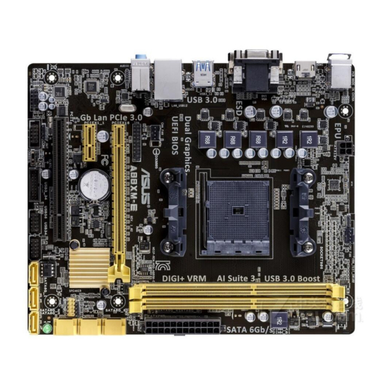
1.2.3 Motherboard layout 18.8cm(7.4in) CPU_FAN KBMS DIGI ATX12V +VRM HDMI USB3_12 LAN_USB12 CHA_FAN AUDIO A88XM-E 8111 PCIEX16 ® Super BATTERY PCIEX1_1 A88X SPEAKER F_PANEL PCI1 64Mb SPDIF_OUT SB_PWR SATA6G_1 BIOS USB3_34 USB56 USB34 SATA6G_2 SATA6G_3 AAFP 15 14 ASUS A88XM-E... -
Page 12: Accelerated Processing Unit (Apu)
9. Standby power LED (SB_PWR) 10. USB 2.0 connectors (10-1 pin USB34, USB56) 1-20 11. USB 3.0 connector (20-1 pin USB3_34) 1-20 12. Clear RTC RAM (2-pin CLRTC) 1-12 13. Serial port connector (10-1 pin COM) 1-19 14. Digital audio connector (4-1 pin SPDIF_OUT) 1-17 15. Front panel audio connector (10-1 pin AAFP) 1-19 Accelerated Processing Unit (APU) This motherboard comes with a FM2+ socket designed for AMD A-series and Athlon™ ® series processors. Ensure that you use an APU designed for the FM2+ socket. The APU fits in only one correct orientation. DO NOT force the APU into the socket to prevent bending the pins and damaging the APU! A88XM-E A88XM-E CPU socket FM2+ Chapter 1: Product introduction... - Page 13 1.3.1 APU installation ASUS A88XM-E...
-
Page 14: Apu Heatsink And Fan Assembly Installation
1.3.2 APU heatsink and fan assembly installation Apply the Thermal Interface Material to the APU heatsink and APU before you install the heatsink and fan if necessary. To install the APU heatsink and fan assembly Chapter 1: Product introduction... - Page 15 To uninstall the APU heatsink and fan assembly ASUS A88XM-E...
-
Page 16: System Memory
1.4.1 Overview This motherboard comes with two Double Data Rate 3 (DDR3) Dual Inline Memory Modules (DIMM) sockets. A DDR3 module has the same physical dimensions as a DDR2 DIMM but is notched differently to prevent installation on a DDR2 DIMM socket. DDR3 modules are developed for better performance with less power consumption. The figure illustrates the location of the DDR3 DIMM sockets: Channel Sockets Channel A DIMM_A1 Channel B DIMM_B1 A88XM-E A88XM-E 240-pin DDR3 DIMM sockets 1.4.2 Memory configurations You may install 1GB, 2GB, 4GB, and 8GB unbuffered non-ECC DDR3 DIMMs into the DIMM sockets. • You may install varying memory sizes in Channel A and Channel B. The system maps the total size of the lower-sized channel for the dual-channel configuration. Any excess memory from the higher-sized channel is then mapped for single-channel operation. • Always install DIMMs with the same CAS latency. For optimal compatibility, we recommend that you install memory modules of the same version or date code (D/C) from the same vendor. Check with the retailer to get the correct memory modules. •... -
Page 17: Installing A Dimm
• The default memory operation frequency is dependent on its Serial Presence Detect (SPD), which is the standard way of accessing information from a memory module. Under the default state, some memory modules for overclocking may operate at a lower frequency than the vendor-marked value. To operate at the vendor-marked or at a higher frequency, refer to section 2.5 Ai Tweaker menu for manual memory frequency adjustment. • For system stability, use a more efficient memory cooling system to support a full memory load (2 DIMMs) or overclocking condition. • Visit the ASUS website at: www.asus.com for the latest QVL. 1.4.3 Installing a DIMM ASUS A88XM-E... -
Page 18: Expansion Slots
To remove a DIMM Expansion slots In the future, you may need to install expansion cards. The following sub-sections describe the slots and the expansion cards that they support. Unplug the power cord before adding or removing expansion cards. Failure to do so may cause you physical injury and damage motherboard components. 1.5.1 Installing an expansion card To install an expansion card: Before installing the expansion card, read the documentation that came with it and make the necessary hardware settings for the card. Remove the system unit cover (if your motherboard is already installed in a chassis). -
Page 19: Pci Slot
– OnChip XHCI controller1 – – shared – – – – – OnChip XHCI controller2 – shared – – – – – – OnChip USB EHCI 1/2/3 – shared – – – – – – OnChip USB OHCI – – shared – – – – – ASUS A88XM-E 1-11... -
Page 20: Jumpers
CMOS, which include system setup information such as system passwords. CLRTC A88XM-E Normal Clear CMOS (Open) (Short) A88XM-E Clear RTC RAM To erase the RTC RAM: Turn OFF the computer and unplug the power cord. Use a metal object such as a screwdriver to short the two pins. Plug the power cord and turn ON the computer. Hold down the <Del> key during the boot process and enter BIOS setup to re- enter data. •... -
Page 21: Connectors
5.1 or 7.1-channel configuration. Audio 2.1, 4.1, 5.1 or 7.1-channel configuration Headset Port 4.1-channel 5.1-channel 7.1-channel 2.1-channel Light Blue (Rear Line In Rear Speaker Out Rear Speaker Out Rear Speaker Out panel) Front Speaker Lime (Rear panel) Line Out Front Speaker Out Front Speaker Out Pink (Rear panel) Mic In Mic In Bass/Center Bass/Center Lime (Front panel) — — — Side Speaker Out ASUS A88XM-E 1-13... - Page 22 To configure a 7.1-channel audio output: Use a chassis with HD audio module in the front panel to support a 7.1-channel audio output. USB 2.0 ports 1 and 2. These two 4-pin Universal Serial Bus (USB) ports are for USB 2.0/1.1 devices. USB 3.0 ports 1 and 2. These two 9-pin Universal Serial Bus (USB) ports are for USB 3.0/2.0 devices. • DO NOT connect a keyboard / mouse to any USB 3.0 port when installing Windows ® operating system. • Due to USB 3.0 controller limitation, USB 3.0 devices can only be used under Windows OS environment and after the USB 3.0 driver installation. ® • USB 3.0 devices can only be used as data storage only. • We strongly recommend that you connect USB 3.0 devices to USB 3.0 ports for faster and better performance for your USB 3.0 devices. DVI-D port. This port is for any DVI-D compatible device. DVI-D can’t be converted to output RGB Signal to CRT and isn’t compatible with DVI-I.
-
Page 23: C Pu And Chassis Fan Connectors (4-Pin Cpu_Fan, And 4-Pin Cha_Fan)
1.7.2 Internal connectors CPU and chassis fan connectors (4-pin CPU_FAN, and 4-pin CHA_FAN) Connect the fan cables to the fan connectors on the motherboard, ensuring that the black wire of each cable matches the ground pin of the connector. CPU_FAN CHA_FAN A88XM-E A88XM-E Fan connectors DO NOT forget to connect the fan cables to the fan connectors. Insufficient air flow inside the system may damage the motherboard components. These are not jumpers! DO NOT place jumper caps on the fan connectors. • The CPU_FAN connector supports a CPU fan of maximum 2A (24W) fan power. • Only the 4-pin CPU fan and 4-pin chassis fan support the ASUS Fan Xpert feature. TPM connector (20-1 pin TPM) This connector supports a Trusted Platform Module (TPM) system, which can securely store keys, digital certificates, passwords, and data. A TPM system also helps enhance... -
Page 24: Atx Power Connectors (24-Pin Eatxpwr, 4-Pin Atx12V)
Power OK -5 Volts PIN 1 +5 Volts +5 Volts PSON# A88XM-E +3 Volts -12 Volts +3 Volts +3 Volts PIN 1 A88XM-E ATX power connectors • We recommend that you use an ATX 12V Specification 2.0-compliant power supply unit (PSU) with a minimum of 300W power rating. This PSU type has 24-pin and 4-pin power plugs. • If you intend to use a PSU with 20-pin and 4-pin power plugs, ensure that the 20-pin power plug can provide at least 15 A on +12 V and that the PSU has a minimum power rating of 300W. The system may become unstable or may not boot up if the power is inadequate. • DO NOT forget to connect the 4-pin ATX +12V power plug. Otherwise, the system will not boot up. -
Page 25: Digital Audio Connector (4-1 Pin Spdif_Out)
RSATA_TXP6 SATA6G_5 RSATA_RXP5 RSATA_RXN5 RSATA_TXN5 RSATA_TXP5 SATA6G_4 RSATA_RXP4 RSATA_RXN4 SATA6G_1 SATA6G_2 SATA6G_3 RSATA_TXN4 RSATA_TXP4 A88XM-E A88XM-E SATA 6.0Gb/s connectors • These connectors are set to AHCI mode by default. If you intend to create a Serial ATA RAID set using these connectors, set the type of the SATA connectors in the BIOS to [RAID]. See section 2.6.2 SATA Configuration for details. • You must install Windows XP Service Pack 3 or later version before using Serial ® ATA hard disk drives. The Serial ATA RAID feature is available only if you are using Windows XP SP3 or later version. ® • When using hot-plug and NCQ, set the type of the SATA connectors in the BIOS to [AHCI]. -
Page 26: Speaker Connector (4-Pin Speaker)
F_PANEL +PWR LED PWR BTN PIN 1 A88XM-E +HDD_LED RESET A88XM-E System panel connector • System power LED (2-pin PWR_LED) This 2-pin connector is for the system power LED. Connect the chassis power LED cable to this connector. The system power LED lights up when you turn on the system power, and blinks when the system is in sleep mode. • Hard disk drive activity LED (2-pin HDD_LED) This 2-pin connector is for the HDD Activity LED. Connect the HDD Activity LED cable... -
Page 27: Serial Port Connector (10-1 Pin Com)
AAFP PIN 1 PIN 1 A88XM-E HD-audio-compliant Legacy AC’97 pin definition compliant definition A88XM-E Front panel audio connector • We recommend that you connect a high-definition front panel audio module to this connector to avail of the motherboard high-definition audio capability. • If you want to connect a high definition front panel audio module to this connector, set the Front Panel Type item in the BIOS to [HD]. See section 2.6.5 Onboard Devices Configuration for details. • The front panel audio I/O module is purchased separately. Serial port connector (10-1 pin COM) This connector is for a serial (COM) port. Connect the serial port module cable to this... -
Page 28: Usb 2.0 Connectors (10-1 Pin Usb34, Usb56)
10. USB 2.0 connectors (10-1 pin USB34, USB56) These connectors are for USB 2.0 ports. Connect the USB module cable to any of these connectors, then install the module to a slot opening at the back of the system chassis. These USB connectors comply with USB 2.0 specification that supports up to 480Mbps connection speed. USB56 USB34 A88XM-E PIN 1 PIN 1 A88XM-E USB2.0 connectors Never connect a 1394 cable to the USB connectors. Doing so will damage the motherboard! The USB 2.0 module is purchased separately. USB 3.0 connector (20-1 pin USB3_34) These connectors allow you to connect a USB 3.0 module for additional USB 3.0 front or rear panel ports. With an installed USB 3.0 module, you can enjoy all the benefits of USB 3.0 including faster data transfer speeds of up to 5Gbps, faster charging time for USB-chargeable devices, optimized power efficiency and backward compatibility with USB 2.0. USB3_34 A88XM-E A88XM-E USB3.0 connector You can connect the ASUS front panel USB 3.0 bracket to this connector to obtain the front panel USB 3.0 solution. 1-20 Chapter 1: Product introduction... -
Page 29: Software Support
® Windows 8.1 before installing the drivers for better compatibility and system stability. ® 1.8.2 Support DVD information The Support DVD that comes with the motherboard package contains the drivers, software applications, and utilities that you can install to avail all motherboard features. The contents of the Support DVD are subject to change at any time without notice. Visit the ASUS website at www.asus.com for updates. To run the Support DVD Place the Support DVD into the optical drive. If Autorun is enabled in your computer, the DVD automatically displays the Specials screen. Click Drivers, Utilities, Make Disk, Manual, and Contact tabs to display their respective menus. The following screen is for reference only. Click an icon to display Support DVD/motherboard information Click an item to install If Autorun is NOT enabled on your computer, browse the contents of the Support DVD to locate the file ASSETUP.EXE from the BIN folder. Double-click the ASSETUP.EXE to run... - Page 30 1-22 Chapter 1: Product introduction...
-
Page 31: Chapter 2: Bios Information
Managing and updating your BIOS Save a copy of the original motherboard BIOS file to a USB flash disk in case you need to restore the BIOS in the future. Copy the original motherboard BIOS using the ASUS Update utility. -
Page 32: Asus Ez Flash
2.1.2 ASUS EZ Flash 2 The ASUS EZ Flash 2 feature allows you to update the BIOS without using an OS‑based utility. Before you start using this utility, download the latest BIOS file from the ASUS website at www.asus.com. To update the BIOS using EZ Flash 2: Insert the USB flash disk that contains the latest BIOS file to the USB port. -
Page 33: Asus Crashfree Bios 3 Utility
2.1.3 ASUS CrashFree BIOS 3 utility The ASUS CrashFree BIOS 3 is an auto recovery tool that allows you to restore the BIOS file when it fails or gets corrupted during the updating process. You can restore a corrupted BIOS file using the motherboard support DVD or a USB flash drive that contains the updated BIOS file. - Page 34 Insert the DOS‑bootable USB flash drive with the latest BIOS file and BIOS Updater to your computer’s USB port. Boot your computer. When the ASUS Logo appears, press <F8> to show the BIOS Boot Device Select Menu. Select the optical drive as the boot device. The DOS screen appears.
- Page 35 Ensure to load the BIOS default settings to ensure system compatibility and stability. Select the Load Optimized Defaults item under the Exit menu. Refer to section 2.10 Exit menu for details. • Ensure to connect all SATA hard disk drives after updating the BIOS file if you have disconnected them. ASUS A88XM-E...
-
Page 36: Bios Setup Program
BIOS setup program Use the BIOS Setup program to update the BIOS or configure its parameters. The BIOS screens include navigation keys and brief online help to guide you in using the BIOS Setup program. Entering BIOS Setup at startup To enter BIOS Setup at startup: •... -
Page 37: Advanced Mode
The Advanced Mode provides advanced options for experienced end‑users to configure the BIOS settings. The figure below shows an example of the Advanced Mode. Refer to the following sections for the detailed configurations. To access the EZ Mode, click Exit, then select ASUS EZ Mode or press F7. ASUS A88XM-E 2‑7... -
Page 38: Menu Bar
Back button Menu items Menu bar Configuration fields General help Last modified Navigation keys Pop-up window settings Quick Scroll bar note Menu bar The menu bar on top of the screen has the following main items: My Favorites For saving the frequently‑used system settings and configuration Main For changing the basic system configuration Ai Tweaker... -
Page 39: My Favorites
This button allows you to enter notes of the activities that you have done in BIOS. Last Modified button This button shows the items that you last modified and saved in BIOS Setup. My Favorites MyFavorites is your personal space where you can easily save and access your favorite BIOS items. ASUS A88XM-E... -
Page 40: Main Menu
Adding items to My Favorites To add frequently‑used BIOS items to My Favorites: Use the arrow keys to select an item that you want to add. When using a mouse, hover the pointer to the item. Press <F4> on your keyboard or right‑click on your mouse to add the item to My Favorites page. -
Page 41: Administrator Password
To clear the user password, follow the same steps as in changing a user password, but press <Enter> when prompted to create/confirm the password. After you clear the password, the User Password item on top of the screen shows Not Installed. ASUS A88XM-E 2-11... -
Page 42: Ai Tweaker Menu
Ai Tweaker menu The Ai Tweaker menu items allow you to configure overclocking‑related items. Be cautious when changing the settings of the Ai Tweaker menu items. Incorrect field values can cause the system to malfunction. The configuration options for this section vary depending on the CPU and DIMM model you installed on the motherboard. - Page 43 This item appears only when The EPU Power Saving Mode is set to [Enabled] and allows you to set power saving mode. Configuration options: [Auto] [Light Power Saving Mode] [Medium Power Saving Mode] [Max Power Saving Mode] ASUS A88XM-E 2‑13...
-
Page 44: Dram Timing Control
2.5.6 DRAM Timing Control The sub‑items in this menu allow you to set the DRAM timing control features. Use the <+> and <‑> keys to adjust the value. To restore the default setting, type [auto] using the keyboard and press <Enter>. Changing the values in this menu may cause the system to become unstable! If this happens, revert to the default settings. - Page 45 Reducing phase number under light system loading to increase VRM efficiency. [Standard] Proceeds phase control depending on the CPU loading. [Optimized] Loads the ASUS optimized phase tuning profile. [Extreme] Proceeds the full phase mode. [Manual Adjustment] Allows manual adjustment.
-
Page 46: Advanced Menu
Manual Adjustment [Fast] This item appears only when you set the previous item to [Manual Adjustment]. Select [Ultra Fast] for a faster response. The reaction time will be longer when [Regular] is selected. Configuration options: [Ultra Fast] [Fast] [Medium] [Regular] CPU Voltage Frequency [300] Switching frequency will affect the VRM transient response and component thermal. -
Page 47: Cpu Configuration
While entering Setup, the BIOS automatically detects the presence of SATA devices. The SATA Port items show Not Present if no SATA device is installed to the corresponding SATA port. OnChip SATA Channel [Enabled] Enables or disables onboard channel SATA port. Configuration options: [Disabled] [Enabled] ASUS A88XM-E 2‑17... -
Page 48: Usb Configuration
OnChip SATA Type [AHCI] Allows you to set the SATA configuration. [IDE] Set to [IDE] when you want to use the Serial ATA hard disk drives as Parallel ATA physical storage devices. [RAID] Set to [RAID] when you want to create a RAID configuration from the SATA hard disk drives. -
Page 49: Onboard Devices Configuration
[Auto] [64M] [128M] [256M] [512M] [1G] [2G] 2.6.5 Onboard Devices Configuration HD Audio Device [Enabled] [Enabled] Enables the High Definition Audio Controller. [Disabled] Disables the controller. The following two items appear only when you set the HD Audio Device item to [Enabled]. ASUS A88XM-E 2-19... -
Page 50: Serial Port Configuration
Front Panel Type [HD] Allows you to set the front panel audio connector (AAFP) mode to legacy AC’97 or high‑ definition audio depending on the audio standard that the front panel audio module supports. [HD] Sets the front panel audio connector (AAFP) mode to high definition audio. [AC97] Sets the front panel audio connector (AAFP) mode to legacy AC’97. -
Page 51: Network Stack
[Disabled] [Enabled] The following two items appear only when you set the previous item to [Enabled]. Ipv4 PXE Support [Enabled] This item allows user to disable or enable the Ipv4 PXE Boot support. Configuration options: [Disabled] [Enable] ASUS A88XM-E 2-21... -
Page 52: Monitor Menu
Ipv6 PXE Support [Enabled] This item allows user to disable or enable the Ipv6 PXE Boot support. Configuration options: [Disabled] [Enabled] Monitor menu The Monitor menu displays the system temperature/power status, and allows you to change the fan settings. Scroll down to display the following items: 2-22 Chapter 2: BIOS information... - Page 53 Use the <+> and <‑> keys to adjust the minimum CPU fan duty cycle. The values range from 20% to 100%. When the CPU temperature is under the lower limit, the CPU fan will operate at the minimum duty cycle. ASUS A88XM-E 2‑23...
- Page 54 2.7.4 Chassis Q-Fan Control [Enabled] [Disabled] Disables the Chassis1 Q‑Fan control feature. [Enabled] Enables the Chassis1 Q‑Fan control feature. Fan Speed Low Limit [600 RPM] This item appears only when you enable the Chassis1 Q‑Fan Control feature and allows you to disable or set the chassis1 fan warning speed. Configuration options: [Ignore] [200RPM] [300 RPM] [400 RPM] [500 RPM] [600 RPM] Q-Fan Profile [Standard] This item appears only when you enable the Chassis1 Q‑Fan Control feature and...
-
Page 55: Boot Menu
Boot menu The Boot menu items allow you to change the system boot options. Scroll down to display the following items: ASUS A88XM-E 2-25... - Page 56 2.8.1 Fast Boot [Enabled] [Enabled] Select to accelerate the boot speed. [Disabled] Select to go back to normal boot. The following four items appear when you set Fast Boot to [Enabled]. SATA Support [All Devices] [All Devices] All devices connected to SATA ports will be available during POST.
-
Page 57: Compatibility Support Module
Sets EZ Mode as the default screen for entering the BIOS setup program. 2.8.8 CSM (Compatibility Support Module) Allows you to configure the CSM (Compatibility Support Module) items to fully support the various VGA, bootable devices and add‑on devices for better compatibility. ASUS A88XM-E 2‑27... -
Page 58: Secure Boot
Launch CSM [Enabled] [Auto] The system automatically detects the bootable devices and the add‑on devices. [Enabled] For better compatibility, enable the CSM to fully support the non‑UEFI driver add‑on devices or the Windows UEFI mode. ® [Disabled] Disable the CSM to fully support the Windows Security Update and ®... -
Page 59: Key Management
The db (Authorized Signature database) lists the signers or images of UEFI applications, operating system loaders, and UEFI drivers that you can load on the single computer. Delete the db Allows you to delete the db file from your system. Configuration options: [Yes] [No] ASUS A88XM-E 2-29... -
Page 60: Boot Option Priorities
• To select the boot device during system startup, press <F8> when ASUS Logo appears. • To access Windows OS in Safe Mode, press <F8> after POST. -
Page 61: Tools Menu
<Enter> to display the submenu. 2.9.1 ASUS EZ Flash 2 Utility Allows you to run ASUS EZ Flash 2. Press [Enter] to launch the ASUS EZ Flash 2 screen. For more details, see section 2.1.2 ASUS EZ Flash 2. 2.9.2... -
Page 62: Exit Menu
This option allows you to exit the Setup program without saving your changes. When you select this option or if you press <Esc>, a confirmation window appears. Select Yes to discard changes and exit. ASUS EZ Mode This option allows you to enter the EZ Mode screen. Launch EFI Shell from filesystem device This option allows you to attempt to launch the UEFI Shell application (shellx64.efi) from one... -
Page 63: Appendices
Cet appareil est conforme aux normes CNR exemptes de licence d’Industrie Canada. Le fonctionnement est soumis aux deux conditions suivantes : (1) cet appareil ne doit pas provoquer d’interférences et (2) cet appareil doit accepter toute interférence, y compris celles susceptibles de provoquer un fonctionnement non souhaité de l’appareil. A88XM-E... -
Page 64: Canadian Department Of Communications Statement
ASUS Recycling/Takeback Services ASUS recycling and takeback programs come from our commitment to the highest standards for protecting our environment. We believe in providing solutions for you to be able to responsibly recycle our products, batteries, other components as well as the packaging materials. -
Page 65: Asus Contact Information
+1-510-739-3777 +1-510-608-4555 Web site http://www.asus.com/us/ Technical Support Support fax +1-812-284-0883 General support +1-812-282-2787 Online support http://www.service.asus.com/ ASUS COMPUTER GmbH (Germany and Austria) Address Harkort Str. 21-23, D-40880 Ratingen, Germany +49-2102-959931 Web site http://www.asus.com/de Online contact http://eu-rma.asus.com/sales Technical Support Telephone +49-2102-5789555... - Page 66 Appendices...
Need help?
Do you have a question about the A88XM-E and is the answer not in the manual?
Questions and answers