Table of Contents
Advertisement
Advertisement
Table of Contents

Related Manuals for Asus A8N5X


Summary of Contents for Asus A8N5X
- Page 1 A8N5X...
- Page 2 Product warranty or service will not be extended if: (1) the product is repaired, modified or altered, unless such repair, modification of alteration is authorized in writing by ASUS; or (2) the serial number of the product is defaced or missing.
-
Page 3: Table Of Contents
How this guide is organized ............ ix Where to find more information ..........ix Conventions used in this guide ..........x Typography ..................x A8N5X specifications summary ............xi Chapter 1: Product introduction Chapter 1: Product introduction Chapter 1: Product introduction... - Page 4 2.1.2 Updating the BIOS ..........2-3 2.1.3 Saving the current BIOS file ........2-5 2.1.4 ASUS CrashFree BIOS 2 utility ........ 2-6 2.1.5 ASUS EZ Flash utility ..........2-8 2.1.6 ASUS Update utility ..........2-9 BIOS setup program ............2-12 2.2.1...
- Page 5 3.2.2 Drivers menu ............3-3 3.2.3 Utilities menu ............3-4 3.2.4 Manuals menu ............3-6 3.2.5 ASUS Contact information ........3-7 3.2.6 Other information ........... 3-7 Software information ............3-9 3.3.1 ASUS MyLogo2™ ............ 3-9 3.3.2 AI NET 2 ............... 3-11 Using the Virtual Cable Tester™...
- Page 6 Contents RAID configurations ............3-21 3.4.1 Installing hard disks ..........3-22 3.4.2 NVIDIA® RAID configurations ....... 3-23 Creating a RAID driver disk ..........3-30 Cool ‘n’ Quiet!™ Technology ..........3-31 3.6.1 Enabling Cool ‘n’ Quiet!™ Technology ....3-31 3.6.2 Launching the Cool ‘n’ Quiet!™ software ....3-32 v i v i v i v i v i...
-
Page 7: Notices
Notices Federal Communications Commission Statement Federal Communications Commission Statement Federal Communications Commission Statement Federal Communications Commission Statement Federal Communications Commission Statement This device complies with Part 15 of the FCC Rules. Operation is subject to the following two conditions: • This device may not cause harmful interference, and •... -
Page 8: Safety Information
Safety information Electrical safety Electrical safety Electrical safety Electrical safety Electrical safety • To prevent electrical shock hazard, disconnect the power cable from the electrical outlet before relocating the system. • When adding or removing devices to or from the system, ensure that the power cables for the devices are unplugged before the signal cables are connected. -
Page 9: About This Guide
A S U S w e b s i t e s A S U S w e b s i t e s The ASUS website provides updated information on ASUS hardware and software products. Refer to the ASUS contact information. -
Page 10: Conventions Used In This Guide
Conventions used in this guide Conventions used in this guide Conventions used in this guide Conventions used in this guide Conventions used in this guide To make sure that you perform certain tasks properly, take note of the following symbols used throughout this manual. D A N G E R / W A R N I N G : D A N G E R / W A R N I N G : D A N G E R / W A R N I N G : Information to prevent injury to yourself... -
Page 11: A8N5X Specifications Summary
O v e r c l o c k i n g O v e r c l o c k i n g AI NOS™ (Non-Delay Overclocking System) ASUS AI Overclocking (Intelligent CPU frequency tuner) ASUS PEG Link Fixed PCI Express/PCI/SATA frequencies ASUS C.P.R. - Page 12 A8N5X specifications summary 1 x Floppy disk drive connector I n t e r n a l I n t e r n a l I n t e r n a l I n t e r n a l...
- Page 13 A8N5X specifications summary F o r m F a c t o r F o r m F a c t o r F o r m F a c t o r F o r m F a c t o r F o r m F a c t o r ATX form factor: 12 in x 9.6 in (30.5 cm x 24.4 cm)
- Page 14 x i v x i v x i v x i v x i v...
- Page 15 This chapter describes the motherboard features and the new technologies it supports. Product introduction A S U S A 8 N 5 X A S U S A 8 N 5 X A S U S A 8 N 5 X 1 - 1 1 - 1 1 - 1...
-
Page 16: Welcome
A 8 N 5 X m o t h e r b o a r d ! The motherboard delivers a host of new features and latest technologies, making it another standout in the long line of ASUS quality motherboards! Before you start installing the motherboard, and hardware devices on it, check the items in your package with the list below. -
Page 17: Special Features
Special features 1.3.1 1.3.1 1.3.1 Product highlights Product highlights Product highlights 1.3.1 1.3.1 Product highlights Product highlights AMD Dual-Core Architecture AMD Dual-Core Architecture AMD Dual-Core Architecture AMD Dual-Core Architecture AMD Dual-Core Architecture The motherboard supports AMD dual-core processors containing two physical CPU cores with discrete L2 cache structure for each core to meet demands for more powerful computing. - Page 18 Dual Channel DDR memory support Dual Channel DDR memory support Dual Channel DDR memory support Dual Channel DDR memory support Dual Channel DDR memory support Employing the Double Data Rate (DDR) memory technology, the motherboard supports up to 4GB of system memory using DDR400/333/ 266 DIMMs.
-
Page 19: Asus Proactive Features
AI NOS™ (Non-Delay Overclocking System) AI NOS™ (Non-Delay Overclocking System) AI NOS™ (Non-Delay Overclocking System) ASUS Non-delay Overclocking System™ (NOS) is a technology that auto-detects the CPU loading and dynamically overclocks the CPU speed only when needed. See page 2-28 for details. -
Page 20: Innovative Asus Features
ASUS Instant Lite ASUS Instant Lite This unique feature allows you to playback audio files even without booting the system to Windows. Just press the ASUS Instant Music Lite special function keys and enjoy the music! See pages 2-31. 1 - 6... -
Page 21: Before You Proceed
SB_PWR A8N5X ® Standby Powered A8N5X Onboard LED Power A S U S A 8 N 5 X A S U S A 8 N 5 X A S U S A 8 N 5 X 1 - 7... -
Page 22: Motherboard Overview
A8N5X 1 - 8... -
Page 23: Motherboard Layout
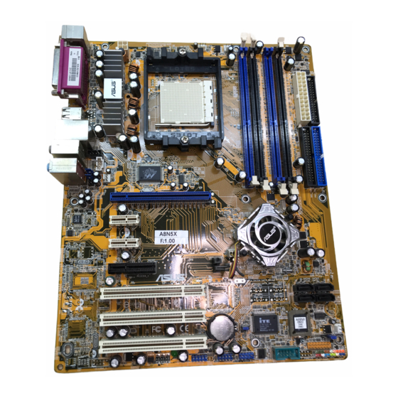
Top:Rear Speaker Out Center: Side Speaker Out Below: Center/Subwoofer Marvell Top:Line In 88E1111 Center:Line Out PWR_FAN Bottom:Mic In FP_AUDIO PCIEX16_1 ACL850 PCIEX1_1 A8N5X nForce4 PCIEX1_2 CHIP_FAN PCIEX4_1 ® SATA4 SATA3 PCI1 SATA2 SATA1 PCI2 Super CR2032 3V CHA1_FAN Lithium Cell... -
Page 24: Central Processing Unit (Cpu)
Locate the CPU socket on the motherboard. A8N5X ® A8N5X CPU Socket 939 Before installing the CPU, make sure that the socket box is facing towards you and the load lever is on your left. Unlock the socket by pressing the lever sideways, then lift it up to a 90°-100°... -
Page 25: Installing The Heatsink And Fan
Position the CPU above the socket such that the CPU corner with the gold triangle matches the socket corner with a small triangle. Carefully insert the CPU into the socket until it fits in place. The CPU fits only in one correct orientation. DO NOT force the CPU into the socket to prevent bending the pins and damaging the CPU! When the CPU is in place, push down the socket lever to secure... - Page 26 ® Hardware monitoring error can occur if you fail to plug this connector. A8N5X CPU fan connector 1 - 1 2 1 - 1 2 1 - 1 2 C h a p t e r 1 : P r o d u c t i n t r o d u c t i o n...
-
Page 27: System Memory
Inline Memory Modules (DIMM) sockets. The following figure illustrates the location of the sockets: A8N5X ® A8N5X 184-pin DDR DIMM sockets C h a n n e l C h a n n e l S o c k e t s... -
Page 28: Memory Configuration
C C C C C - support for 4 modules inserted into the blue and black slots as two pairs of Dual-channel memory configuration. Visit the ASUS website (www.asus.com) for the latest DDR 400 Qualified Vendors List. 1 - 1 4... -
Page 29: Installing A Dimm
1.7.3 1.7.3 1.7.3 Installing a DIMM Installing a DIMM Installing a DIMM 1.7.3 1.7.3 Installing a DIMM Installing a DIMM Make sure to unplug the power supply before adding or removing DIMMs or other system components. Failure to do so may cause severe damage to both the motherboard and the components. -
Page 30: Expansion Slots
Expansion slots In the future, you may need to install expansion cards. The following sub-sections describe the slots and the expansion cards that they support. Make sure to unplug the power cord before adding or removing expansion cards. Failure to do so may cause you physical injury and damage motherboard components. -
Page 31: Interrupt Assignments
1.8.3 1.8.3 1.8.3 Interrupt assignments Interrupt assignments Interrupt assignments 1.8.3 1.8.3 Interrupt assignments Interrupt assignments Standard interrupt assignments Standard interrupt assignments Standard interrupt assignments Standard interrupt assignments Standard interrupt assignments I R Q I R Q I R Q I R Q I R Q P r i o r i t y P r i o r i t y... -
Page 32: Pci Express X16 Slot
This motherboard provides a PCI Express x4 slot that can support PCI Express x1, x4, x8, or x16 cards. This ASUS proprietary slot allows you to use additional PCI Express cards (e.g. graphics card) for twice the speed of a PCI Express x1 slot. -
Page 33: Jumpers
Normal Clear CMOS (Default) A8N5X Clear RTC RAM You do not need to clear the RTC when the system hangs due to overclocking. For system failure due to overclocking, use the C.P.R. (CPU Parameter Recall) feature. Shut down and reboot the system so the BIOS can automatically reset parameter settings to default values. -
Page 34: 1.10 Connectors
1.10 Connectors 1.10.1 1.10.1 1.10.1 Rear panel connectors Rear panel connectors Rear panel connectors Rear panel connectors 1.10.1 1.10.1 Rear panel connectors 1 . 1 . P S / 2 m o u s e p o r t ( g r e e n ) . P S / 2 m o u s e p o r t ( g r e e n ) . - Page 35 Refer to the audio configuration table below for the function of the audio ports in 2, 4, 6, or 8-channel configuration. Audio 2, 4, 6, or 8-channel configuration Audio 2, 4, 6, or 8-channel configuration Audio 2, 4, 6, or 8-channel configuration Audio 2, 4, 6, or 8-channel configuration Audio 2, 4, 6, or 8-channel configuration P o r t...
-
Page 36: Internal Connectors
® PIN 1 A8N5X Floppy disk drive connector 2 . 2 . I D E c o n n e c t o r s ( 4 0 - 1 p i n P R I _ I D E , S E C _ I D E ) - Page 37 SATA3 A8N5X ® SATA2 SATA1 A8N5X SATA connectors A S U S A 8 N 5 X A S U S A 8 N 5 X A S U S A 8 N 5 X 1 - 2 3 1 - 2 3...
- Page 38 These are not jumpers! DO NOT place jumper caps on the fan connectors! • The ASUS Q-Fan function is supported using the CPU Fan (CPU_FAN) and Chassis Fan 1 (CHA1_FAN) connectors only. • The chipset fan is synchronized with the CPU fan.
- Page 39 A8N5X ® A8N5X COM port connector 6 . 6 . U S B c o n n e c t o r s ( 1 0 - 1 p i n U S B 5 6 , U S B 7 8 , U S B 9 1 0 )
- Page 40 +5 Volts +5V Standby +5 Volts +12 Volts +5 Volts +12 Volts A8N5X ATX power connectors Ground +3 Volts 1 - 2 6 1 - 2 6 1 - 2 6 C h a p t e r 1 : P r o d u c t i n t r o d u c t i o n...
- Page 41 Ground Left Audio Channel A8N5X ® A8N5X Internal audio connectors The function of these connectors are disabled under 8-channel mode. 1 0 . 1 0 . 1 0 . G A M E / M I D I p o r t c o n n e c t o r ( 1 6 - 1 p i n G A M E )
- Page 42 MICPWR AGND MIC2 ® A8N5X Front panel audio connector 1 - 2 8 1 - 2 8 1 - 2 8 C h a p t e r 1 : P r o d u c t i n t r o d u c t i o n...
-
Page 43: System Panel Connector
IDE_LED PWRSW Requires an ATX power supply. A8N5X System panel connector The sytem panel connector is color-coded for easy connection. Refer to the connector description below for details. S y s t e m p o w e r L E D ( G r e e n 3 - p i n P L E D ) S y s t e m p o w e r L E D ( G r e e n 3 - p i n P L E D ) •... - Page 44 1 - 3 0 1 - 3 0 1 - 3 0 C h a p t e r 1 : P r o d u c t i n t r o d u c t i o n C h a p t e r 1 : P r o d u c t i n t r o d u c t i o n C h a p t e r 1 : P r o d u c t i n t r o d u c t i o n 1 - 3 0...
- Page 45 This chapter tells how to change the system settings through the BIOS Setup menus. Detailed descriptions of the BIOS parameters are also provided. BIOS setup A S U S A 8 N 5 X A S U S A 8 N 5 X A S U S A 8 N 5 X 2 - 1 2 - 1...
-
Page 46: Managing And Updating Your Bios
Save a copy of the original motherboard BIOS file to a bootable floppy disk in case you need to restore the BIOS in the future. Copy the original motherboard BIOS using the ASUS Update or AwardBIOS Flash utilities. 2.1.1 2.1.1 2.1.1... -
Page 47: Updating The Bios
AwardBIOS Flash Utility. Follow these instructions to update the BIOS using this utility. 1. Download the latest BIOS file from the ASUS web site. Rename the file A 8 N 5 X . B I N A 8 N 5 X . B I N to A 8 N 5 X . - Page 48 Type the BIOS file name AwardBIOS Flash Utility for ASUS V1.01 in the F i l e N a m e t o F i l e N a m e t o F i l e N a m e t o...
-
Page 49: Saving The Current Bios File
Make sure that the floppy disk has enough disk space to save the file. To save the current BIOS file using the AwardBIOS Flash Utility: Follow steps 1 to 6 of AwardBIOS Flash Utility for ASUS V1.01 the previous section. (C) Phoenix Technologies Ltd. All Rights Reserved... -
Page 50: Asus Crashfree Bios 2 Utility
ASUS CrashFree BIOS 2 utility ASUS CrashFree BIOS 2 utility The ASUS CrashFree BIOS 2 is an auto recovery tool that allows you to restore the BIOS file when it fails or gets corrupted during the updating process. You can update a corrupted BIOS file using the motherboard support CD or the floppy disk that contains the updated BIOS file. - Page 51 Restart the system after the utility completes the updating process. The recovered BIOS may not be the latest BIOS version for this motherboard. Visit the ASUS website (www.asus.com) to download the latest BIOS file. A S U S A 8 N 5 X...
-
Page 52: Asus Ez Flash Utility
ASUS EZ Flash utility ASUS EZ Flash utility The ASUS EZ Flash feature allows you to update the BIOS without having to go through the long process of booting from a floppy disk and using a DOS-based utility. The EZ Flash utility is built-in the BIOS chip so it is accessible by pressing <Alt>... -
Page 53: Asus Update Utility
2.1.6 2.1.6 ASUS Update utility ASUS Update utility ASUS Update utility The ASUS Update is a utility that allows you to manage, save, and update the motherboard BIOS in Windows ® environment. The ASUS Update utility allows you to: • Save the current BIOS file •... - Page 54 Updating the BIOS through the Internet Updating the BIOS through the Internet Updating the BIOS through the Internet To update the BIOS through the Internet: Launch the ASUS Update utility from the Windows ® desktop by clicking S t a r t...
- Page 55 A S U S U p d a t e > A S U S U p d a t e A S U S U p d a t e. The ASUS Update main window appears. A S U S U p d a t e...
-
Page 56: Bios Setup Program
The BIOS setup screens shown in this section are for reference purposes only, and may not exactly match what you see on your screen. • Visit the ASUS website (www.asus.com) to download the latest BIOS file for this motherboard and . 2 - 1 2 2 - 1 2... -
Page 57: Bios Menu Screen
• Visit the ASUS website (www.asus.com) to download the latest BIOS information. A S U S A 8 N 5 X A S U S A 8 N 5 X... -
Page 58: Legend Bar
2.2.3 2.2.3 2.2.3 Legend bar Legend bar Legend bar 2.2.3 2.2.3 Legend bar Legend bar At the bottom of the Setup screen is a legend bar. The keys in the legend bar allow you to navigate through the various setup menus. The following table lists the keys found in the legend bar with their corresponding functions. -
Page 59: General Help
Primary IDE Master [ST321122A] diskette drive A. Disabled ..[ ] Primary IDE Slave [ASUS CDS520/A] 360K , 5.25 in..[ ] Secondary IDE Master [None] 1.2M , 5.25 in..[ ] Secondary IDE Slave [None] 720K , 3.5 in. -
Page 60: Main Menu
Item Specific Help Legacy Diskette A: [1.44M, 3.5 in.] Change the day, month, year and century. Primary IDE Master [ST321122A] Primary IDE Slave [ASUS CDS520/A] Secondary IDE Master [None] Secondary IDE Slave [None] First SATA Master [None] Second SATA Slave... -
Page 61: Primary And Secondary Ide Master/Slave
2.3.5 2.3.5 Primary and Secondary IDE Master/Slave Primary and Secondary IDE Master/Slave 2.3.5 2.3.5 2.3.5 Primary and Secondary IDE Master/Slave Primary and Secondary IDE Master/Slave Primary and Secondary IDE Master/Slave While entering Setup, the BIOS automatically detects the presence of IDE devices. - Page 62 Access Mode [Auto] Access Mode [Auto] Access Mode [Auto] Access Mode [Auto] Access Mode [Auto] The default [Auto] allows automatic detection of an IDE hard disk drive. Select [CHS] for this item if you set the IDE Primary Master/Slave to [Manual].
-
Page 63: First, Second, Third, Fourth Sata Master
2.3.6 2.3.6 2.3.6 2.3.6 2.3.6 First, Second, Third, Fourth SATA Master First, Second, Third, Fourth SATA Master First, Second, Third, Fourth SATA Master First, Second, Third, Fourth SATA Master First, Second, Third, Fourth SATA Master While entering Setup, the BIOS automatically detects the presence of Serial ATA devices. -
Page 64: Hdd Smart Monitoring
H e a d H e a d H e a d H e a d H e a d Shows the number of the hard disk read/write heads. This item is not configurable. Precomp Precomp Precomp Precomp Precomp Shows the number of precomp per track. This item is not configurable. Landing Zone Landing Zone Landing Zone... -
Page 65: Advanced Menu
Advanced menu The Advanced menu items allow you to change the settings for the CPU and other system devices. Take caution when changing the settings of the Advanced menu items. Incorrect field values can cause the system to malfunction. Phoenix-Award BIOS CMOS Setup Utility Main Advanced Power... - Page 66 Max Memclock (MHz) [Auto] Sets the maximum operating memory clock. Configuration options: [Auto] [DDR200] [DDR266] [DDR333] [DDR400] [DDR400] [DDR433] [DDR466] [DDR500] [DDR533] [DDR550] [DDR600] 1T/2T Memory Timing [Auto] Sets the memory timing. Configuration options: [Auto] [1T] [2T] CAS# latency (Tcl) [Auto] Sets the CAS# latency.
-
Page 67: Pcipnp
2.4.2 2.4.2 2.4.2 PCIPnP PCIPnP PCIPnP 2.4.2 2.4.2 PCIPnP PCIPnP Phoenix-Award BIOS CMOS Setup Utility Advanced Frequency/Voltage control Select Menu Plug & Play O/S [No] Item Specific Help Init Display First [PCI Slot] Resources Controlled By [Auto] x IRQ Resources PCI/VGA Palette Snoop [Disabled] Plug &... -
Page 68: Onboard Devices Configuration
PCI/VGA Palette Snoop [Disabled] PCI/VGA Palette Snoop [Disabled] PCI/VGA Palette Snoop [Disabled] PCI/VGA Palette Snoop [Disabled] PCI/VGA Palette Snoop [Disabled] When set to [Enabled], the pallete snooping feature informs the PCI devices that an ISA graphics device is installed in the system so that the latter can function correctly. - Page 69 IDE DMA transfer access [Enabled] IDE DMA transfer access [Enabled] IDE DMA transfer access [Enabled] IDE DMA transfer access [Enabled] IDE DMA transfer access [Enabled] Allows you to enable or disable the IDE DMA transfer access. Configuration options: [Disabled] [Enabled] Serial Port 1, 2 [Enabled] Serial Port 1, 2 [Enabled] Serial Port 1, 2 [Enabled]...
- Page 70 IDE Primary, Secondary Master/Slave RAID [Disabled] IDE Primary, Secondary Master/Slave RAID [Disabled] IDE Primary, Secondary Master/Slave RAID [Disabled] IDE Primary, Secondary Master/Slave RAID [Disabled] IDE Primary, Secondary Master/Slave RAID [Disabled] Enables or disables the RAID function of the primary or secondary master or slave IDE.
- Page 71 Serial Port1 Address [3F8/IRQ4] Serial Port1 Address [3F8/IRQ4] Serial Port1 Address [3F8/IRQ4] Serial Port1 Address [3F8/IRQ4] Serial Port1 Address [3F8/IRQ4] Allows you to select the Serial Port1 base address. Configuration options: [Disabled] [3F8/IRQ4] [3E8/IRQ4] [2E8/IRQ3] Parallel Port Address [378/IRQ7] Parallel Port Address [378/IRQ7] Parallel Port Address [378/IRQ7] Parallel Port Address [378/IRQ7] Parallel Port Address [378/IRQ7]...
-
Page 72: Jumperfree Configuration
A I N . O . S . A I N . O . S . A I N . O . S . The ASUS AI Non-delay Overclocking System feature intelligently determines the system load and automatically boost the performance for the most demanding tasks. - Page 73 PCI Express Clock [100MHz] PCI Express Clock [100MHz] PCI Express Clock [100MHz] PCI Express Clock [100MHz] PCI Express Clock [100MHz] Allows you to set the PCI Express clock. Key-in a decimal value between 100-200 MHz. Configuration options: [100Mhz] [101Mhz~[145Mhz] DDR Voltage [Auto] DDR Voltage [Auto] DDR Voltage [Auto] DDR Voltage [Auto]...
-
Page 74: Lan Cable Status
The following item is user-configurable only when the AI Overclocking item is set to [AI N.O.S.]. N.O.S. Option [Disable] N.O.S. Option [Disable] N.O.S. Option [Disable] N.O.S. Option [Disable] N.O.S. Option [Disable] Sets the Non-Delay Overclocking System mode. Configuration options: [Disable] [Overclock 3%] [Overclock 5%] [Overclock 8%] [Overclock 10%] 2.4.5 2.4.5... -
Page 75: Instant Music
Instant Music [Disabled] Instant Music [Disabled] Instant Music [Disabled] Instant Music [Disabled] Allows you to enable or disable the ASUS Instant Music feature. Configuration options: [Disabled] [Enabled] Enabling Instant Music automatically disables the PS/2 keyboard power up feature. Instant Music CD-ROM Drive [Primary Master]... -
Page 76: Power Menu
Power menu The Power menu items allow you to change the settings for the Advanced Configuration and Power Interface (ACPI) and the Advanced Power Management (APM). Select an item then press <Enter> to display the configuration options. Phoenix-Award BIOS CMOS Setup Utility Main Advanced Power... -
Page 77: Apm Configuration
2.5.3 2.5.3 2.5.3 2.5.3 2.5.3 APM Configuration APM Configuration APM Configuration APM Configuration APM Configuration Phoenix-Award BIOS CMOS Setup Utility Power APM Configuration Select Menu Restore on AC Power Loss [Disabled] Item Specific Help PWR Button < 4 secs [Instant Off] Power On By PCI Devices [Disabled] Press [ENTER] to... - Page 78 Power On By RTC Alarm [Disabled] Power On By RTC Alarm [Disabled] Power On By RTC Alarm [Disabled] Power On By RTC Alarm [Disabled] Power On By RTC Alarm [Disabled] Allows you to enable or disable RTC to generate a wake event. When this item is set to Enabled, the items Date of Month Alarm and Time (hh:mm:ss) Alarm items become user-configurable with set values.
-
Page 79: Hardware Monitor
2.5.4 2.5.4 2.5.4 Hardware Monitor Hardware Monitor Hardware Monitor 2.5.4 2.5.4 Hardware Monitor Hardware Monitor The items in this sub-menu displays the hardware monitor values automatically detected by the BIOS. It also allows you to change CPU Q-Fan feature-related parameters. Select an item then press <Enter> to display the configuration options. -
Page 80: Boot Menu
CPU Target Temperature CPU Target Temperature CPU Target Temperature CPU Target Temperature CPU Target Temperature Allows you to set the temperature threshold before the CPU fan rotates at full speed. Configuration options: [51ºC] [54ºC] [57ºC] [60ºC] [63ºC] [66ºC] [69ºC] [72ºC] [75ºC] [78ºC] [81ºC] Boot menu The Boot menu items allow you to change the system boot options. -
Page 81: Removable Drives
2.6.2 2.6.2 Removable Drives Removable Drives 2.6.2 2.6.2 2.6.2 Removable Drives Removable Drives Removable Drives Phoenix-Award BIOS CMOS Setup Utility Boot Removable Drives Select Menu 1. Floppy Disks Item Specific Help 1. Floppy Disks 1. Floppy Disks 1. Floppy Disks 1. -
Page 82: Boot Settings Configuration
2.6.5 2.6.5 Boot Settings Configuration Boot Settings Configuration 2.6.5 2.6.5 2.6.5 Boot Settings Configuration Boot Settings Configuration Boot Settings Configuration Phoenix-Award BIOS CMOS Setup Utility Boot Boot Settings Configuration Select Menu Case Open Warning [Enabled] Item Specific Help Quick Boot [Enabled] Boot Up Floppy Seek [Enabled]... -
Page 83: Security
• Make sure that the above item is set to [Enabled] if you want to use the ASUS MyLogo2™ feature. • See section “3.3.1 ASUS MyLogo2™” for details. Halt On [All Errors] Halt On [All Errors] Halt On [All Errors]... - Page 84 When prompted, confirm the password by typing the exact characters again, then press <Enter>. The password field setting is changed to Set. To clear the password: Select the password field and press <Enter> twice. The following message appears: PASSWORD DISABLED !!! Press any key to continue...
-
Page 85: Exit Menu
Exit menu The Exit menu items allow you to load the optimal or failsafe default values for the BIOS items, and save or discard your changes to the BIOS items. Phoenix-Award BIOS CMOS Setup Utility Main Advanced Power Boot Exit Select Menu Exit &... - Page 86 Load Setup Defaults Load Setup Defaults Load Setup Defaults Load Setup Defaults Load Setup Defaults This option allows you to load the default values for each of the parameters on the Setup menus. When you select this option or if you press <F5>, a confirmation window appears.
- Page 87 This chapter describes the contents of the support CD that comes with the motherboard package. Software support A S U S A 8 N 5 X A S U S A 8 N 5 X A S U S A 8 N 5 X 3 - 1 3 - 1 3 - 1...
-
Page 88: Installing An Operating System
The support CD that came with the motherboard package contains the drivers, software applications, and utilities that you can install to avail all motherboard features. The contents of the support CD are subject to change at any time without notice. Visit the ASUS website(www.asus.com) for updates. 3.2.1 3.2.1 3.2.1 3.2.1... -
Page 89: Drivers Menu
3.2.2 3.2.2 Drivers menu Drivers menu 3.2.2 3.2.2 3.2.2 Drivers menu Drivers menu Drivers menu The drivers menu shows the available device drivers if the system detects installed devices. Install the necessary drivers to activate the devices. Nvidia Chipset Driver Program Nvidia Chipset Driver Program Nvidia Chipset Driver Program Nvidia Chipset Driver Program... -
Page 90: Utilities Menu
ASUS website. ASUS AI Booster ASUS AI Booster ASUS AI Booster ASUS AI Booster ASUS AI Booster The ASUS AI Booster application allows you to overclock the CPU speed in a Windows ® environment. Microsoft DirectX Microsoft DirectX... -
Page 91: Manuals Menu
ASUS Screen Saver ASUS Screen Saver ASUS Screen Saver ASUS Screen Saver Bring life to your computer screen by installing the ASUS screen saver. ASUS AMD Cool ‘n’ Quiet Software ASUS AMD Cool ‘n’ Quiet Software ASUS AMD Cool ‘n’ Quiet Software ASUS AMD Cool ‘n’... -
Page 92: Asus Contact Information
Click the C o n t a c t C o n t a c t C o n t a c t tab to display the ASUS contact information. You can also find this information on the inside front cover of this user guide. -
Page 93: Software Information
ASUS MyLogo2™ ASUS MyLogo2™ ASUS MyLogo2™ The ASUS MyLogo2™ utility lets you customize the boot logo. The boot logo is the image that appears on screen during the Power-On Self-Tests (POST). The ASUS MyLogo2™ is automatically installed when you install the... - Page 94 R a t i o box. R a t i o When the screen returns to the ASUS Update utility, flash the original BIOS to load the new boot logo. 10. After flashing the BIOS, restart the computer to display the new boot logo during POST.
-
Page 95: Ai Net 2
3.3.2 3.3.2 AI NET 2 AI NET 2 3.3.2 3.3.2 3.3.2 AI NET 2 AI NET 2 AI NET 2 The Marvell ® Virtual Cable Tester™ (VCT) is a cable diagnostic utility that reports LAN cable faults and shorts using the Time Domain Reflectometry (TDR) technology. -
Page 96: Audio Configurations
3.3.3 3.3.3 Audio configurations Audio configurations 3.3.3 3.3.3 3.3.3 Audio configurations Audio configurations Audio configurations ® The Realtek ALC850 AC ‘97 audio CODEC provides 8-channel audio capability to deliver the ultimate audio experience on your PC. The software provides Jack-Sensing function (Line-In, Line-Out, Mic-In), S/PDIF out support and interrupt capability. - Page 97 To set the sound effect options: From the Realtek Audio Control Panel, click the S o u n d E f f e c t S o u n d E f f e c t S o u n d E f f e c t S o u n d E f f e c t S o u n d E f f e c t button.
- Page 98 Speaker Configuration Speaker Configuration Speaker Configuration Speaker Configuration Speaker Configuration This option allows you to set your speaker configuration. To set the speaker configuration: From the Realtek Audio Control Panel, click the S p e a k e r S p e a k e r S p e a k e r S p e a k e r S p e a k e r...
- Page 99 AI Audio feature AI Audio feature AI Audio feature AI Audio feature AI Audio feature The AI Audio feature works through the connector sensing option that allows you to check if your audio devices are connected properly. To start the connector sensing: From the Realtek Audio Control Panel, click the C o n n e c t o r S e n s i n g C o n n e c t o r S e n s i n g C o n n e c t o r S e n s i n g...
- Page 100 If there are detected problems, make sure that your audio cables are connected to the proper audio jack and repeat connector sensing. Click the X X X X X button to exit EZ-connection dialog box. Click the Exit (X X X X X ) button on the upper-right hand corner of the window to exit audio control panel.
- Page 101 General settings General settings General settings General settings General settings This option shows the audio settings and allows you to change the language setting or toggle the SoundEffect icon display on the Windows taskbar. To display the general settings: From the Realtek Audio Control Panel, click the G e n e r a l G e n e r a l G e n e r a l G e n e r a l button.
-
Page 102: Using The Nvidia Firewall
3.3.4 3.3.4 Using the NVIDIA Using the NVIDIA ® ® ® ® ® Firewall™ Firewall™ 3.3.4 3.3.4 3.3.4 Using the NVIDIA Using the NVIDIA Using the NVIDIA Firewall™ Firewall™ Firewall™ The motherboard supports the NVIDIA ® Firewall™ (NVFirewall™) application that protects your computer from intruders. The NVFirewall™ is classified as a personal firewall or desktop firewall that works at the device level to protect your system from malicious computer code by controlling the connections to and from your computer and alerting you for attempted... - Page 103 Setting security profiles Setting security profiles Setting security profiles Setting security profiles Setting security profiles The NVFirewall™ application allows several security profiles to match your system security needs. The following describes the NVFirewall™ security profiles: • L o w L o w - allows safe incoming connections and deny those that are L o w L o w L o w...
- Page 104 Turning the NVFirewall™ off Turning the NVFirewall™ off Turning the NVFirewall™ off Turning the NVFirewall™ off Turning the NVFirewall™ off Take caution when using this option, your computer becomes vulnerable to viruses, hackers or intruders after you turn off the firewall. To turn off the NVFirewall: From the NVIDIA Firewall summary menu, click the...
-
Page 105: Raid Configurations
RAID configurations The motherboard comes with the NVIDIA ® nForce™ 4 southbridge RAID controller that allow you to configure IDE and Serial ATA hard disk drives as RAID sets. The motherboard supports the following RAID configurations. R A I D 0 R A I D 0 R A I D 0 (Data striping) optimizes two identical hard disk drives to read and R A I D 0... -
Page 106: Installing Hard Disks
3.4.1 3.4.1 Installing hard disks Installing hard disks 3.4.1 3.4.1 3.4.1 Installing hard disks Installing hard disks Installing hard disks The motherboard supports Ultra DMA /133/100/66 and Serial ATA hard disk drives. For optimal performance, install identical drives of the same model and capacity when creating a disk array. -
Page 107: Nvidia Raid Configurations
3.4.2 3.4.2 NVIDIA NVIDIA ® ® ® ® ® RAID configurations RAID configurations 3.4.2 3.4.2 3.4.2 NVIDIA NVIDIA NVIDIA RAID configurations RAID configurations RAID configurations The motherboard includes a high performance IDE RAID controller integrated in the NVIDIA ® nForce 4 southbridge chipset. It supports RAID 0, RAID 1, RAID 1+0, and JBOD with four independent Serial ATA channels. - Page 108 Entering the NVIDIA Entering the NVIDIA Entering the NVIDIA ® ® ® ® ® RAID utility RAID utility RAID utility Entering the NVIDIA Entering the NVIDIA RAID utility RAID utility To enter the NVIDIA ® RAID utility: Boot up your computer. During POST, press <F10>...
- Page 109 Press <TAB> select the Striping ↑ ↑ ↑ ↑ ↑ Block then press <Enter>. The following submenu appears: 128K Optim↓ ↓ ↓ ↓ ↓ If you selected Striping or Stripe Mirroring, use the up or down arrow keys to select the stripe size for your RAID 0 array then press <Enter>.The available values range from 8 KB to 128 KB.
- Page 110 NVIDIA RAID Utility Oct 5 2004 - Array List - Boot Status Vendor Array Model Name Healthy NVIDIA MIRROR XXX.XXG [↑ ↑ ↑ ↑ ↑ ↓ ↓ ↓ ↓ ↓ ]Select [Ctrl-X]Exit [B]Set Boot [N]New Array [ENTER]Detail A new set of navigation keys is displayed on the bottom of the screen.
- Page 111 A new set of navigation keys is displayed on the bottom of the screen. Press <R> to rebuild a RAID array. The following screen appears. Array 1 : NVIDIA MIRROR XXX.XXG - Select Disk Inside Array - RAID Mode: Mirroring Striping Width: 1 Striping Block: 64K Adapt...
- Page 112 Deleting a RAID array Deleting a RAID array Deleting a RAID array Deleting a RAID array Deleting a RAID array To delete a RAID array: From the Array List menu, use the up or down arrow keys to select a RAID array then press <Enter>.
- Page 113 Clearing a disk data Clearing a disk data Clearing a disk data Clearing a disk data Clearing a disk data To clear disk data: From the Array List menu, use the up or down arrow keys to select a RAID array then press <Enter>. The RAID Array details appear. Array 1 : NVIDIA MIRROR XXX.XXG - Array Detail -...
-
Page 114: Creating A Raid Driver Disk
RAID driver installation Creating a RAID driver disk Creating a RAID driver disk Creating a RAID driver disk Creating a RAID driver disk Creating a RAID driver disk A floppy disk with the RAID driver is required when installing Windows ®... -
Page 115: Cool 'N' Quiet!™ Technology
Cool ‘n’ Quiet!™ Technology The motherboard supports the AMD Cool ‘n’ Quiet!™ Technology that dynamically and automatically change the CPU speed, voltage, and amount of power depending on the task the CPU performs. 3.6.1 3.6.1 Enabling Cool ‘n’ Quiet!™ Technology Enabling Cool ‘n’... -
Page 116: Launching The Cool 'N' Quiet!™ Software
3.6.2 3.6.2 Launching the Cool ‘n’ Quiet!™ software Launching the Cool ‘n’ Quiet!™ software 3.6.2 3.6.2 3.6.2 Launching the Cool ‘n’ Quiet!™ software Launching the Cool ‘n’ Quiet!™ software Launching the Cool ‘n’ Quiet!™ software The motherboard support CD includes the Cool ‘n’ Quiet!™ software that enables you to view your system’s real-time CPU Frequency and voltage.
Need help?
Do you have a question about the A8N5X and is the answer not in the manual?
Questions and answers