Acer Ferrari 4000 Service Manual
Hide thumbs
Also See for Ferrari 4000:
- User manual (67 pages) ,
- Guía del usuario (64 pages) ,
- Manual do utilizador (64 pages)
Table of Contents
Advertisement
Quick Links
See also:
User Manual
Advertisement
Table of Contents

Related Manuals for Acer Ferrari 4000


Summary of Contents for Acer Ferrari 4000
- Page 1 Ferrari 4000 Service Guide Service guide files and updates are available on the ACER/CSD web; for more information, please refer to http://csd.acer.com.tw PRINTED IN TAIWAN...
-
Page 2: Revision History
Revision History Please refer to the table below for the updates made on Ferrari 4000 service guide. Date Chapter Updates... - Page 3 Copyright Copyright © 2005 by Acer Incorporated. All rights reserved. No part of this publication may be reproduced, transmitted, transcribed, stored in a retrieval system, or translated into any language or computer language, in any form or by any means, electronic, mechanical, magnetic, optical, chemical, manual or otherwise, without the prior written permission of Acer Incorporated.
- Page 4 Conventions The following conventions are used in this manual: SCREEN Denotes actual messages that appear MESSAGES on screen. NOTE Gives bits and pieces of additional information related to the current topic. WARNING Alerts you to any damage that might result from doing or not doing specific actions.
- Page 5 DIFFERENT part number code to those given in the FRU list of this printed Service Guide. You MUST use the list provided by your regional Acer office to order FRU parts for repair and service of customer machines.
-
Page 6: Table Of Contents
Acer eManagement ........ - Page 7 Table of Contents Chapter 3 Machine Disassembly General Information ..........57 Disassembly Procedure Flowchart .
-
Page 8: System Specifications
Here itemize those key features as below : 15.4” wide WSXGA optimized DDR 333 Current Kingfisher’s (TravelMate 8100) chassis with carbon fiber LCD cover Two spindle solution Acer New FineTouch ergo KBD PCI-E One Acer Empowering Button Acer ezDock support High quality speakers... -
Page 9: Features
0MB DDR RAM on board Two DDR SODIMM slots Maximum memory up to 2GB (with two 1GB SODIMM) Display 15.4” WSXGA+ TFT LCD 1680x1050 pixel resolution, 16.7 million colors Supporting simultaneous multi-windows viewing via Acer GridVista (http://www.acer.co.th/ product/travelmate/AcerGridVista.htm) Chapter 1... - Page 10 9.5mm height, 2.5” HDD PCI Bus Master Enhanced IDE Support Ultra DMA100, S.M.A.R.T Communication 56Kbps V.92 AC-Link modem card (MDC) Gigabit Ethernet, Wake-on-LAN already WLAN 802.11b/g Wi-Fi CERTIFIED solution; supporting Acer SignalUp wireless technology Built-in 2 Antenna Mini-PCI (option) Chapter 1...
- Page 11 One RJ-11 jack for Modem One RJ-45 jack for LAN One IEEE1394 (4pin) One FIR One SPR (rear side, Acer proprietary ezDock) 5-in-1 card reader ( MS : Memory Stick MS-Pro : Memory Stick Pro. MMC : MultiMedia Card SD : Security Digital...
-
Page 12: Mainboard Placement
Mainboard Placement Top View Chapter 1... -
Page 13: Rear View
Rear View Chapter 1... -
Page 14: Power Board
Power Board Chapter 1... -
Page 15: Block Diagram
Block Diagram REV: F2C ZF3 BLOCK DIAGRAM CPUCLK (100MHz) AMD K8/RX480/SB400 SRCCLK Clock GEN USBCLK (48MHz) ICS951412 14.318MHz CPU THERMAL AMD K8 DDR-SODIMM1 DDR-TERMINATION Page 9 SENSOR Turion 64 A-CHANNEL Page 10 Page 11 MAX6642 SYSTEM POWER Page 02 MAX1999 754 Pins uPGA 333,400MHz DDR-SODIMM2... -
Page 16: Outlook View
Outlook View Just for Starters... A general introduction of ports allow you to connect peripheral devices, as you would with a desktop PC. Open View Item Description Item Description Display screen Also called Liquid-Crystal Display (LCD), displays computer output. Power button Turns the computer on and off. -
Page 17: Closed Front View
"Easy-launch buttons" on page 10 Item Description Closed Front View Item Description "Easy-launch buttons" on page 10 "Launch keys" on page 10 "Launch keys" on page 10 Icon Item Description "Launch keys" on page 10 Icon Item Description Icon Item Description Icon Item... -
Page 18: Left View
Wireless Press to enable/disable Wireless function. Lights to indicate communications the status of wireless LAN communications. (manufacturing option) button/indicator Item Description Latch Locks and releases the lid. Icon Item Description Left View Icon Item Description Note: Note: Icon Item Description Icon Item Description... -
Page 19: Right View
Right View Icon Item Description Icon Item Description Icon Item Description Icon Item Description Icon Item Description Three USB 2.0 ports Connect to USB 2.0 devices (e.g., USB mouse, USB camera) Slot-load optical drive Ejects the optical disk from the drive. eject button Optical disk access Lights up when the optical drive is active... -
Page 20: Rear View
Description Icon Item Description DVI-D port Supports digital video connections S-video port Connects to a television or display device with S- video input. 124-pin port Connects to Acer ezDock replicator connector Item Description Icon Item Description Item Description Chapter 1... -
Page 21: Bottom View
Bottom View Item Description Item Description Battery release latches Release the battery for removal Optical drive bay release Releases the optical drive for removal latch Cooling fan Helps keep the computer cool Note: Do not cover or obstruct the opening of the fan. Optical drive bay Houses the computer's optical drive. -
Page 22: Using The Keyboard
Using the Keyboard The full-sized keyboard includes an embedded numeric keypad, separate cursor keys, two Windows keys and twelve function keys. Lock keys The keyboard has four lock keys which you can toggle on and off. The computer features three lock keys, each with its own status indicator light. Lock key Description Lock Key... -
Page 23: Embedded Numeric Keypad
Embedded Numeric Keypad The embedded numeric keypad functions like a desktop numeric keypad. It is indicated by small characters located on the right-hand side of the keycaps. Lock key Description Desired action Num Lock on Num Lock off Number keys on Type numbers in a normal manner embedded keypad <Fn>... -
Page 24: Hotkeys
<Fn> + <F2> Hotkey Icon Function Description Fn-F2 Acer eSetting Launches the Acer eSetting in the Acer eManager <Fn> + <F2> <Fn> + <F3> <Fn> + <F2> set by the Acer Empowering Key. <Fn> + <F2> "Acer eManager" on <Fn> + <F2>... - Page 25 <Fn> + <F7> <Fn> + <F7> <Fn> + <F7> <Fn> + <F7> <Fn> + <F8> <Fn> + <F8> Hot Key Icon Function Description <Fn> + <F8> <Fn> + <F8> Fn+w Volume up Increases the sound volume. <Fn> + < > <Fn>...
-
Page 26: Special Keys
Special keys You can locate the Euro symbol and the US dollar sign at the upper-center and/or bottom-right of your keyboard. The Euro Symbol Open a text editor or word processor. Euro> Either directly press the <Euro> key at the bottom-right of the keyboard,or hold <Alt Gr> and then press Alt Gr>... -
Page 27: Indicators
Indicators Your computer provides an array of three indicators located above the keyboard, in addition to four indicators positioned at the front of the palm rest area. These indicators show the status of the computer and its componetns. Item Description Item Description Item... -
Page 28: Easy-Launch Buttons
" and one user-programmable button. Press " " to run the Acer eManager. Please see "Acer eManager" on page 24.The mail and Web buttons "Acer eManager" on page 20 are pre-set to email and Internet programs, but can be reset by users. To set the Web browser, mail and programmable keys, run the Acer Launch Manager. -
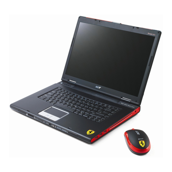
Page 29: Using The Bluetooth Wireless Optical Mouse
Using the Bluetooth Wireless Optical Mouse Your Ferrari series notebook computer comes with a Bluetooth wireless optical mouse, including two rechargeable batteries. Installation Installation of the Bluetooth mouse is simple. Enable Bluetooth functionality by pressing the Bluetooth "Closed communication button on the front panel. Press the Bluetooth button on the base of the Bluetooth mouse front view"... -
Page 30: Using System Utilities
Using System Utilities Acer eManager Innovative Acer eManagement software is designed for easy access to frequently used functions. At the press of Acer Empowering Key, the Acer eManager user interface appears, featuring four main settings -- Acer eSetting, Acer ePresentation, Acer ePowerManagement and Acer eRecovery. -
Page 31: Acer Gridvista
Acer GridVista is a handy utility that offers four pre-defined display settings so you can view multiple windows on the same screen. To access this function, please go to Start, All Programs and click on Acer GridVista. Start All Programs... - Page 32 Double (vertical), Triple (primary at left), Triple (primary at right), or Quad Acer Gridvista is dual-display compatible, allowing two displays to be partitioned independently. Acer GridVista is simple to set up: Run Acer GridVista and select your preferred screen configuration for each display from the taskbar.
-
Page 33: Launch Manager
Note: Launch Manager Launch Manager allows you to set the four easy-launch buttons located above the keyboard. "Easy-launch "Easy-launch buttons" on page 10 buttons" on page 21 for the location of the easy-launch buttons. You can access the Launch Manager by clicking on Start, All Programs, and then Launch Manager to start Start All Programs the application. -
Page 34: Audio
Audio The computer comes with 16-bit high-fidelity AC'97 stereo audio, and dual stereo speakers. Adjusting the Volume "Hotkeys" on page 14 Adjusting the volume on the computer is as easy as pressing some buttons. See "Hotkeys" on page 17 for more information on adjusting the speaker volume. -
Page 35: Touchpad
Touchpad The built-in touchpad is a pointing device that senses movement on its surface. This means the cursor responds as you move your finger across the surface of the touchpad. The central location on the palmrest provides optimum comfort and support. Touchpad Basics Use the touchpad as follows: Move your finger across the touchpad(2) to move the cursor. - Page 36 Function Left button (1) Right button (4) Main touchpad (2) Center button (3) Drag Click and hold. Tap twice (at the Then slide your same speed as finger across the double-clicking a touchpad to drag mouse button); rest the cursor over the your finger on the selection.
-
Page 37: Ejecting The Optical (Cd Or Dvd) Drive Tray
Eject ing the optical (CD or DVD) drive tray To eject the optical drive tray when the computer is turned on, press the drive eject button. When the power is off, you can eject the drive tray using the emergency eject hole. Chapter 1... -
Page 38: Using A Computer Security Lock
Using a Computer Security Lock A security keylock notch, located on the chassis of the computer, lets you connect a Kensington-compatible computer security lock. Wrap the computer security lock cable around an immovable object such as a table or handle of a locked drawer. -
Page 39: Hardware Specifications And Configurations
Hardware Specifications and Configurations Processor Item Specification CPU type AMD Turion 64 processor CPU package µ 754 Pins PGA ZIF socket CPU core voltage Depend on DVI CPU I/O voltage 1.2V Bus Speed 300,400 MHz Stepping Data Cache 64KB, Code Cache 64KB Advanced Transfer Cache 1024 KB System Board Major Chips Item... - Page 40 BIOS Item Specification BIOS vendor Phoenix BIOS Version Phoenix First BIOS BIOS ROM type Flash ROM BIOS ROM size 512KB BIOS package 32 lead of TSSOP BIOS password control Set by setup manual Second Level Cache Item Specification Cache controller Built-in CPU Cache size 2 MB...
- Page 41 Slot 1 Slot 2 Total Memory 512MB 1024MB 1536MB 1024MB 1024MB 1024MB 256MB 1280MB 1024MB 512MB 1536MB 1024MB 1024MB 2048MB LAN Interface Item Specification Supports LAN protocol Gigabit Fast Ethernet connection LAN connector type RJ45 Wireless LAN InviLink. 802.11b/g Wi-Fi CERTIFIED Wireless LAN connector location Left side...
- Page 42 Hard Disk Drive Interface Item HITACHI Model Name HTS541010G9AT00 Capacity (GB) Bytes per sector Logical heads Logical sectors Configuration Interface ATA-6 Capacity (GB) 100 / 80 / 60 / 40 Sector size (Bytes) Recording zones Data heads (physical) 4 / 4 / 3 / 2 Data disks 2 / 2 / 2 / 1 Max.
- Page 43 Item Seagate Model Name ST9100822A Capacity (GB) Guaranteed sectors 195,371,568 Bytes per sector 512P Physical read/write heads Discs Caches(Mbytes) Recording density, BPI (bits/Inch typical) 703,000 Track density. TPI 115,000 (track/Inch typical) Areal density (Gbits/Inch max) Rotational speed (RPM) 4200 Internal data transfer rate OD (Mbytes/sec 48.25 max.) I/O data-transfer rate...
- Page 44 Item Seagate Models ST9100823A ST9100824A ST9120821A Capacity and Interface Formatted Gbytes (512 bytes/sector) Interface Ultra ATA/100 SATA 1.5Gb/s SATA 1.5Gb/s Ultra ATA/100 Ultra ATA/100 Performance Internal Transfer Rate (Mbits/sec) Max. External Transfer Rate (Mbytes/sec) 150 100 150 100 Avg. Sustained Transfer Rate (Mbytes/sec) > >...
- Page 45 Item TOSHIBA Model MK8026GAX Data Storage Physical Per drive, formatted 80GB Data Heads Number of Disks Rotational Speed 5,400rpm Average Latency 5.55ms Interface ATA-2/3/4/5/6 Buffer 16MB Logical Configuration Heads Cylinders 16,383 User Sectors/Track at zone 0 Logical Blocks (LBA) 156,301,488 Data Transfer Rate Max transfer rate to host 100MB/sec...
- Page 46 DVD Multi Drive Item Specification Vendor & model name UJ-845-CQB Performance Specification> Read CD-Audio CD-ROM (mode 1 and mode 2) CD-ROM (mode 2, form 1 and form 2) CD-I (mode 2, form 1 and form 2) CD-I Ready CD-I Bridge CD-R CD-RW Photo CD...
- Page 47 USB Port Item Specification USB compliancy level OHCI USB 2.0 Number of USB port Location Right Side *3 Front Side *1 Audio Port Item Specification Audio Controller AC’ 97 Codec Audio onboard or optional Built-in Mono or Stereo Stereo Resolution 20 bit stereo Digital to analog converter 18 bit stereo Analog to Ditial converter Compatibility...
- Page 48 Specification Keyboard controller PC87541 Keyboard vendor & model name Standard keyboard w launch button embeded Total number of keypads 88-89 keys Acer Fine Touch keyboard 88-key for US 89-key for EU 92-key for JP with 5-degree curve Touchpad with 4-way integrated scroll button...
- Page 49 Item Specification Vendor & model name SAMSUNG / LTN154P LG / LP154W02-B1K1 Size 15.4" 15.4” Resolution Wide SXGA+ Wide SXGA+ Number Of Pixels 1,680 x 1,050 1,680 x 1,050 331.4 x 207.1 Active Area(mm Pixel Pitch(mm) 0.197 0.19725(H) x 0.19725 (V) Number Of Colors 262K 262K...
-
Page 50: Dimensions And Weight
Power Management ACPI Mode Power Management Sleeping State (S3) CPU Power Down VGA Power Down PCMCIA Suspend Audio Power Down Hard Disk Power Down Super I/O Power Down Sleeping State (S4) Also called Hibernate state. System saves all system states and data onto the disk prior to power off the whole system. -
Page 51: System Utilities
Chapter 2 System Utilities BIOS Setup Utility The BIOS Setup Utility is a hardware configuration program built into your computer’s BIOS (Basic Input/ Output System). Your computer is already properly configured and optimized, and you do not need to run this utility. However, if you encounter configuration problems, you may need to run Setup. -
Page 52: Buttons
Buttons Application Launch Buttons Launch Keys Description Launch Button P <Launch manager> Launch Button e <Launch eManager> Specific Keys Wireless Button Wireless enable/disable E-mail Button Launch Outlook Express Bluetooth Button Enable/disable bluetooth Internet Button Launch Internet Explorer NOTE: Detail description and definition of application Launch Buttons, please reference the External spec. Power Button The activity of the power button is as follows: If power button is pressed for less than 1 second then nothing happens. -
Page 53: Hardware Disk Password Function/Password On Boot Function
Hard Disk Password Function/ Password on boot function This feature allows the user to set the password to prevent any unauthorized access to the internal hard disk. If the original HDD come from other machine with password protected, the system just show ” Enter HDD password [ ]”... -
Page 54: Information
System BIOS Ver: S3A11 ATi 009.010.001.000 VGA BIOS Ver: 1A19 KBC Version: xxxxxxxxxxxxxxxxxxxxxx Serial Number Asset Tag Number: Product Ferrari 4000 Manufacturer Name: Acer xxxxxxxxxxxxxxxxxxxxxxxxxxxxxxxx UUID: Help Select Item F5/F6 Change Values Setup Defaults ↑ ↓ ← → Exit Select Menu... -
Page 55: Main
Main This menu provides you the information of the system. PhoenixBIOS Setup Utility Info. Advanced Security Boot Exit Main Item Specific Help System Time: [02:19:31] System Date: [05/06/2005] <Tab>, <Shift-Tab>, or <Enter> selects field. System Memory: 640 KB Extended Memory: 510 MB Video Memory 128 MB... - Page 56 POST D2D Recovery Allow user to enable/disable the Disk-to-Disk recovery Enabled: Enable D2D Help note: Recovery/ Enable Acer disc-to-disc system recovery via Alt+F10 key eRecovery during POST. Disabled: Options: Enable or Disable Disable D2D Recovery/ eRecovery...
-
Page 57: Advanced
Advanced The Advanced screen contains parameters involving your hardware devices. It also provides advanced settings of the system. PhoenixBIOS Setup Utility Info. Main Advanced Security Boot Exit Item Specific Help Serial port A: [Auto] Infraredl Port: [Auto] Configure seroal port A using options: Parallel port: [Auto]... - Page 58 Parameter Description Option Parallel Port Configure serial port B using options: Disabled [Disabled]: No configuration Enabled [Enabled]: User configuration Auto [Auto]: BIOS or OS chooses configuration (OS Controlled) Displayedd when controlled by OS Mode Set the mode for the parallel port using Qutput only options: Bi-directional...
-
Page 59: Security
Security The Security screen contains parameters that help safeguard and protect your computer from unauthorized use. PhoenixBIOS Setup Utility Security Exit Info. Main Advanced Boot Item Specific Help Supervisor Password Is: Clear User Password Is: Clear Supervisor Password HDD Password Is: Clear controls access to the HDD Master ID:... - Page 60 Parameter Description Set Supervisor Password Defines whether a password is required or not while the events defined in this group happened. The following sub-options are all requires the Set User Password Supervisor password for changes and should be grayed out if the user password was used to enter setup.
-
Page 61: Boot
Boot This menu allows the user to decide the order of boot devices to load the operating system. Bootable devices includes the distette drive in module bay, the onboard hard disk drive and the CD-ROM in module bay and onboard LAN device. PhoenixBIOS Setup Utility Boot Info. -
Page 62: Exit
Exit The Exit screen contains parameters that help safeguard and protect your computer from unauthorized use. PhoenixBIOS Setup Utility Exit Info. Main Advanced Security Boot Item Specific Help Exit Saving Changes Exit Dicarding Changes Exit System Setup and save Load Setup Defaults your changes to CMOS. -
Page 63: Machine Disassembly
Chapter 3 Machine Disassembly and Replacement This chapter contains step-by-step procedures on how to disassemble the notebook computer for maintenance and troubleshooting. To disassemble the computer, you need the following tools: Wrist grounding strap and conductive mat for preventing electrostatic discharge Small Philips screw driver Philips screwdriver Plastic flat head screw driver... -
Page 64: General Information
General Information Before You Begin Before proceeding with the disassembly procedure, make sure that you do the following: Turn off the power to the system and all peripherals. Unplug the AC adapter and all power and signal cables from the system. Remove the battery pack. -
Page 65: Disassembly Procedure Flowchart
Disassembly Procedure Flowchart The flowchart on the succeeding page gives you a graphic representation on the entire disassembly sequence and instructs you on the components that need to be removed during servicing. For example, if you want to remove the main board, you must first remove the keyboard, then disassemble the inside assembly frame in that order. - Page 66 Screw List Item Description Acer part No. SCREW M2.0*2.5- 86.A03V7.012 I(NI)(NYLOK) SCREW I2.5*4M- 86.T25V7.013 BKAGHY(M2.5L4) SCREW M2.5*6- 86.T25V7.012 I(BNI)(NYLOK) SCREW M2.5*3-I 86.T23V7.010 BIN(NYLOK) SCREW M2.5*7-I 86.T25V7.008 BIN(NYLOK) SCREW NUT IO 86.T23V7.001 EA1(MBEA1001,REV3 SCREW M2.0*4- 86.A03V7.007 I(BNI)(NYLOK) Chapter 3...
-
Page 67: Removing The Battery Pack
Removing the Battery Pack Release the battery lock. Slide the battery latch. Remove the battery pack. Chapter 3... -
Page 68: Removing The Hdd Module And Mini Pci
Removing the HDD Module and the miniPCI Removing the HDD Module Remove two screws that secure the HDD cover. Remove the HDD cover. Remove the two screws that secure the HDD. Holding the mylar and pull the HDD module out of the main unit. Removing the Memory Remove the two screws that secure the memory cover. -
Page 69: Removing The Minipci
Removing the miniPCI Remove the two screws that secure the miniPCI cover. Remove the miniPCI cover. Release the wireless antenna. Press the latch on left and right side to pop out the miniPCI and remove it. Chapter 3... -
Page 70: Disassembling The Main Unit Into Upper Case And Lower Case
Disassembling the Main Unit into Upper Case and Lower Case Remove the two screws that secure the left and right hinge cover. Remove the left and right hinge cover.Detach the right and the left hinge cover form the main unit. Remove the three screws on the rear of the main unit. - Page 71 14. Close the LCD and remove the upper case from the main unit. Chapter 3...
-
Page 72: Disassembling The Lower Case
Disassembling the Lower Case Remove the ODD from the lower case. Disconnect the right speaker cable from USB cable and disconnect the USB cable from the mainboard. Remove the two screws that secure the USB module. Remove the USB module from the lower case. Disconnect the USB module from the USB module. - Page 73 10. Tear off the mylar on the MDC cable. 11. Disconnect the MDC cable from the mainboard. 12. Remove the two screws that secure the MDC module. 13. Remove the MDC module from the mainboard. 14. Disconnect the cable from MDC board. 15.
- Page 74 20. Tear off the mylar on the right speaker cable. 21. Remove the right speaker from the lower case. 22. Remove the screw that secure the left speaker. 23. Remove the left speaker from the lower case. 24. Remove the two screws thatsecure the audio board. 25.
-
Page 75: Disassembling The Lcd Module And Upper Case
Disassembling the LCD Module and Upper Case Disconnect the LCD cable from the power board. Remove the two screws that secure the power board. Remove another four screws that secure the power board. Remove the power board from the upper case. Tear off the mylar on the touchpad FFC. - Page 76 13. Detach the LCD panel from the upper case assembly. 14. Remove the four screw caps of the LCD bezel. 15. Remove the four screws that secure the LCD bezel. 16. Remove the LCD bezel from the LCD module. 17. Disconnect the inverter power cable and the LVDS cable from the inverter board. 18.
- Page 77 23. Remove the left and right antenna brackets and antenna cable from the LCD cover. 24. Remove the two screws that secure the LCD bar. 25. Remove the LCD bar from the LCD cover. 26. Remove the four screws that secure the right LCD bracket. 27.
-
Page 78: Disassembling The Lcd Module
Disassembling the LCD Module Remove the four screw caps as shown. Then remove the four screws tightening the LCD bezel. Detach the LCD bezel from the LCD module. Then turn the LCD bezel over and remove the microphone. Tear off the type fastening the inverter cable then disconnect the inverter cable then remove the inverter. Remove the six screws holding the LCD to the LCD cover. - Page 79 12. Tear off the tape fastening the antennae set. 13. Then detach the antennae set from the LCD cover. Chapter 3...
-
Page 80: Disassembling The External Modules
Disassembling the External Modules Disassembling the ODD Module Remove the two screws holding the ODD bracket on one side. Remove the two screws holding the ODD bracket on the other side. Remove another two screws on the rear side. Slide the ODD bracket out of the ODD module. Remove the ODD connector from the ODD module. -
Page 81: Chapter 4 Troubleshooting
Troubleshooting Use the following procedure as a guide for computer problems. NOTE: The diagnostic tests are intended to test only Acer products. Non-Acer products, prototype cards, or modified options can give false errors and invalid system responses. Obtain the failing symptoms in as much detail as possible. -
Page 82: System Check Procedures
System Check Procedures External Diskette Drive Check Do the following to isolate the problem to a controller, driver, or diskette. A write-enabled, diagnostic diskette is required. NOTE: Make sure that the diskette does not have more than one label attached to it. Multiple labels can cause damage to the drive or cause the drive to fail. -
Page 83: Memory Check
Memory check Memory errors might stop system operations, show error messages on the screen, or hang the system. Boot from the diagnostics diskette and start the doagmpstotics program (please refer to main board. Go to the diagnostic memory in the test items. Press F2 in the test items. - Page 84 Check the Power Adapter Unplug the power adapter cable from the computer and measure the output voltage at the plug of the power adapter cable. See the following figure Pin 1: +19 to +20.5V Pin 2: 0V, Ground If the voltage is not correct, replace the power adapter. If the voltage is within the range, do the following: Replace the System board.
-
Page 85: Check The Battery Pack
Check the Battery Pack To check the battery pack, do the following: From Software: Check out the Power Management in control Panel In Power Meter, confirm that if the parameters shown in the screen for Current Power Source and Total Battery Power Remaining are correct. -
Page 86: Phoenixbios Post Tasks And Beep Codes
Power-On Self-Test (POST) Error Message The POST error message index lists the error message and their possible causes. The most likely cause is listed first. NOTE: Perform the FRU replacement or actions in the sequence shown in FRU/Action column, if the FRU replacement does not solve the problem, put the original part back in the computer. -
Page 87: Index Of Error Messages
Index of Error Messages Error Code List Error Codes Error Messages Equipment Configuration Error Causes: 1. CPU BIOS Update Code Mismatch 2. IDE Primary Channel Master Drive Error (THe causes will be shown before “Equipment Configuration Error”) Memory Error at xxxx:xxxx:xxxxh (R:xxxxh, W:xxxxh) Real Time Clock Error CMOS Battery Bad CMOS Checksum Error... - Page 88 Error Message List Error Messages FRU/Action in Sequence Real time clock error RTC battery Run BIOS Setup Utility to reconfigure system time, then reboot system. System board Previous boot incomplete - Default configuration Run “Load Default Settings” in BIOS Setup Utility. used RTC battery System board...
- Page 89 Error Message List No beep Error Messages FRU/Action in Sequence No beep, power-on indicator turns off and LCD is Power source (battery pack and power adapter). See “Power blank. System Check” on page 76. Ensure every connector is connected tightly and correctly. Reconnect the DIMM.
-
Page 90: Post Code
POST Code Code Beeps For Boot Block in Flash ROM Initialize the chipset Initialize the bridge Initialize the CPU Initialize the system timer Initialize system I/O Check force recovery boot Checksum BIOS ROM Go to BIOS Set Huge Segment Initialize Multi Processor Initialize OEM special code Initialize PIC and DMA Initialize Memory type... -
Page 91: Index Of Symptom-To-Fru Error Message
Index of Symptom-to-FRU Error Message LCD-Related Symptoms Symptom / Error Action in Sequence LCD backlight doesn't work Enter BIOS Utility to execute “Load Setup Default Settings”, then reboot system. LCD is too dark Reconnect the LCD connectors. LCD brightness cannot be adjusted Keyboard (if contrast and brightness function key doesn't work). - Page 92 PCMCIA-Related Symptoms Symptom / Error Action in Sequence System cannot detect the PC Card (PCMCIA) PCMCIA slot assembly System board PCMCIA slot pin is damaged. PCMCIA slot assembly Memory-Related Symptoms Symptom / Error Action in Sequence Memory count (size) appears different from Enter BIOS Setup Utility to execute “Load Default Settings, then actual size.
- Page 93 Power Management-Related Symptoms Symptom / Error Action in Sequence System hangs intermittently. Reconnect hard disk/CD-ROM drives. Hard disk connection board System board Peripheral-Related Symptoms Symptom / Error Action in Sequence System configuration does not match the Enter BIOS Setup Utility to execute “Load Default Settings”, then installed devices.
-
Page 94: Intermittent Problems
Intermittent Problems Intermittent system hang problems can be caused by a variety of reasons that have nothing to do with a hardware defect, such as: cosmic radiation, electrostatic discharge, or software errors. FRU replacement should be considered only when a recurring problem exists. When analyzing an intermittent problem, do the following: Run the advanced diagnostic test for the system board in loop mode at least 10 times. -
Page 95: Undetermined Problems
System Check” on page 76): Power-off the computer. Visually check them for damage. If any problems are found, replace the FRU. Remove or disconnect all of the following devices: Non-Acer devices Printer, mouse, and other external devices Battery pack Hard disk drive... -
Page 96: Use Napp Cd To Build Master Hard Disc Drive
Use NAPP CD to Build Master Hard Disc Drive CD to Disk Recovery Prepare NAPP CD, Recovery CD and System CD. Put NAPP CD into the optical drive. Then boot up the system. The system will ask you if you want to build NAPP Master HDD. Please press any key to continue. NAPP CD will start to preload the system, please click [Y]. - Page 97 Select CD to Disk Revocery. Put the Recovery CD to the optical drive. This step is to create image files to the system, you do not have to put the Recovery CD to the optical drive in order. Place one Recovery CD to the drive at one time till you finish all Recovery CDs.
- Page 98 Then insert the System CD to the optical drive. You will see the screen displaying “PASS” when the system has buit NAPP Master hard disc drive. Chapter 4...
-
Page 99: Disk To Disk Recovery
Disk to Disk Recovery Prepare NAPP CD, Recovery CD and System CD. Put NAPP CD into the optical drive. Then boot up the system. The system will ask you if you want to build NAPP Master HDD. Please press any key to continue. NAPP CD will start to preload the system, please click [Y]. - Page 100 Select Disk to Disk Recovery. Then choose Single Language or Multi-Languages Recovery. NOTE: For Multi-Languages Recovery, not more than five languages could be loaded to the system. Put the Recovery CD to the optical drive. This step is to create image files to the system, you do not have to put the Recovery CD to the optical drive in order.
- Page 101 After you place the Recovery CD to the optical drive, you will see the display below. Then insert the System CD to the optical drive. Chapter 4...
- Page 102 You will see the screen displaying “PASS” when the system has buit NAPP Master hard disc drive. Chapter 4...
-
Page 103: Jumper And Connector Locations
Chapter 5 Jumper and Connector Locations Top View Chapter 5... -
Page 104: Rear View
Rear View Chapter 5... -
Page 105: Remove Bios Password
Remove BIOS Password Copy MastID program to C Click Start > Program > Accessories > Command Prompt Go to C:directory Run mastid.exe Key in “01234567” as following picture Get master password Chapter 5... -
Page 106: Remove Hdd Password
Remove HDD Password To get HDD mater ID: Power on system Press “F2” to enter CMOS Use right arrow button to move to “Security” (refer to illustration 1) Check HDD Master ID number To get master password: Copy MastID program to C Click Start ->... - Page 107 illustration 2 Chapter 5...
-
Page 108: Fru (Field Replaceable Unit) List
DIFFERENT part number code from those given in the FRU list of this printed Service Guide. You MUST use the local FRU list provided by your regional Acer office to order FRU parts for repair and service of customer machines. -
Page 109: Exploded Diagram
Exploded Diagram Chapter 6... - Page 110 Screw Location Chapter 6...
- Page 111 Chapter 6...
- Page 112 Chapter 6...
-
Page 113: Parts
Parts PICTURE PARTNAME DESCRIPTION ACER P/N ADAPTER ADAPTER LITE- ON PA-1900-05QA ZP1 ADAPTER S/P-LITE-ON S/P AP.A1003.001 3PIN W/LED 90W ADAPTER LSE 0202C1990 3PIN W/ ZP1 ADAPTER S/P-LSE S/P AP.06503.006 LED 90W BATTERY BATTERY SANYO LI-ION 4S2P ZF3 BATTERY Sanyo S/P BT.00803.012... - Page 114 PICTURE PARTNAME DESCRIPTION ACER P/N LCD INVERTER BOARD ZF1 INV (8-20V,V=700,REV=A1A) 19.T72V7.001 S.P. CABLES FFC CABLE - TP/B TO MB ZF1 CABLE TP/ 50.T72V7.001 B(FFC,12P,70MM,REV2A) S.P. MODEM CABLE - MODEM TO MB ZF3 CABLE MODEM(2P/ 50.FR4V7.001 2P,REV1A)L-F S.P. POWER CABLE -POWER TO MB ZF3 CABLE POWER(8P/8P,REV1A)L- 50.FR4V7.002...
- Page 115 PICTURE PARTNAME DESCRIPTION ACER P/N POWER CORD US (3 pin) ET2S POWER CORD S/P-US 27.A03V7.001 POWER CORD PRC ( 3 Pin) ET2S POWER CORD S/P-PRC 27.A03V7.003 POWER CORD KOERA ( Pin) ZI1S POWER CORD SPARE PART- 27.T23V7.006 KOERA POWER CORD EU (3 PIN) ET2S POWER CORD S/P-EU 27.A03V7.002...
- Page 116 PICTURE PARTNAME DESCRIPTION ACER P/N HDD COVER W/RUBBER ZF3 HDD DOOR ASSY S/P 42.FR4V7.007 HDD BRACKET W/MYLAR ZF1 HDD BKT-2 S/P 33.T72V7.003 OPTICAL DEVICE HOLDER-FIX ZF3 DVD HOLDER FIX 42.FR4V7.005 (EBZF1027,REV3B)FER S.P. DVD SUPER MULTI BEZEL SLOT IN ( ZF3 SLOT BEZEL ASSY (PAN.
- Page 117 PICTURE PARTNAME DESCRIPTION ACER P/N CPU/PROCESSOR AMD Mobile Turion 64 ML40,35W,L2 MOBILE TURION 64 ML40 KC.TML02.400 cache:1MB AMD Mobile Turion 64 ML37,35W,L2 MOBILE TURION 64 ML37 KC.TML02.370 cache:1MB AMD Mobile Turion 64 ML34,35W,L2 MOBILE TURION 64 ML34 KC.TML02.340 cache:1MB DVD RW DRIVE...
- Page 118 PICTURE PARTNAME DESCRIPTION ACER P/N TM8100 KEYBOARD DARFON ZF1 K/B ARAB-EN ASSY S.P. KB.T7207.013 ARABIC TM8100 KEYBOARD DARFON ZF1 K/B BELGIUM ASSY S.P. KB.T7207.014 BELGIUM TM8100 KEYBOARD DARFON ZF1 K/B SWEDISH ASSY S.P. KB.T7207.015 SWEDEN TM8100 KEYBOARD DARFON ZF1 K/B CZECH ASSY S.P.
- Page 119 PICTURE PARTNAME DESCRIPTION ACER P/N MAINBOARD MAINBOARD M26-128MB W/PCMCIA ZF3 M/B ASSY S.P. LB.FR406.001 SLOT, 5 IN 1 W/O CPU MEMORY RTC BATTERY RTC BATTERY ML1220 BATTERY LI 3V 14MAH(ML1220)L-F S.P. MEMORY SO-DIMM DDR333 512MB SO-DIMM DDR333 512MB KN.51202.025 HYS64D64020HBDL-6-C 64MX64 HYS64D64020HBDL-6-C 64MX64 (0.11U/GREEN...
- Page 120 PICTURE PARTNAME DESCRIPTION ACER P/N HEATSINK THERMAL MODULE ZF3 THERMAL MODULE ASSY S.P. 60.FR4V7.005 SCREWS SCERW M3*0.5+3.5I SCERW M3*0.5+3.5I 86.A03V7.011 SCERW M2.0*2.5-I(NI)(NYLOK) SCERW M2.0*2.5-I(NI)(NYLOK) 86.A03V7.007 SCERW M2.0*4.0-NI(NYLOK) SCERW M2.0*4.0-NI(NYLOK) 86.FR4V7.001 SCERW M1.6*3.0-NI SCERW M1.6*3.0-NI 86.A10V7.002 SCERW M2.5*2.5-I(NI)(NYLOK) SCERW M2.5*2.5-I(NI)(NYLOK) 86.T25V7.010 SCERW M2.5*4.0-I(BKAG)(NYLOK)
-
Page 121: Appendix A Model Definition And Configuration
Appendix A Model Definition and Configuration Ferrari 4000 series Model Card Wireless Memory Number (GB) Reader 4000 15.4” SODIMM 100GB 5-in-1 802.11 b+g WSXGA DDR333 DVD RW Turion Drive processor Appendix A... -
Page 122: Test Compatible Components
Appendix B Test Compatible Components This computer’s compatibility is tested and verified by Acer’s internal testing department. All of its system ® functions are tested under Windows XP Home environment. Refer to the following lists for components, adapter cards, and peripherals which have passed these tests. -
Page 123: Microsoft Windows Xp(Home/Professional) Environment Test
® ® Microsoft Windows XP Pro Environment Test Item Specifications AMD Mobile Turion 64 ML30,35W,L2 cache:1MB AMD Mobile Turion 64 ML34,35W,L2 cache:1MB AMD Mobile Turion 64 ML37,35W,L2 cache:1MB AMD Mobile Turion 64 ML40,35W,L2 cache:1MB LG, LP154W02-B1K1, 185 nits SAMSUNG, LTN154P1-L02, 185nits Memory Hynix256MB/ 333MHz, HYMD232M646D6-J 256MB/DDR333... - Page 124 Item Specifications TM8100 Keyboard DARFON US International TM8100 Keyboard DARFON Chinese TM8100 Keyboard DARFON Spanish TM8100 Keyboard DARFON Thai TM8100 Keyboard DARFON Brazilian Protugese TM8100 Keyboard DARFON Korea TM8100 Keyboard DARFON UK TM8100 Keyboard DARFON German TM8100 Keyboard DARFON Italian TM8100 Keyboard DARFON French TM8100 Keyboard DARFON Swiss/G TM8100 Keyboard DARFON Portuguese...
-
Page 125: Appendix C Online Support Information
This section describes online technical support services available to help you repair your Acer Systems. If you are a distributor, dealer, ASP or TPM, please refer your technical queries to your local Acer branch office. Acer Branch Offices and Regional Business Units may access our website. However some information sources will require a user i.d.
Need help?
Do you have a question about the Ferrari 4000 and is the answer not in the manual?
Questions and answers