Sony MZ-N505 Service Manual
Service manual
Hide thumbs
Also See for MZ-N505:
- Operating instructions manual (134 pages) ,
- Manual del instrucción (72 pages) ,
- Specifications (2 pages)
Table of Contents
Advertisement
SERVICE MANUAL
Ver 1.0 2002. 01
US and foreign patents licensed from Dolby
Laboratories.
• OpenMG, "MagicGate", "MagicGate Memory Stick", "Memory Stick",
VAIO,MusicClip and their logos are trademarks of Sony Corporation.
• "WALKMAN" is a trademark of Sony Corporation.
• Microsoft,Windows,Windows NT and Windows Media are trademarks
or registered trademarks of Microsoft Corporation in the United States
and/or other countries.
• IBM and PC/AT are registered trademarks of International Business
Machines Corporation.
• Macintosh is a trademark of Apple Computer,Inc.in the United States
and/or other countries.
• All other trademarks are trademarks of their respective owners. ™ and
® marks are omitted in this manual.
Sony Corporation
9-873-459-01
2002A0500-1
Personal Audio Company
C 2002.1
Published by Sony Engineering Corporation
MZ-N505
Model Name Using Similar Mechanism
Mechanism Type
Optical Pick-up Name
SPECIFICATIONS
MD Recorder
Audio playing system
MiniDisc digital audio system
Laser diode properties
Material: GaAlAs MQW
Wavelength: = 790 nm
Emission duration: continuous
Laser output: less than 44.6 W
(This output is the value measured at a distance
of 200 mm from the lens surface on the optical
pick-up block with 7 mm aperture.)
Recording and playback time
When using MDW-80
Maximum 160 min. in monaural
Maximum 320 min. in stereo
Revolutions
Approx. 380 rpm to 2,700 rpm (CLV)
Error correction
ACIRC (Advanced Cross Interleave Reed
Solomon Code)
Sampling frequency
44.1 kHz
Sampling rate converter
Input: 32 kHz/44.1 kHz/48 kHz
PORTABLE MINIDISC RECORDER
US Model
Canadian Model
AEP Model
UK Model
MZ-N707
MT-MZN707-177
LCX-5R
– Continued on next page –
Advertisement
Table of Contents

Related Manuals for Sony MZ-N505


Summary of Contents for Sony MZ-N505
- Page 1 Optical Pick-up Name LCX-5R • OpenMG, “MagicGate”, “MagicGate Memory Stick”, “Memory Stick”, VAIO,MusicClip and their logos are trademarks of Sony Corporation. • “WALKMAN” is a trademark of Sony Corporation. • Microsoft,Windows,Windows NT and Windows Media are trademarks or registered trademarks of Microsoft Corporation in the United States SPECIFICATIONS and/or other countries.
-
Page 2: Battery Life
When using a 100% fully charged rechargeable 120 V AC, 60 Hz (USA, Canada) battery. When using a Sony LR6 (SG) “STAMINA ” 230 V AC, 50/60 Hz (Continental Europe) alkaline dry battery (produced in Japan). 230 - 240 V AC, 50 Hz (UK) -
Page 3: Table Of Contents
MZ-N505 TABLE OF CONTENTS CAUTION Use of controls or adjustments or performance of procedures SERVICING NOTES ..........4 other than those specified herein may result in hazardous ra- diation exposure. GENERAL ..............5 On power sources DISASSEMBLY Use house current, Nickel Cadmium 3-1. -
Page 4: Servicing Notes
MZ-N505 SECTION 1 SERVICING NOTES • Replacement of CXD2677-202GA (IC801) used in this set re- NOTES ON HANDLING THE OPTICAL PICK-UP quires a special tool. BLOCK OR BASE UNIT The laser diode in the optical pick-up block may suffer electro- •... -
Page 5: General
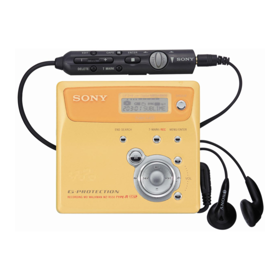
MZ-N505 SECTION 2 This section is extracted from instruction manual. GENERAL Lookingat the controls The display window of the recorder C D E L P 2 . 4 The recorder Digital MEGA BA SS CHARGE MONO (monaural) indication REC indication Lights up while recording. -
Page 6: Disassembly
MZ-N505 SECTION 3 DISASSEMBLY • This set can be disassembled in the order shown below. 3-1. DISASSEMBLY FLOW 3-2. CASE (LOWER) (Page 7) 3-3. CASE (UPPER) SECTION (Page 7) 3-4. LCD MODULE, 3-5. MECHANISM DECK CASE (UPPER) SUB ASSY (MT-MZN707-177) -
Page 7: Case (Lower)
MZ-N505 Note: Follow the disassembly procedure in the numerical order given. 3-2. CASE (LOWER) 1 two screws (M1.4) 1 two screws (M1.4) 2 Remove the case (lower) in the direction of the arrow. 3-3. CASE (UPPER) SECTION 6 case (upper) section... -
Page 8: Lcd Module, Case (Upper) Sub Assy
MZ-N505 3-4. LCD MODULE, CASE (UPPER) SUB ASSY 1 four screws (1.7 2.5) 2 LCD module Note: On installation, adjust the position of both switch and knob (hold). switch 3 button (control) 4 case (upper) sub assy knob (hold) 3-5. -
Page 9: Set Chassis (5188) Assy
MZ-N505 3-6. SET CHASSIS (5188) ASSY 2 two screws (1.7 2.5) 3 set chassis (5188) assy 1 four screws (M1.4 3-7. MAIN BOARD 3 battery case 4 main board 1 battery terminal board (+) 2 battery terminal (–) -
Page 10: Op Service Assy (Lcx-5R)
MZ-N505 3-8. OP SERVICE ASSY (LCX-5R) 2 gear (SA) 5 screw (M1.4) 1 washer (0.8-2.5) 6 thrust detent spring 3 screw (M1.4) 8 Pull off lead screw. 4 rack spring 9 Opening the over write head toward the direction A , remove the OP service assy (LCX-5R) toward the direction B . -
Page 11: Holder Assy
MZ-N505 3-9. HOLDER ASSY 4 holder assy 2 Open the holder assy 3 boss 1 convex portion 3 boss 3-10. DC MOTOR (SLED) (M602) 2 washer (0.8-2.5) 3 gear (SA) 4 two screws (M1.4) 1 Remove six solders of the motor flexible board. -
Page 12: Dc Ssm18B Motor (Spindle) (M601)
MZ-N505 3-11. DC SSM18B MOTOR (SPINDLE) (M601), DC MOTOR (OVER WRITE HEAD UP/DOWN) (M603) 1 Remove six solders of the motor flexible board. 2 tapping screw 3 motor cover 7 DC motor (over write head up/down) (M603) Note: Press-fit the gear (HA) up to the position of the DC motor (over write head up/down) (M603) as shown below. -
Page 13: Test Mode
MZ-N505 SECTION 4 TEST MODE OUTLINE OPERATION IN SETTING THE TEST MODE • This set provides the Overall adjustment mode that allows CD • When the test mode becomes active, first the display check mode and MO discs to be automatically adjusted when in the test mode. - Page 14 MZ-N505 CONFIGURATION OF TEST MODE [Major item switching] [VOL +] key: 100th place of item number increase. [Test Mode $Display Check Mode%] [VOL --] key: 100th place of item [VOL +] Press the > number decrease. [Manual Mode] Press the...
- Page 15 MZ-N505 5. The display changes a shown below each time the OVERALL ADJUSTMENT MODE [MENU/ENTER] key . Mode to adjust the servo automatically in all items. Normally, automatic adjustment is executed in this mode at the repair. For further information, refer to “SECTION 5 ELECTRICAL •...
- Page 16 MZ-N505 • Description of Error Indication Codes Problem Indication code Meaning of code Simple display Description No error No error No error Illegal access target Adrs Attempt to access an abnormal address address was specified Servo system error High temperature...
- Page 17 MZ-N505 SOUND SKIP CHECK RESULT DISPLAY MODE • Cause of Sound Skip Error This set can display the count of errors that occurred during the Cause of error Description of error recording/playing for checking. Sound error correction error • Setting Method of Sound Skip Check Result Display...
- Page 18 MZ-N505 4. When all the keys on the set and on the remote commander are considered as OK, the following displays are shown for 4 sec- onds. Example1: When the keys on the set are considered as OK: Set LCD display...
-
Page 19: Electrical Adjustments
2. Use the following tools and measuring instruments. • Test CD disc TDYS-1 (Part No. : 4-963-646-01) ###SCC • SONY MO disc available on the market • Digital voltmeter ### : Address • Laser power meter LPM-8001 (Part No. : J-2501-046-A) 2. - Page 20 MZ-N505 • Change of NV Adjusted Values (version 1.100) 9) Press the key to write the adjusted value. Caution: Change the NV adjustment values according to the mi- 10) Select manual mode of the test mode, and set item number crocomputer version.
- Page 21 MZ-N505 [VOL +] [VOL --] 23) Adjust with the key (adjusted value up) or 37) Select manual mode of the test mode, and set item number key (adjusted value down) so that the adjusted value becomes 865 (see page 14).
- Page 22 MZ-N505 49) Select manual mode of the test mode, and set item number POWER SUPPLY MANUAL ADJUSTMENT 871 (see page 14). • Adjustment Sequence Adjustment must be done with the following steps. Set LCD display 1. Vc PWM Duty (L) adjustment (item number: 762) ###S** 2.
- Page 23 MZ-N505 2. Press the key to write the adjusted value. 1. Connect a digital voltmeter to the TP (VREC) on the MAIN [VOL +] [VOL --] board, and adjust key (voltage up) or Adjustment and Connection Location: MAIN board (voltage down) so that the voltage becomes 1.13 0.02 V.
- Page 24 MZ-N505 LASER POWER CHECK 11. Check that the laser power meter reading is 4.95 0.50 mW. 12. Check that the voltage both ends (TP (+) and TP (–)) of resis- • Connection laser tor R521 at this time is below 80 mV.
- Page 25 MZ-N505 Adjustment/checking and Connection Location: – MAIN Board (Component Side) – TP ( ) C803 Q501 F801 S806 (OPEN/CLOSE DETECT) L502 C630 L501 L902 J302 R105 C316 R853 L901 TP ( + ) – MAIN Board (Conductor Side) – AP913 (VLO)
- Page 26 MZ-N505 OVERALL ADJUSTMENT MODE • Overall adjustment mode (title display) • Configuration of Overall Adjustment Mode Set LCD display Overall adjustment mode (Title display) Assy** Protect switch CD overall : (Disc mark) At end of power supply adjustment: Outside lit adjusting At end of electrical offset adj.: Inside lit...
- Page 27 MZ-N505 3. Insert CD disc in the set, and press thethe key to set the • CD and MO Overall Adjustment Items CD overall adjustment mode. Automatic adjustments are made. 1. CD overall adjustment items Item No. Description Set LCD display...
- Page 28 MZ-N505 RESUME CLEAR Perform the Resume clear when all adjustments completed. • Resume Clear Setting Method 1. Select the manual mode of the test mode, and set item number 043 (see page 14). Set LCD display ###S00 ### : Address 2.
- Page 29 MZ-N505 REWRITING THE PATCH DATA AT REPLACEMENT OF MAIN BOARD OR NONVOLATILE MEMORY (IC804) This set requires the patch data in the nonvolatile memory (IC804) to be rewritten using the application, when the MAIN board or nonvolatile memory (IC804) was replaced.
- Page 30 MZ-N505 5. Confirm that the model and version indicated on the title bar coincide with the codes displayed in the Device Name block and the Version block in the window. 6. Click the [Write + Verify] button. The patch data writing and the verify processing will be executed automatically in the following order:...
- Page 31 MZ-N505 8. Click the [Usb Disconnect] button. 9. Confirm that the window becomes as shown below where the [Write + Verify] button and [Read] button are inactive. 10. Disconnect the USB cable from the personal computer and the set.
-
Page 32: Diagrams
MZ-N505 SECTION 6 DIAGRAMS 6-1. BLOCK DIAGRAM – SERVO/USB Section – OVER WRITE HEAD DRIVE IC601 (1/2) HR601 OVER WRITE OVER HEAD DRIVE OPTICAL PICK-UP BLOCK PRE DRIVER WRITE Q604, 605 (LCX-5R) HEAD (Page 34) VRECIN2 OUTA VRECO H-BRIDGE M603... -
Page 33: Block Diagram - Audio Section
MZ-N505 6-2. BLOCK DIAGRAM – AUDIO Section – OPTICAL RECEIVER B+ SWITCH VIF B+ Q302 DIN1 (Page 32) J301 LINE IN (OPTICAL) (LINE IN JACK) A/D CONVERTER IC301 LIN2 AUDIO ADDT GAIN SDTO CONVERTER (Page 32) & CONTROL RIN2 SDO0... -
Page 34: Block Diagram - Display/Key Control/Power Supply Section
MZ-N505 6-3. BLOCK DIAGRAM – DISPLAY/KEY CONTROL/POWER SUPPLY Section – RMC KEY (Page 33) VRMC HEADPHONE AMP (IC302), XWK3 MOTOR/COIL DRIVER (IC551) RMC KEY CLK SEL CLK SEL FFCLR FFCLR SLEEP SLEEP SYSTEM VLON (Page 32) CONTROL VLON XWK1 POWER CONTROL... -
Page 35: Note For Printed Wiring Board And Schematic Diagrams
MZ-N505 6-4. NOTE FOR PRINTED WIRING BOARD AND SCHEMATIC DIAGRAMS Note on Printed Wiring Board: Note on Schematic Diagram: • X : parts extracted from the component side. • All capacitors are in F unless otherwise noted. pF: • Y : parts extracted from the conductor side. -
Page 36: Printed Wiring Board - Main Board (Component Side)
MZ-N505 6-5. PRINTED WIRING BOARD – MAIN Board (Component Side) – :Uses unleaded solder. • Semiconductor Location Ref. No. Location D601 D603 D607 D803 D804 D904 S805 OPEN IC551 IC604 IC804 Q302 Q501 CN701 FB703 (1/2) Q601 FB702 (USB CONNECTOR) -
Page 37: Printed Wiring Board - Main Board (Conductor Side)
MZ-N505 6-6. PRINTED WIRING BOARD – MAIN Board (Conductor Side) – :Uses unleaded solder. • Semiconductor Location Ref. No. Location MAIN BOARD (CONDUCTOR SIDE) D101 D201 D301 S803 D602 RECHARGEABLE BATTERY PROTECT NC-WMAA D606 H-10 DETECT M602 1PC. 1.2V (SLED) -
Page 38: Schematic Diagram - Main Board (1/4)
MZ-N505 6-7. SCHEMATIC DIAGRAM – MAIN Board (1/4) – • See page 42 for Waveforms. • See page 43 for IC Block Diagrams. (1/4) (Page 40) TP611 HR601 OVER WRITE TP610 HEAD (VREC) CN501 TRK- TRK- Q604 TRK+ R507 C501... -
Page 39: Schematic Diagram – Main Board (2/4)
MZ-N505 6-8. SCHEMATIC DIAGRAM – MAIN Board (2/4) – • • See page 42 for Waveform. See page 43 for IC Block Diagrams. (2/4) D904 MA111-TX R914 C522 R906 R946 0.5% C901 C902 C919 R909 R910 10 6.3V 6.3V 6.3V R915 2.2k... -
Page 40: Schematic Diagram – Main Board (3/4)
MZ-N505 6-9. SCHEMATIC DIAGRAM – MAIN Board (3/4) – • See page 42 for Waveforms. (3/4) DIN1 C839 1000p (Page R807 C809 FB801 FB806 C817 6.3V R858 C838 R857 R825 2.2M R832 R824 470k 2.2k C833 C808 R823 R821 220k... -
Page 41: Schematic Diagram - Main Board (3/4)
MZ-N505 6-10. SCHEMATIC DIAGRAM – MAIN Board (4/4) – • See page 42 for Waveforms. • See page 43 for IC Block Diagrams. (4/4) EEPROM R830 IC804 AK6417AM SCK0 C823 XBUSY SDO0 SDI0 J301 Q302 R316 LINE IN 2SA2018TL 100k... - Page 42 MZ-N505 • Waveforms 7 IC901 th (CLK) qs IC801 <z,z (TE) qj IC301 0 (BCLK) (REC mode) 1 IC501 1 (TE) 1 Vp-p 2.2 Vp-p 200 mVp-p 200 mVp-p 5.67 ns 354 ns 3 IC501 ed (RF OUT) 8 IC801 <zc, (UOSCO) (USB mode) qd IC801 <z.n (LRCK) (REC mode)
- Page 43 MZ-N505 • IC Block Diagrams IC301 AK5354VT-E2 16 PDN LIN1 15 CSN CONTROL IPGA 14 CCLK RIN1 REGISTER LIN2 13 CDTI RIN2 CLOCK DIVIDER VCOM 12 LRCK AGND 11 MCLK AUDIO I/F CONTROLLER 10 BCLK 9 SDTO IC302 TA2131FL (EL)
- Page 44 MZ-N505 IC501 SN761057A ADIP-IN S-MON A+B+C+D TWpp PK/BTM CSLO REXT VREF075 Wpp LPF Aw+Dw S-MONITOR TON Peak VREF TON Botm Malfa ADIP AwBPF TEMP DwBPF Tpp/Wpp ABCD OFC-C1 OFC-C2 AVCC AGND CCSL2 ABCD VREF075 PEAK PEAK/BOTM BOTM TON-C OF TRK...
- Page 45 MZ-N505 IC551 SC111258FCR2 42 41 35 34 31 30 29 PWM2 3PHASE CONTROL 3PHASE H-BRIDGE H-BRIDGE PRE DRIVER PRE DRIVER CONTROL VC LOW VOLTAGE DETECTOR COM2 CPUI2 – CPUO2 CPVO2 – CPVI2 CPWO2 – CPWI2 BIAS GND2 VC VG GND1 –...
- Page 46 MZ-N505 IC601 XPC18A22AFCR2 VC2 VG CHARGE OUTPUT SW OUTPUT SW CHARGE PUMP 1 PUMP 2 VC VG DC IN HI-BRIDGE CHARGE PRE DRIVER PRE DRIVER MONITOR VREF VREF X2/X4 BATM BUFFER DC IN CVREF CONTROL CONTROL CHARGE CHGSW DW BT...
- Page 47 MZ-N505 IC901 XPC18A32FCR2 36 35 34 33 32 31 30 29 OUTPUT OUTPUT SW SERIES PASS SERIES PASS SERIES PASS OUTPUT SW REGULATOR VA REGULATOR VD REGULATOR VIF POWER – SWITCH 1 INM1 STEP-UP PRE DRIVER DTC1 XRST OUTPUT SW...
-
Page 48: Ic Pin Function Description
MZ-N505 6-11. IC PIN FUNCTION DESCRIPTION IC501 SN761057A (RF AMP, FOCUS/TRACKING ERROR AMP) Pin No. Pin Name Description Tracking error signal output to the system controller REXT — Connect terminal to the external resistor for the ADIP amplifier control WPP-LPF —... - Page 49 MZ-N505 IC801 CXD2677-202GA (SYSTEM CONTROLLER, DIGITAL SIGNAL PROCESSOR, 16M BIT D-RAM) Pin No. Pin Name Description Load address strobe signal output terminal for D-RAM Not used Test input terminal for D-RAM Not used 3 to 7 Address signal output terminal for D-RAM Not used...
- Page 50 MZ-N505 Pin No. Description Pin Name Data input terminal Not used TRST Input terminal for the test mode set (normally fixed at “L”) XOPT CTL Power supply ON/OFF control signal output for the DIN PD drive VG CTL VG power supply voltage control signal output terminal Not used...
- Page 51 MZ-N505 Pin No. Pin Name Description XMUTE Analog muting control signal output terminal “L”: muting ON Not used XRST System reset signal input from the power control “L”: reset STAND DET Charging stand detection signal input terminal Not used VB MON...
- Page 52 MZ-N505 Pin No. Description Pin Name VSIOSC — Ground terminal (for the OSC cell) — DAVDD Power supply terminal (for the built-in D/A converter) (+2.4V) VREFL Reference voltage input terminal (for the built-in D/A converter L-CH) AOUTL Built-in D/A converter (L-CH) output terminal...
- Page 53 MZ-N505 Pin No. Pin Name Description Ground terminal Clock signal input from the external VCO Not used — DVSS3 Ground terminal (for the DSP block) — DVDD3 Power supply terminal (for the DSP block) (+1.5V) ADFG ADIP duplex FM signal (20.05 1kHz) input from the RF amplifier...
- Page 54 MZ-N505 Pin No. Description Pin Name EVA/FLASH chip discrimination input terminal “L”: FLASH chip, “H”: EVA chip (fixed at “L” in this set) — FLASHVDD Power supply terminal (for the built-in flash memory) (+2.4V) — FLASHVSS Ground terminal (for the built-in flash memory) 249 to —...
-
Page 55: Exploded Views
MZ-N505 SECTION 7 EXPLODED VIEWS NOTE: The components identified by • -XX and -X mean standardized parts, so they • Items marked “*” are not stocked since they mark 0 or dotted line with mark 0 are critical for safety. -
Page 56: Chassis Section
MZ-N505 7-2. CHASSIS SECTION MT-MZN707-177 main board section Ref. No. Part No. Description Remark Ref. No. Part No. Description Remark 3-237-072-01 SCREW (MD), STEP 3-318-382-91 SCREW (1.7X2.5), TAPPING 3-238-127-01 SPACER (HOLDER) 3-237-080-01 SLIDER, OPEN X-3381-385-1 CHASSIS (5188) ASSY, SET 3-237-082-11 SPRING (LOCK), TENSION... -
Page 57: Main Board Section
MZ-N505 7-3. MAIN BOARD SECTION Ref. No. Part No. Description Remark Ref. No. Part No. Description Remark 3-237-079-01 CASE, BATTERY (for BLUE, GOLD, SILVER) 3-237-074-01 TERMINAL (–), BATTERY 3-237-079-11 CASE, BATTERY (for YELLOW) * 104 X-3381-934-1 MAIN BOARD, COMPLETE (EXCEPT US) -
Page 58: Mechanism Deck Section-1 (Mt-Mzn707-177)
MZ-N505 7-4. MECHANISM DECK SECTION-1 (MT-MZN707-177) mechanism deck section-2 not supplied The components identified by Les composants identifiés par une mark 0 or dotted line with marque 0 sont critiques pour la mark 0 are critical for safety. sécurité. Replace only with part num- Ne les remplacer que par une pièce... -
Page 59: Mechanism Deck Section-2 (Mt-Mzn707-177)
MZ-N505 7-5. MECHANISM DECK SECTION-2 (MT-MZN707-177) M602 M603 M601 Ref. No. Part No. Description Remark Ref. No. Part No. Description Remark 3-225-278-11 SCREW, TAPPING 3-235-839-01 LEVER (RACK) 3-235-838-01 COVER, MOTOR 3-338-645-31 WASHER (0.8-2.5) 3-235-836-01 GEAR (HB) 4-222-222-01 GEAR (RACK) 3-222-544-01 GEAR (HA) -
Page 60: Electrical Parts List
MZ-N505 SECTION 8 MAIN ELECTRICAL PARTS LIST NOTE: • Due to standardization, replacements in the • Items marked “*” are not stocked since they The components identified by mark 0 or dotted line with mark parts list may be different from the parts speci- are seldom required for routine service. - Page 61 MZ-N505 MAIN Ref. No. Part No. Description Remark Ref. No. Part No. Description Remark C604 1-164-943-11 CERAMIC CHIP 0.01uF C828 1-125-837-11 CERAMIC CHIP 6.3V C829 1-125-837-11 CERAMIC CHIP 6.3V C605 1-164-937-11 CERAMIC CHIP 0.001uF C830 1-125-777-11 CERAMIC CHIP 0.1uF C606...
- Page 62 MZ-N505 MAIN Ref. No. Part No. Description Remark Ref. No. Part No. Description Remark D901 8-719-081-33 DIODE MA2YD1500LS0 L902 1-419-949-21 CHOKE COIL 22uH D902 8-719-081-33 DIODE MA2YD1500LS0 L904 1-414-398-11 INDUCTOR 10uH D903 8-719-420-51 DIODE MA729-TX L905 1-469-426-21 INDUCTOR 100uH D904...
- Page 63 MZ-N505 MAIN Ref. No. Part No. Description Remark Ref. No. Part No. Description Remark R315 1-218-965-11 RES-CHIP 1/16W R316 1-218-977-11 RES-CHIP 100K 1/16W R802 1-208-903-11 METAL CHIP 4.7K 0.5% 1/16W R317 1-218-941-11 RES-CHIP 1/16W R803 1-208-927-11 METAL CHIP 0.5% 1/16W...
- Page 64 MZ-N505 MAIN Ref. No. Part No. Description Remark Ref. No. Part No. Description Remark R908 1-218-977-11 RES-CHIP 100K 1/16W ACCESSORIES R909 1-218-965-11 RES-CHIP 1/16W ************ R910 1-218-965-11 RES-CHIP 1/16W 1-476-303-11 REMOTE CONTROL UNIT (RM-MZ4R) R911 1-218-949-11 RES-CHIP 1/16W (AEP, UK, FR)
- Page 65 MZ-N505 MEMO...
-
Page 66: Revision History
MZ-N505 REVISION HISTORY Clicking the version allows you to jump to the revised page. Also, clicking the version at the upper right on the revised page allows you to jump to the next revised page. Ver. Date Description of Revision...