Table of Contents
Advertisement
Quick Links
Advertisement
Table of Contents

Related Manuals for Acer Aspire E1-531


Summary of Contents for Acer Aspire E1-531
- Page 1 ASPIRE xxxx S E R V I C E G U I D E G U I D E...
-
Page 2: Table Of Contents
Table of Contents Chapter 1. Hardware Specifications and Configurations Features ............1-2 Notebook Tour . - Page 3 DIMM Module Installation ........3-22 HDD Module Removal .
- Page 4 USB Failure ........... 4-12 Wireless Function Failure .
-
Page 5: Revision History
Copyright Copyright © 2012 by Acer Incorporated. All rights reserved. No part of this publication may be reproduced, transmitted, transcribed, stored in a retrieval system, or translated into any language or computer language, in any form or by any means, electronic, mechanical, magnetic, optical, chemical, manual or otherwise, without the prior written permission of Acer Incorporated. - Page 6 Conventions The following conventions are used in this manual: WARNING: Indicates a potential for personal injury. CAUTION: Indicates a potential loss of data or damage to equipment. IMPORTANT: Indicates information that is important to know for the proper completion of a procedure, choice of an option, or completing a task.
-
Page 7: General Information
For Acer-authorized service providers: Your Acer office may have a different part number code than those given in the FRU list of this printed service guide. The list provided by your regional Acer office must be used to order FRU... - Page 8 CHAPTER Hardware Specifications and Configurations Hardware Specifications and Configurations ....1-2 Features ............1-2 Notebook Tour .
-
Page 9: Chapter 1. Hardware Specifications And Configurations
Hardware Specifications and Configurations Features The following is a summary of the computer’s many features: Operating System ® • Genuine Windows 7 Home Premium (64-bit) ® • Genuine Windows 7 Home Basic (64-bit) ® • Support to Genuine Windows Platform ®... -
Page 10: Privacy Control
® • Intel HD Graphics 3000/4000 with 128 MB of dedicated system memory, supporting ® ® Microsoft DirectX 10.1 Discrete ® • NVIDIA GT620M with 1024 MB of dedicated DDR3 VRAM, supporting Shader Model ® ® ® 5.0, Microsoft DirectX 11.0, OpenGL 4.1 or later, PhysX™, CUDA™, PCI Express 2.0/3.0, HDMI 1.4a (supporting standard stereo modes for 720p and 1080p), and... -
Page 11: Special Keys And Controls
• External display (VGA) port • 3.5 mm headset/speaker jack • Microphone-in jack • Ethernet (RJ-45) port • DC-in jack for AC adapter Special Keys and Controls Keyboard • 103/104/107-key Fine Tip keyboard • International language support • Independent standard numeric keypad, pgdn/pgup/home/end keys Touchpad •... -
Page 12: Optional Accessories
• Non-operating: 5% to 95% Optional Accessories • 65 W / 90 W AC adapter • 8-cell Li-ion battery pack • HDD pack • CD-ROM Module Hardware Specifications and Configurations... -
Page 13: Notebook Tour
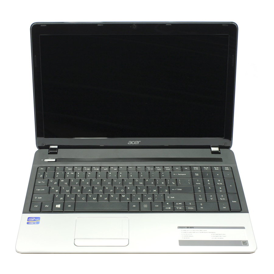
Notebook Tour Top View Figure 1:1. Top View Icon Item Description Press to turn the computer on or off. The indicator lights Power Button blue when the power is on. Touch-sensitive pointing device that functions like a Touchpad computer mouse. Keyboard Use to enter data into the computer. -
Page 14: Front View
Front View Figure 1:2. Closed Front View Icon Item Description Insert a memory card such as Secure Digital (SD), MultiMedia Card (MMC), Memory Stick PRO (MS PRO), and xD-Picture Card (xD) for Multi-in-1 MULTIMEDIACARD external storage. Card Reader NOTE: Only one card can be inserted at a time. Indicates the computer power status: •... -
Page 15: Left View
Left View Figure 1:3. Left View Icon Item Description DC-In Jack Connects to an AC adapter. Ethernet (RJ-45) Connects to an Ethernet 10/100/1000-based network. Port Use for air flow. Air Vents CAUTION: Do not cover the air vents. VGA Port Connects to a VGA cable for external video output. -
Page 16: Right View
Right View Figure 1:4. Right View Icon Item Description USB Ports Connects to USB 2.0 devices. Optical Drive Reads and writes CD and DVD discs. Connects to a Kensington-compatible computer security lock. NOTE: Wrap the computer security lock cable around an Kensington Lock immovable object such as a Slot... -
Page 17: Base View
Base View Figure 1:5. Base View Icon Item Description Battery Bay Houses the computer battery pack. Battery Release Insert a suitable tool into the latch and slide to Latch release the battery. HDD and Memory Compartment Houses the computer HDD and main memory. Cover Hardware Specifications and Configurations 1-10... -
Page 18: Touchpad Basics
Touchpad Basics Figure 1:6. Touchpad Item Description Move your finger across the touchpad to move the cursor. Touchpad Tapping on the touchpad is the same as clicking the left mouse button. Press the left button to perform selection and execution Left Button functions. -
Page 19: Keyboard Basics
Keyboard Basics Figure 1:7. Keyboard Item Description When Caps Lock is on, all alphabetic characters are Caps Lock Key typed in uppercase. Use with other key combinations to perform special Function Key functions. • Press to launch the Start menu. Windows Key •... -
Page 20: Windows Key
Windows Key The table below shows the different functions that Windows key combinations can do: Table 1:2. Windows Key Combinations Key Combination Description Opens or closes the Start menu. Opens the Run dialog box. + <R> Minimizes all windows. + <M> Undo immunize all windows. -
Page 21: Hotkeys
Hotkeys Hotkeys or function key combinations can be used to access computer control functions such as screen brightness, volume, and multimedia playback controls. Table 1:3. Hotkey Combinations Function Icon Description Combination Communication Enables/disables wireless connectivity of <F3> Switch your computer. Switches the display output between the Display Toggle <F4>... -
Page 22: System Block Diagram
System Block Diagram Figure 1:8. System Block Diagram 1-15 Hardware Specifications and Configurations... -
Page 23: Specifications Table
Specifications Table Computer specifications Item Metric Imperial Dimensions Length 381.6 mm 15 in Width 253 mm 9.96 in Height (front to rear) 33.2 mm 1.3 in Weight (equipped with optical 2.6 kg 5.74 lbs drive, flash drive, and battery) Input power Operating voltage 18.55V ~ 19.95V 65W 3.42A (Max) - Page 24 System Board Major Chips Item Specification Core logic Intel Panther Point PCH Intel NVIDIA N13M-GS 1G (GT620M) Broadcom BCM57785 GbE Controller USB 2.0 Intel HM77/HM70 Series Chipset (Panther Point) Super I/O controller Bluetooth Wireless Qualcomm / Broadcomm / Realtek PCMCIA Audio codec Realtek ALC271X-GR-VB6 Card reader...
- Page 25 CPU Fan True Value Table (Tj=100) CPU Temp Fan Speed (RPM) SPL Spec (dBA) Throttling 50%: On= 95 °C; OFF=85 °C OS shut down at 100 °C; H/W shut down at 92 °C System Memory Item Specification Memory controller Built-in at CPU Memory size 1GB, 2GB, 4GB DDR3 RAM x 2 Sockets:...
- Page 26 Memory Combinations Slot 1 (MB) Slot 2 (MB) Total Memory (MB) 1024 1024 2048 2048 4096 4096 1024 1024 1024 1024 2048 1024 2048 3072 1024 4096 5120 2048 2048 2048 1024 3072 2048 2048 4096 2048 4096 6144 4096 4096 4096 1024...
- Page 27 • DMI utility for BIOS serial number configurable/asset tag • Support PXE • Support WinFlash • Wake on LAN from S3 • Wake on LAN from S5 in AC mode • System information • Refer to Acer BIOS specification. LAN Interface Item Specification LAN Chipset Broadcom BCM57785...
- Page 28 Hard Disk Drive (Listed items from AVL list) Item Specification HTS545025B9A HTS545032B9A HTS545050B9A MK6465GSX Vendor & Model Name MK2565GSX MK3265GSX MK5065GSX ST9250315AS ST9320310AS ST9500325AS Capacity 250GB 320GB 500GB 640GB (GB) Bytes per 512 BYTE 512 BYTE 512 BYTE 512 BYTE sector Data heads Drive Format...
- Page 29 Hard Disk Drive Interface (continued) Item Specification WD7500BPVT- ST9750423AS WD2500BPVT- WD3200BPVT- 22HXZT1 22ZEST0 22ZEST0 Vendor & Model MK7559GSXP Name HTS547575A9 E384 Capacity (GB) 750GB 750GB 250GB 320GB Bytes per sector 4096 4096 4096 4096 Data heads Drive Format Disks Spindle speed 5400RPM (RPM) Performance Specifications...
- Page 30 Hard Disk Drive Interface (continued) Item Specification Vendor & WD5000BPVT- WD6400BPVT- Model Name 22HXZT1 22HXZT1 Capacity 500GB 640GB (GB) Bytes per 4096 4096 sector Data heads Drive Format Disks Spindle 5400RPM speed (RPM) Performance Specifications Buffer size Interface SATA Fast data transfer rate 3.0Gbits/s 3.0Gbits/s...
- Page 31 Super-Multi Drive Item Specification HLDS Super-Multi Drive DL 8X GT51N LF / Panasonic Super- Multi Drive DL 8X UJ8B0AW / PLDS Super-Multi Drive DL 8X Vendor & Model name DS-8A8SH / Panasonic Super-Multi Drive DL 8X UJ8C0ADAA1-B LF / Pioneer Super-Multi Drive DL 8X DVR- TD11RS LF Performance Specification With CD Diskette...
- Page 32 LED 15.6” Item Specification • AUO/B156XW02 V6 (HW:0A) Vendor/Model name • AUO/B156XW02 V2 (HW:4A) • Samsung/LTN156AT02-A11 • LG/LP156WH2-TLEA • CMO/N156B6-L0B • CPT/ CLAA156WB11A Screen Diagonal (mm) 394.91 mm Active Area (mm) 344.23 mm x 193.54 mm Display resolution (pixels) 1366 x 3(RGB) x 768 Pixel Pitch (mm) 0.252mm ×...
- Page 33 Graphics Controller and VRAM Item Specification Graphics Controller Chip NVIDIA N13M-GS (GT620M) • Support for Window7 DirectX compute • Direct X11 and Shader Model5.0 • OpenGL3.2 Supports • NVIDIA PhysX technology • NVIDIA CUDA technology • NVIDIA Optimus technology VRAM Chipset Hynix Memory Size Interface...
- Page 34 Bluetooth Interface (N/A) Item Specification Chipset Data throughput Protocol Interface Connector type Supported protocol (List only supported protocols from Acer specs) Bluetooth Module (N/A) Item Specification Controller Features Camera Item Specification • Liteon, 10P2SF205 • Suyin, HF2015-A821-OV01 Vendor and Model •...
- Page 35 Audio Codec and Amplifier Item Specification Audio Controller Audio codec: Realtek ALC271X-GR Audio Interface Item Specification Audio Controller Realtek ALC271X-GR Audio onboard or optional On board Mono or Stereo Stereo Resolution Support 16/24bit PCM Compatibility HD audio Interface Sample rate up to 192Khz resolution VSR (Variable Sampling Sampling rate Rate) Internal microphone...
- Page 36 Battery (continued) Item Specification Vendor & Model name SONY AS10D41 SAMSUNG AS10D61 Battery Type Li-ion Li-ion Pack capacity 4400 mAh 4400 mAh Number of battery cell Package configuration 3S2P 3S2P Item Specification Vendor & Model name PANASONIC AS10D51 Battery Type Li-ion Pack capacity 4400 mAh...
- Page 37 AC Adapter Item Specification 65 W & 90 W Input rating 65 W: 1.5A at 100V Maximum input AC current 90 W: 1.7A at 100V 12t at 264V, no damage to adapter Inrush current Refer to EPA 2.0 Efficiency System Power Management Item Specification Mech.
- Page 38 System LED Indicator Item Specification Lock • Blue color solid on: System on System state • Blue color and amber color off: System off • Amber color blinking: S3 state HDD access state Reflects the activities of the HDD or Card reader access Wireless state •...
- Page 39 System Interrupt Specification (N/A) Hardware IRQ System Function IRQ0 IRQ1 IRQ2 IRQ3 IRQ5* IRQ6 IRQ7* IRQ8 IRQ9* IRQ10* IRQ11 IRQ12 IRQ13 IRQ14 IRQ15 NOTE: Default configuration; audio possible configurations are IRQ5, IRQ7, IRQ9, IRQ10, or none. NOTE: ExpressCards may assert IRQ3, IRQ4, IRQ5, IRQ7, IRQ9, IRQ10, IRQ11, or IRQ15. Either the infrared or the serial port may assert IRQ3 or IRQ4.
- Page 40 I/O Address (hex) System Function (Shipping Configuration) 044 - 05F 062 - 063 065 - 06F 070 - 071 072 - 07F 080 - 08F 090 - 091 093 - 09F 0A0 - 0A1 I/O Address (hex) 0A2 - 0BF 0C0 - 0DF 0E0 - 0EF 0F0 - 0F1...
- Page 41 System IO Address Specification (N/A) I/O Address (hex) System Function (Shipping Configuration) 220 - 22F 230 - 26D 26E - 26 278 - 27F 280 - 2AB 2A0 - 2A7 2A8 - 2E7 2E8 - 2EF 2F0 - 2F7 2F8 - 2FF 300 - 31F 320 - 36F 370 - 377...
- Page 42 CHAPTER Diagnostic Utilities System Utilities ......... .2-2 BIOS Setup Utility .
-
Page 43: Chapter 2. System Utilities
System Utilities BIOS Setup Utility The BIOS Setup Utility is a hardware configuration program built into a computer’s BIOS (Basic Input/Output System). The BIOS utility is pre-configured and optimized so most users do not need to run this utility. However, if configuration problems occur, you may need to run the BIOS utility. To activate the BIOS Utility, press F2 during POST (power-on-self-test) when the “Press <F2>... -
Page 44: Bios
System BIOS Version: V0.22F1 KBC BIOS Version: V0.21 VGA BIOS Version: Intel V2126 Serial Number: 123456789 Asset Tag Number: Product Name: Aspire E1 Manufacturer Name: Acer UUID: F0CC9FDD27BF11E187CADC0EA129FAC0 Help Select Item F5/F6 Change Values Setup Defaults Exit Select Menu Enter Select... - Page 45 Parameter Description Serial Number Displays the serial number of the unit. Asset Tag Number Displays the tag number of the system. Product Name Displays the product name of the system. Manufacturer Name Displays the system manufacturer. UUID Displays the UUID (Universally Unique Identifier). System Utilities...
-
Page 46: Main
Main The Main tab allows the user to set the system time and date, enable or disable boot option, and enable or disable recovery. InsydeH20 Setup Utility Rev. 3.7 Information Main Security Boot Exit Item Specific Help System Time : [19:03:49] System Date : [01/01/2012]... -
Page 47: Security
Security The Security tab allows the user to configure and protect the computer from unauthorized use. InsydeH20 Setup Utility Rev. 3.7 Information Main Security Boot Exit Item Specific Help Supervisor Password Is: Clear User Password Is: Clear Install or Change the password and the HDD Password Is: Clear length of password must be greater or... -
Page 48: Setting A Password
Setting a Password Perform the following to set the supervisor password: ↑ ↓ Use the keys to highlight the Set Supervisor Password parameter and press Enter. The Set Supervisor Password dialog box appears. Set Supervisor Password Enter New Password Confirm New Password Figure 2:4. -
Page 49: Changing A Password
NOTE: The same procedures apply in setting the user password and HDD password. When the supervisor password is set, the Set User Password and Password on Boot parameters are enabled for users to configure. Changing a Password Perform the following to change a password: NOTE: Below are the procedures for changing the supervisor password. -
Page 50: Removing A Password
Removing a Password Perform the following to remove a password: NOTE: Below are the procedures for removing the supervisor password. The same procedures apply in removing the user and HDD passwords. When the supervisor password is removed, the user password is automatically removed. ↑... -
Page 51: Boot
Boot The Boot tab allows the user to configure the order of boot devices used to load the operating system. ↑ ↓ keys to select a device and press F5 or F6 to change the value. InsydeH20 Setup Utility Rev. 3.7 Information Main Security... -
Page 52: Exit
Exit The Exit tab allows the user to save or discard changes and quit the BIOS Setup Uitility. InsydeH20 Setup Utility Rev. 3.7 Information Main Security Boot Exit Item Specific Help Exit Saving Changes Exit Discarding Changes Exit System Setup and save your changes. Load Setup Defaults Discard Changes Save Changes... -
Page 53: Boot Manager
Boot Manager The Boot Manager allows users to select the boot device without accessing the BIOS utility. NOTE: Boot Manager is available only if the F12 Boot Menu parameter in Main menu is set to Enabled (refer to Main on page 2-5). Perform the following to use the F12 Boot menu: Start the computer. -
Page 54: Boot Sequence Sop
Boot Sequence SOP The Boot Sequence SOP allows users to select the sequence of boot device from the command prompt. Boot the computer to display the command prompt. Type BS to execute the BS.exe. The Boot Sequence Selection screen appears. *** Boot Sequence Selecter by SMI *** Created by Miles Chen 2011/12/28. -
Page 55: Bios Flash Utilities
BIOS Flash Utilities BIOS Flash memory updates are required for the following conditions: • New versions of system programs • New features or options • Restore a BIOS when it becomes corrupted. Use the Flash utility to update the system BIOS Flash ROM. Perform the following to run a BIOS Flash update: Prepare a bootable USB HDD/FDD. -
Page 56: Dos Flash Utility
DOS Flash Utility NOTE: Plug the AC power adaptor to a power source before performing the DOS Flash Utility. Perform the following to use the DOS Flash Utility: Copy Flash.BAT to the USB HDD. Press F2 during boot to enter the BIOS Setup Utility. Select Boot menu to modify the boot priority order. - Page 57 Flash process begins as shown in Figure 2:17. Please do not remove the AC power! Insyde Flash Utility for InsydeH20 Version 1.5O Initializing File loading 100% Current BIOS Model name: Q5WV1 BIOS Model name: Q5WV1 Current BIOS version: V0.17 BIOS version: V0.18 Updating Block at FFD60000 Figure 2:17.
-
Page 58: Winflash Utility
WinFlash Utility NOTE: Plug the AC power adaptor to a power source before performing the WinFlash Utility. Perform the following to use the WinFlash Utility: Boot from the OS and search for WinFlash Utility file. Double-click on the utility file. The utility screen appears. Figure 2:19. - Page 59 Flash process begins. Figure 2:21. Updating Flash ROM The system restarts automatically when update is finished. Winflash Error and Warning Messages • If the AC adapter is not plugged in before Winflash starts, the following message is shown: • After executing Winflash, if the AC adapter is not plugged and the battery power is low, the following message is shown: •...
-
Page 60: Miscellaneous Tools
The following examples show the commands and the corresponding output information: 1. Read DMI Information from Memory: Input: dmitools /r Output: Manufacturer (Type1, Offset04h): Acer Product Name (Type1, Offset05h): Easynote xxxxx Serial Number (Type1, Offset07h): 01234567890123456789 UUID String (Type1, Offset08h): xxxxxxxx-xxxx-xxxx-xxxx- xxxxxxxxxxxx Asset Tag (Type3, Offset04h): Acet Asstag 2. -
Page 61: Using The Lan Mac Eeprom Utility
4. Write UUID to EEPROM (Create UUID from Intel WFM20.pdf) Input: dmitools /wu 5. Write Asset Tag to EEPROM Input: dmitools /wa Acet Asstag NOTE: When running examples 2 ~ 5, restart the system to make the new DMI data effective. Using the LAN MAC EEPROM Utility Copy the LAN MAC Tools files to a bootable USB HDD device: •... - Page 62 At the command prompt, run MAC.BAT to write MAC values to EEPROM. C:\MAC>mac.bat C:\MAC>eeprom w MAC.cfg Progress --> | Write Data to EEPROM OK!! Figure 2:23. Write MAC Values to EEPROM Reboot computer when process has completed. 2-21 System Utilities...
-
Page 63: Hdd/Bios Password
HDD/BIOS Password This section provides details about unlocking HDD password and removing the BIOS passwords. Unlocking the HDD NOTE: If the HDD password is incorrectly entered three times, the HDD is locked and the Harddisk Security dialog box appears. Harddisk Security SATA Port0 ST9160314AS Lock... - Page 64 Execute UnlockHD.exe to generate an unlock password. Use the following command: UnlockHD [key code] with the code noted in step 3, Figure 2:26. C:\UnlockHD 54986933 Password: 41684315 Figure 2:27. Execute UnlockHD.exe Take note of the generated unlock password. On the original device, enter the unlock password in the Enter Unlock Password dialog box.
-
Page 65: Clearing The Password Check And Bios Password
Clearing BIOS Passwords To clear the User or Supervisor password, perform the following: At the command prompt, type CP.exe. The Clean Password Utility is shown. ACER Clean Password Utility V 1.1 Press 1~2 to clean any password shown as below 1.User Password 2.Supervisor Password... -
Page 66: Crisis Utility Sop
Crisis Utility SOP Creating a USB Flash Crisis Disk To create a Crisis USB flash disk, perform the following: Plug in the USB flash disk. Format the USB flash disk: select Quick Format, then click Start and then OK. Figure 2:31. Format USB Flash Disk (1 of 2) Complete the format operation: click OK and then Close. -
Page 67: Using The Crisis Utility Disk
At the command prompt, copy and combine KBC (*.ROM) and BIOS (*.BIN) into one ROM file (*.FD), using the format below: Copy /b filenam.ROM + filename.BIN filename.FD C:\Crisis>copy /b K6DC018A. rom+CR_HM77.bin Q5WV1X64.fd K6DC018A.rom CR_HM77.bin 1 file(s) copied. C:\Crisis> Figure 2:33. Copy ROM File In Windows, copy the ROM (*.FD) file to the USB flash disk root directory. - Page 68 Remove the battery. Figure 2:36. Remove the Battery Plug the USB flash disk. Figure 2:37. Plug the USB Flash Disk Press and hold <Fn> and <Esc>, and then plug the AC adapter. Figure 2:38. Hold Down <Fn> + <Esc> Press the Power button to start the Crisis Utility. 2-27 System Utilities...
- Page 69 CHAPTER Service and Maintenance Service and Maintenance ........3-3 Introduction .
- Page 70 CHAPTER Service and Maintenance (cont.) Fan Installation ..........3-52 Thermal Module Removal .
-
Page 71: Chapter 3. Service And Maintenance
Service and Maintenance Introduction This chapter contains general information about the notebook, a list of tools needed to perform the required maintenance and step by step procedures on how to remove and install components from the notebook computer. Recommended Equipment The following tools are required to perform maintenance on the notebook: •... -
Page 72: Maintenance Flowchart
Maintenance Flowchart The flowchart in Figure3-1 provides a graphic representation of the module removal and installation sequences. It provides information on what components need to be removed and installed during servicing Battery ODD Module Dummy Card Base Door Keyboard DIMM Module HDD Module WLAN Module HDD Carrier... - Page 73 LCD Module LCD Bezel DC-IN Cable CCD Module LCD Panel LCD Panel Wifi / Bluetooth Microphone Brackets Antenna Module Figure 3:2. LCD Module Maintenance Flow Service and Maintenance...
-
Page 74: Getting Started
Getting Started The flowchart (Figure 3:1, page 3-4) identifies sections illustrating the entire removal and installation sequence. Observe the order of the sequence to avoid damage to any of the hardware components. Perform the following prior to performing any maintenance procedures: Place the system on a flat work surface. -
Page 75: Battery Pack Removal
Battery Pack Removal Place the computer on a flat surface with the battery side up. Insert the plastic pry into the battery latch and slide to release the lock. Lift to remove the battery pack. Figure 3:4. Removing the Battery Pack Service and Maintenance... -
Page 76: Battery Pack Installation
Battery Pack Installation Place the battery pack in the battery compartment. Push to lock the battery pack in place. Figure 3:5. Installing the Battery Pack Service and Maintenance... -
Page 77: Dummy Card Removal
Dummy Card Removal Push the dummy card to eject the card from the slot. Remove the card. Figure 3:6. Removing the Dummy Card Service and Maintenance... -
Page 78: Dummy Card Installation
Dummy Card Installation Push the dummy card into the slot until it clicks into place. Figure 3:7. Installing the SD Card 3-10 Service and Maintenance... -
Page 79: Base Door Removal
Base Door Removal Prerequisite: Battery Pack Removal on page Remove the screws. Figure 3:8. Removing the Screws Insert your finger into the tab and lift to remove the base door. Figure 3:9. Removing the Base Door Service and Maintenance 3-11... - Page 80 The following modules are housed under the base door: • HDD (Hard Disk Drive) module (A), see HDD Module Removal on page 3-23 • WLAN Module (B), see WLAN Module Removal on page 3-26 • DIMM (Dual-In Memory Module (C), see DIMM Module Removal on page 3-21...
-
Page 81: Base Door Installation
Base Door Installation Align the base door tabs into the lower case latches, then push to secure the base door. Figure 3:11. Installing the Base Door Secure the screws. Figure 3:12. Securing the Screws Install the battery pack (see Battery Pack Installation on page 3-8). - Page 82 Table 3:4. Base Door Screws Screw Name Screw Type Quantity M 2.5 x 8.0 3-14 Service and Maintenance...
-
Page 83: Odd Module Removal
ODD Module Removal Prerequisite: Battery Pack Removal on page Remove the screw securing the ODD module to the lower case. Figure 3:13. Removing the ODD Module Screw Pull to remove the ODD module out from the slot. Figure 3:14. Removing the ODD Module Service and Maintenance 3-15... - Page 84 Insert a pointed object, such as a paper clip, into the emergency eject slot to eject the tray. Figure 3:15. Ejecting the Tray On the underside of the tray, use the plastic pry to detach the right side latch of the ODD bezel. Figure 3:16.
- Page 85 Pull to detach the left side latch of the ODD bezel. Figure 3:17. Removing the ODD bezel (2 of 2) Remove the screws to remove the ODD bracket. Figure 3:18. Removing the ODD Bracket Service and Maintenance 3-17...
-
Page 86: Odd Module Installation
ODD Module Installation Attach the screws to secure the ODD bracket. Figure 3:19. Attaching the ODD Bracket On the underside of the ODD module, attach the left side latch first, and then push the ODD bezel to secure it to the tray. Figure 3:20. - Page 87 Slide the ODD module into the slot. Figure 3:21. Installing the ODD Module Attach the screw to secure the ODD module. Figure 3:22. Attaching the ODD Module Screw Install the battery pack (see Battery Pack Installation on page 3-8). Service and Maintenance 3-19...
- Page 88 Table 3:5. ODD Module Screws Screw Name Screw Type Quantity M 2.5 x 8 M 2.0 x 3.0 3-20 Service and Maintenance...
-
Page 89: Dimm Module Removal
DIMM Module Removal Prerequisite: Base Door Removal on page 3-11 Locate the DIMM module (see Figure 3:10, page 3-12). Push the module clips outwards. Figure 3:23. Unclipping the Module Clips Pull to remove the memory module out from the slot. Figure 3:24. -
Page 90: Dimm Module Installation
DIMM Module Installation Insert the memory module into the slot. Figure 3:25. Installing the DIMM Module (1 of 2) Push down the memory module until the clips lock in place. Figure 3:26. Installing the DIMM Module (2 of 2) Repeat steps 1 and 2 for the remaining module. Install the base door (see Base Door Installation on page 3-13). -
Page 91: Hdd Module Removal
HDD Module Removal Prerequisite: Base Door Removal on page 3-11 Locate the HDD Module (see Figure 3:10, page 3-12). Slide the HDD module to disconnect the HDD from the mainboard connector. Figure 3:27. Removing the HDD Module (1 of 2) Pull by the plastic tab to lift the HDD module. -
Page 92: Hdd Module Installation
HDD Module Installation Place the HDD module into the bay. Figure 3:29. Installing the HDD Module (1 of 2) Push to connect the HDD connector to the mainboard connector. Figure 3:30. Installing the HDD Module (2 of 2) 3-24 Service and Maintenance... -
Page 93: Hdd Carrier Removal
HDD Carrier Removal Prerequisite: HDD Module Removal on page 3-23 Remove the screws securing the HDD brackets to the HDD. Figure 3:31. Removing the HDD Brackets HDD Carrier Installation Attach the screws to secure the HDD brackets to the HDD. Install the HDD module (see HDD Module Installation on page 3-24). -
Page 94: Wlan Module Removal
WLAN Module Removal Prerequisite: Base Door Removal on page 3-11 Locate the WLAN Module (see Figure 3:10, page 3-12). Disconnect the main (A, black) and auxiliary (B, white) antenna cables from the WLAN module connectors. Figure 3:32. Disconnecting the Antenna Cables Remove the screw from the WLAN module. - Page 95 Disconnect the WLAN module from the mainboard connector. Figure 3:34. Removing the WLAN Module Service and Maintenance 3-27...
-
Page 96: Wlan Module Installation
WLAN Module Installation Connect the WLAN module to the mainboard connector. Figure 3:35. Connecting the WLAN Module Connector Attach the screw to secure the WLAN module. Figure 3:36. Securing the WLAN Module Screw 3-28 Service and Maintenance... - Page 97 Connect the antenna cables to the WLAN module connectors: • Main (A - black) antenna cable to the upper connector. • Auxiliary (B - white) antenna cable to the lower connector. Figure 3:37. Connecting the Antenna Cables Install the base door (see Base Door Installation on page 3-13).
-
Page 98: Keyboard Removal
Keyboard Removal Prerequisite: Battery Pack Removal on page Using a plastic pry, push the six (6) latches circled below to slightly release the keyboard from the upper case. Figure 3:38. Releasing the Keyboard Latches From the top side of the keyboard, pull the keyboard to detach it from the upper case. Figure 3:39. - Page 99 Under the bottom side of the keyboard, push the connector locks upwards to remove the keyboard cable connector from the mainboard connector. Figure 3:40. Disconnecting the Keyboard Cable Service and Maintenance 3-31...
-
Page 100: Keyboard Installation
Keyboard Installation Push the clips of the mainboard connector up and then connect the keyboard cable connector to the mainboard connector with the coloured side down. Push the connector clips down to secure the cable. Figure 3:41. Connecting the Keyboard Cable Align the bottom edge of the keyboard to the upper case. - Page 101 Push to secure the keyboard to the latches of the upper case. Figure 3:43. Installing the Keyboard (2 of 2) Install the battery (see Battery Pack Installation on page 3-8). Service and Maintenance 3-33...
-
Page 102: Upper Case Removal
Upper Case Removal Prerequisite: Base Door Removal on page 3-11 Keyboard Removal on page 3-30 Remove the 21 screws securing the upper and lower case. Figure 3:44. Removing the Lower Case Screws Push the clips of the mainboard connector to disconnect the powerboard cable connector. Figure 3:45. - Page 103 Pull the clips of the mainboard connector down to disconnect the touchpad cable. Figure 3:46. Disconnecting the Touchpad Cable From the right side, pry to release the upper case latches. Figure 3:47. Removing the Upper Case (1 of 3) Service and Maintenance 3-35...
- Page 104 Release the top side latches. Figure 3:48. Removing the Upper Case (2 of 3) Release the bottom side latches. Figure 3:49. Removing the Upper Case (2 of 3) 3-36 Service and Maintenance...
- Page 105 Lift the upper case to find the following modules: • DC-In Module (A), see DC-In Cable Removal on page 3-82 • Speakers (B), see Speaker Removal on page 3-59 • LVDS Cable (C) • Microphone Module (D), see Microphone Module Removal on page 3-105 •...
-
Page 106: Upper Case Installation
Upper Case Installation Align the top side of the upper case to the lower case. Figure 3:51. Installing the Upper Case (1 of 2) Push to secure the upper case latches. Figure 3:52. Installing the Upper Case (2 of 2) 3-38 Service and Maintenance... - Page 107 Connect the touchpad cable connector to the mainboard connector. TIP: Push the connector clips down, then connect the touchpad cable connector with the “MB” label side up, then push the connector clips up to lock. Figure 3:53. Connecting the Touchpad Cable Connect the powerboard cable connector to the mainboard connector.
- Page 108 Attach the 21 screws to secure the upper case and the lower case. Figure 3:55. Attaching the Upper and Lower Case Screws Install the keyboard (see Keyboard Installation on page 3-32). Install the base door (see Base Door Installation on page 3-13). Table 3:8.
-
Page 109: Rtc Battery Removal
RTC Battery Removal Prerequisite: Upper Case Removal on page 3-34 Using the plastic pry, push to release the RTC battery from its slot. Figure 3:56. Removing the RTC Battery (1 of 2) Remove the RTC battery. Figure 3:57. Removing the RTC Battery (2 of 2) Service and Maintenance 3-41... -
Page 110: Rtc Battery Installation
RTC Battery Installation Insert the RTC battery to its slot and push to lock the battery in place. Figure 3:58. Installing the RTC Battery Install the upper case (see Upper Case Installation on page 3-38). 3-42 Service and Maintenance... -
Page 111: Mainboard Removal
Mainboard Removal Prerequisite Upper Case Removal on page 3-34 Locate the WLAN antenna cables (see Figure 3:10, page 3-12). Disconnect the main (black) and the auxiliary (white) antenna cable connectors and remove from the guides of the lower case. Figure 3:59. Removing the Antenna Cables (1 of 2) Pull the auxiliary (A) antenna cable to pass through the mainboard hole, detach the adhesive tapes, and then set the antenna cable aside. - Page 112 Disconnect the following from the mainboard connectors: • Left speaker cable connector (A) • LVDS cable connector (B) • Microphone cable connector (C) • Right speaker cable connector (D) • USB module cable connector (E) Figure 3:61. Disconnecting the Cable Connectors Remove the two (2) screws securing the mainboard to the lower case.
- Page 113 Pull the mainboard by the right side to release the connectors from the slots on the lower case. Figure 3:63. Removing the Mainboard On the underside of the mainboard, disconnect the DC-in cable connector from the mainboard connector. Figure 3:64. Disconnecting the DC-In Cable Service and Maintenance 3-45...
-
Page 114: Mainboard Installation
Mainboard Installation Connect the DC-in cable connector to the mainboard connector. Figure 3:65. Connecting the DC-In Cable Align the left side connectors of the mainboard to the slots on the lower case, and then push to install the mainboard. Figure 3:66. Installing the Mainboard 3-46 Service and Maintenance... - Page 115 Secure the two (2) screws to the mainboard and the lower case. Figure 3:67. Securing the Mainboard Screws Connect the following to the mainboard connectors: • Left speaker cable connector (A) • LVDS cable connector (B) • Microphone cable connector (C) •...
- Page 116 Perform the following: Route the auxiliary antenna cable (A, white) by the white line on the left side of the mainboard until it passes through the mainboard hole (B). Attach the adhesive tapes to fix the antenna cable along the white line. Figure 3:69.
- Page 117 Table 3:9. Mainboard Screws Screw Name Screw Type Quantity M 2.5 x 5.0 Service and Maintenance 3-49...
-
Page 118: Fan Removal
Fan Removal Prerequisite: Mainboard Removal on page 3-43 Disconnect the fan cable connector from the mainboard connector. Figure 3:71. Disconnecting the Fan Cable Remove the three (3) screws securing the fan to the thermal module. Figure 3:72. Removing the Fan Screws 3-50 Service and Maintenance... - Page 119 Lift to remove the fan. Figure 3:73. Removing the Fan Service and Maintenance 3-51...
-
Page 120: Fan Installation
Fan Installation Align the fan to its slot on the mainboard. Figure 3:74. Installing the Fan Attach the three (3) screws to secure the fan. Figure 3:75. Securing the Fan Screws 3-52 Service and Maintenance... - Page 121 Connect the fan cable connector to the mainboard connector. Figure 3:76. Connecting the Fan Cable Table 3:10. Fan Screws Screw Name Screw Type Quantity M 2.0 x 5.0 Service and Maintenance 3-53...
-
Page 122: Thermal Module Removal
Thermal Module Removal Prerequisite: Mainboard Removal on page 3-43 Remove the four (4) screws securing the thermal module to the mainboard. Figure 3:77. Removing the Thermal Module Screws Lift to remove the thermal module. Figure 3:78. Removing the Thermal Module 3-54 Service and Maintenance... -
Page 123: Thermal Module Installation
Thermal Module Installation Align the thermal module to the mainboard. Figure 3:79. Installing the Thermal Module Attach the four (4) screws to secure the thermal module to the mainboard. Figure 3:80. Securing the Thermal Module Screws Install the mainboard (see Mainboard Installation on page 3-46). - Page 124 Table 3:11. Thermal Module Screws Screw Name Screw Type Quantity M 2.3 x 3.2 3-56 Service and Maintenance...
-
Page 125: Cpu Removal
CPU Removal Prerequisite: Thermal Module Removal on page 3-54 Using a flat screwdriver, turn the captive screw 180º counter-clockwise to release the CPU. Figure 3:81. Removing the CPU (1 of 2) Lift to remove the CPU from the mainboard socket. Figure 3:82. -
Page 126: Cpu Installation
CPU Installation Align and place the CPU on the socket observing the markings on the socket. Figure 3:83. Installing the CPU (1 of 2) Using a flat screwdriver, turn the captive screw 180º clockwise to lock the CPU to the socket. Figure 3:84. -
Page 127: Speaker Removal
Speaker Removal Prerequisite: Upper Case Removal on page 3-34 Disconnect the left speaker cable connector from the mainboard connector. Figure 3:85. Removing the Left Speaker Cable Remove the two (2) screws securing the left speaker. Figure 3:86. Removing the Left Speaker Screws Service and Maintenance 3-59... - Page 128 Lift to remove the left speaker. Figure 3:87. Removing the Left Speaker Disconnect the right speaker cable connector from the mainboard connector. Figure 3:88. Removing the Right Speaker Cable 3-60 Service and Maintenance...
- Page 129 Remove the two (2) screws securing the right speaker. Figure 3:89. Removing the Right Speaker Screws Lift to remove the right speaker. Figure 3:90. Removing the Right Speaker Service and Maintenance 3-61...
-
Page 130: Speaker Installation
Speaker Installation Align and place the right speaker on its slot on the lower case. Figure 3:91. Installing the Right Speaker Attach the two (2) screws to secure the right speaker. Figure 3:92. Securing the Right Speaker Screws 3-62 Service and Maintenance... - Page 131 Connect the right speaker cable connector to the mainboard connector and hook the cable in place. Figure 3:93. Connecting the Right Speaker Cable Align and place the left speaker on its slot on the lower case. Figure 3:94. Installing the Left Speaker Service and Maintenance 3-63...
- Page 132 Attach the two (2) screws to secure the left speaker. Figure 3:95. Installing the Left Speaker Screws Connect the left speaker cable connector to the mainboard connector. Figure 3:96. Connecting the Left Speaker Cable Table 3:12. Speakers Screws Screw Name Screw Type Quantity M 2.0 x 3.0...
-
Page 133: Usb Module Removal
USB Module Removal Prerequisite Upper Case Removal on page 3-34 Locate the USB module (see Figure 3:50, page 3-37). Push the connector clips outwards to release the USB module cable connector. Figure 3:97. Disconnecting the USB Module Cable Remove the screw securing the USB module to the lower case. Figure 3:98. - Page 134 Lift to remove the USB module. Figure 3:99. Removing the USB Module 3-66 Service and Maintenance...
-
Page 135: Usb Module Installation
USB Module Installation Align the USB connectors to the connector slots on the lower case. Figure 3:100. Installing the USB Module Attach the screw to secure the USB module to the lower case. Figure 3:101. Securing the USB Module Screw Service and Maintenance 3-67... - Page 136 Press on (A) to attach the adhesives on the USB cable to the lower case and connect the USB module cable connector to the mainboard connector (B). Figure 3:102. Connecting the USB Module Cable Table 3:13. USB Module Screws Screw Name Screw Type Quantity M 2.0 x 3.0...
-
Page 137: Power Board Removal
Power Board Removal Prerequisite: Upper Case Removal on page 3-34 Locate the power board on the underside of the upper case. Remove the screw securing the power board to the upper case. Figure 3:103. Removing the Power Board Screw On the front side of the upper case, lift the power board cable to detach the cable from the upper case. - Page 138 Pull back then lift to remove the power board from the upper case. Figure 3:105. Removing the Power Board 3-70 Service and Maintenance...
-
Page 139: Power Board Installation
Power Board Installation Route the power board cable into the slit on the upper case. Figure 3:106. Routing the Power Board Cable Align the power board to the marker on the upper case. Figure 3:107. Installing the Power Board Service and Maintenance 3-71... - Page 140 Attach the screw to secure the power board to the upper case. Figure 3:108. Securing the Power Board Screw Install the upper case (see Upper Case Installation on page 3-38). Table 3:14. Power Board Screw Screw Name Screw Type Quantity M 2.0 x 3.0 3-72 Service and Maintenance...
-
Page 141: Touchpad Ffc Removal
Touchpad FFC Removal Prerequisite: Upper Case Removal on page 3-34 Locate the touchpad FFC (flat flexible cable) on the underside of the upper case. Remove the protective tape covering the touchpad cable connector. Figure 3:109. Removing the Touchpad Cable (1 of 2) Lift the connector clip to disconnect the touchpad cable connector. -
Page 142: Touchpad Ffc Installation
Touchpad FFC Installation Connect the touchpad cable to the touchpad connector with the “TP” label side up. Flip the connector clip down to lock. Figure 3:111. Installing the Touchpad Cable (1 of 2) Attach the protective tape to cover the touchpad cable connector. Figure 3:112. -
Page 143: Lcd Module Removal
LCD Module Removal Prerequisite: Mainboard Removal on page 3-43 Speaker Removal on page 3-59 Pull the main antenna cable to pass through the lower case hole (A), detach the adhesive tape, and remove from the hook guides. Figure 3:113. Removing the Main Antenna Cable Lift the LVDS cable to release from the guides on the lower case. - Page 144 Remove the adhesive tapes securing the microphone cable, then lift the microphone cable to release from the guides on the lower case. Figure 3:115. Removing the Microphone Cable Remove the five (5) screws securing the LCD module hinges to the lower case. Figure 3:116.
- Page 145 Lift to remove the LCD module. Figure 3:117. Removing the LCD Module Service and Maintenance 3-77...
-
Page 146: Lcd Module Installation
LCD Module Installation Align and place the LCD module hinges to the lower case. Figure 3:118. Installing the LCD Module Attach the five (5) screws to secure the LCD module hinges to the lower case. Figure 3:119. Securing the LCD Module Screws 3-78 Service and Maintenance... - Page 147 Route the microphone cable through the guides and attach the adhesive tapes to secure the cable in place. Figure 3:120. Routing the Microphone Cable Route the LVDS cable through the guides. Figure 3:121. Routing the LVDS Cable Service and Maintenance 3-79...
- Page 148 Perform the following: Route the main antenna cable through the guides until it passes through the lower case hole (C). Take note of (A), (B) hooks. Attach the adhesive tape to fix the main antenna cable. Figure 3:122. Routing the WLAN Antenna Cables On the underside of the lower case, continue to route the antenna cables.
- Page 149 Table 3:15. LCD Module Screws Screw Name Screw Type Quantity M 2.5 x 5.0 Service and Maintenance 3-81...
-
Page 150: Dc-In Cable Removal
DC-In Cable Removal Prerequisite LCD Module Removal on page 3-75 Lift the DC-in cable jack and the cable adhesive from the lower case. Figure 3:124. Removing the DC-In Cable Remove the DC-in cable completely from the guides on the lower case. 3-82 Service and Maintenance... -
Page 151: Dc-In Cable Installation
DC-In Cable Installation Install the DC-in cable jack (A) and the cable adhesive (B) to their slots (Figure 3:125). Route the DC-in cable through the guides on the lower case. Figure 3:125. Installing the DC-In Cable Install the LCD module (see LCD Module Installation on page 3-78). -
Page 152: Lcd Bezel Removal
LCD Bezel Removal Prerequisite: LCD Module Removal on page 3-75 Use a screwdriver to crush the mylar covers, and then remove the two (2) screws. Figure 3:126. Removing the LCD Bezel (1 of 3) From the bottom side, pry inwards to release the latches of the LCD bezel. Figure 3:127. - Page 153 Continue to pry to release the latches of the LCD bezel. Figure 3:128. Removing the LCD Bezel (3 of 3) Service and Maintenance 3-85...
-
Page 154: Lcd Bezel Installation
LCD Bezel Installation Align the LCD panel hinges to the LCD bezel. Figure 3:129. Installing the LCD Bezel (1 of 4) Secure the LCD bezel latches. Figure 3:130. Installing the LCD Bezel (2 of 4) 3-86 Service and Maintenance... - Page 155 Attach the two (2) screws to secure the LCD bezel to the LCD module. Figure 3:131. Installing the LCD Bezel (3 of 4) Attach new adhesive mylars to cover the two (2) screws. Figure 3:132. Installing the LCD Bezel (4 of 4) Install the LCD module (see LCD Module Installation on page 3-78).
- Page 156 Table 3:16. LCD Bezel Screws Screw Name Screw Type Quantity M 2.5 x 4.0 3-88 Service and Maintenance...
-
Page 157: Ccd Module Removal
CCD Module Removal Prerequisite: LCD Bezel Removal on page 3-84 Disconnect the camera cable connector from the camera module. Figure 3:133. Removing the Camera Module (1 of 2) Lift to remove the camera module. Figure 3:134. Removing the Camera Module (2 of 2) Service and Maintenance 3-89... -
Page 158: Ccd Module Installation
CCD Module Installation Connect the camera cable connector. Figure 3:135. Installing the Camera Module (1 of 2) Align and attach the camera module to the slot on the LCD module. Figure 3:136. Installing the Camera Module (2 of 2) Install the LCD bezel (see LCD Bezel Installation on page 3-86). -
Page 159: Lcd Panel Removal
LCD Panel Removal Prerequisite: LCD Bezel Removal on page 3-84 Remove the four (4) screws securing the LCD panel to the LCD cover. Figure 3:137. Removing the LCD Panel Screws Remove the metallic tape securing the cables. Figure 3:138. Removing the Metallic Tape Service and Maintenance 3-91... - Page 160 Remove the camera cable connector from camera module. Figure 3:139. Disconnecting the Camera Cable Lift to remove the LCD panel. Figure 3:140. Removing the LCD Panel 3-92 Service and Maintenance...
- Page 161 Remove the camera cable from the LCD panel. Figure 3:141. Removing the Camera Cable Remove the protective tape covering the LVDS cable connector. Figure 3:142. Removing the LVDS Cable (1 of 2) Service and Maintenance 3-93...
- Page 162 Disconnect the LVDS cable connector from the LCD panel connector. Figure 3:143. Removing the LVDS Cable (2 of 2) 3-94 Service and Maintenance...
-
Page 163: Lcd Panel Installation
LCD Panel Installation Connect the LVDS cable connector to the LCD panel connector. Figure 3:144. Installing the LVDS Cable (1 of 3) Attach the protective tape to cover the LVDS cable connector. Figure 3:145. Installing the LVDS Cable (2 of 2) Service and Maintenance 3-95... - Page 164 Attach the camera cable to the LCD panel. Figure 3:146. Securing the Camera Cable Place the LCD panel onto the LCD cover. Figure 3:147. Installing the LCD Panel 3-96 Service and Maintenance...
- Page 165 Connect the camera cable connector to the camera module connector. Figure 3:148. Connecting the Camera Cable Secure the cables with the metallic tape. Figure 3:149. Securing the Metallic Tape Service and Maintenance 3-97...
- Page 166 Attach the four (4) screws to secure the LCD panel to the LCD cover. Figure 3:150. Securing the LCD Panel Screws Install the LCD bezel (see LCD Bezel Installation on page 3-86). Table 3:17. LCD Bezel Screws Screw Name Screw Type Quantity M 2.5 x 4.0 3-98...
-
Page 167: Lcd Panel Bracket Removal
LCD Panel Bracket Removal Prerequisite: LCD Panel Removal on page 3-91 Remove the six (6) screws to detach the LCD panel brackets from the LCD panel. Figure 3:151. Removing the LCD Panel Brackets Service and Maintenance 3-99... -
Page 168: Lcd Panel Bracket Installation
LCD Panel Bracket Installation Attach the six (6) screws to secure the LCD panel brackets to the LCD panel. Figure 3:152. Installing the LCD Panel Brackets Install the LCD panel (see LCD Panel Installation on page 3-95). Table 3:18. LCD Panel Bracket Screws Screw Name Screw Type Quantity... -
Page 169: Wlan Antenna Removal
WLAN Antenna Removal Prerequisite: LCD Panel Removal on page 3-91 Remove main (black) and the auxiliary (white) antenna cables from the guides on the LCD cover. Figure 3:153. Removing the Antenna Cables Remove the auxiliary antenna. Figure 3:154. Removing the WLAN Antennas (1 of 2) Service and Maintenance 3-101... - Page 170 Remove the main antenna. Figure 3:155. Removing the WLAN Antennas (2 of 2) 3-102 Service and Maintenance...
-
Page 171: Wlan Antenna Installation
WLAN Antenna Installation Attach the main (black) WLAN antenna on the upper right corner of the LCD cover. Figure 3:156. Installing the WLAN Antennas (1 of 3) Attach the auxiliary (white) WLAN antenna on the upper left corner of the LCD cover. Figure 3:157. - Page 172 Route the WLAN antenna cables through the guides on the LCD cover. Figure 3:158. Installing the WLAN Antennas (3 of 3) 3-104 Service and Maintenance...
-
Page 173: Microphone Module Removal
Microphone Module Removal Prerequisite: LCD Panel Removal on page 3-91 On the LCD cover, remove the metallic tape securing the microphone cable. Figure 3:159. Removing the Microphone Module (1 of 2) Lift to remove the microphone from the slot on the LCD cover. Figure 3:160. -
Page 174: Microphone Module Installation
Microphone Module Installation Install the microphone into the slot on the LCD cover. Figure 3:161. Installing the Microphone Module (1 of 2) Attach the metallic tape to secure the microphone cable on the LCD cover. Figure 3:162. Installing the Microphone Module (2 of 2) Install the LCD panel (see LCD Panel Installation on page 3-95). - Page 175 CHAPTER Troubleshooting Troubleshooting .........4-2 General Information .
-
Page 176: General Information
The following procedures are a guide for troubleshooting computer problems. The step by step procedures are designed to be performed as described. NOTE: The diagnostic tests are intended to test only Acer products. Non-Acer products, prototype • cards, or modified options can give false errors and invalid system responses. -
Page 177: Power On Issues
Power On Issues If the system does not power on, perform the following: Start Check AC/Batt only Swap AC/Battery power on Check Power/B Swap Power/B Whether OK Swap M/B Figure 4:1. Power On Issues Computer Shuts Down Intermittently If the system powers off at intervals, perform the following. Makes sure the power cable is properly connected to the computer and the electrical outlet. -
Page 178: No Display Issues
No Display Issues If the system does not display, perform the following: Start Go to no power Replace LCD panel/cable Trouble shooting Power on panel/cable step Replace M/B module well Connect it well connected Replace RAM module OK module Lcd cable well Connect it well connected... -
Page 179: Abnormal Video
Reseat the memory modules. Remove the drives (refer to Maintenance Flowchart on page 3-4). If the issue is still not resolved, refer to Online Support Information on page 8-2. Abnormal Video If the video appears abnormal, perform the following: Boot the computer. •... -
Page 180: Lcd Picture Failure
LCD Picture Failure If the LCD picture fails, perform the following: Start Swap Check LCD LCD cable/ module LCD panel Swap M/B Figure 4:3. LCD Picture Failure Troubleshooting... -
Page 181: Internal Keyboard Failure
Internal Keyboard Failure If the internal keyboard fails, perform the following: Start Re-assemble Check KB the KB FPC to FPC well insert Replace KB Is KB ok? material Swap M/B Figure 4:4. Internal Keyboard Failure Troubleshooting... -
Page 182: Touchpad Failure
Touchpad Failure If the touchpad fail, perform the following: Start Re-assemble Check M/B T/P FFC the T/P FFC to M/B Swap/Re-assemble Check Logic the T/P board or Upper T/P board or T/P FFC Swap M/B Figure 4:5. Touchpad Failure Troubleshooting... -
Page 183: Internal Speaker Failure
Internal Speaker Failure If the internal speakers fail, perform the following: Start Re-assemble the Check M/B SPK cable SPK cable to M/B Check Logic Swap Logic lower lower Swap M/B Figure 4:6. Internal Speaker Failure Sound Problems Perform the following: Boot the computer. - Page 184 Navigate to Start > Control > Panel > Hardware and Sound > Sound. Confirm that Speakers are selected as the default audio device (green check mark). NOTE: If Speakers does not show, right-click on the Playback tab and select Show Disabled Devices (clear by default).
-
Page 185: Internal Microphone Failure
Internal Microphone Failure If the internal microphone fails, perform the following: Start Re-assemble the Check M/B MIC cable MIC cable to M/B Check MIC Swap MIC wire of wire of LCD LCD module module Swap M/B Figure 4:7. Internal Microphone Failure Check that the microphone is enabled. -
Page 186: Usb Failure
USB Failure If the USB fails, perform the following: Start Check USB Re-assemble FFC to USB USB FFC Connect Swap USB/B Check USB/B Replace Check USB CONN is well USB CONN Swap M/B Figure 4:8. USB Failure 4-12 Troubleshooting... -
Page 187: Wireless Function Failure
Wireless Function Failure If the wireless function fails, perform the following: Start Re-assemble the Check W/L antenna to W/L antenna to W/L card card Swap the antenna Check antenna Swap the W/L Check W/L card card Swap M/B Figure 4:9. Wireless Function Failure Troubleshooting 4-13... -
Page 188: Bluetooth Function Failure
Bluetooth Function Failure If the Bluetooth function fails, perform the following: Start Check W/L Swap BT module module Swap M/B Figure 4:10. Bluetooth Function Failure 4-14 Troubleshooting... -
Page 189: 4-In-1 Card Function Failure
4-in-1 Card Function Failure If the 4-in-1 card function fails, perform the following: Start Repair the Card read Card read conn well solder conn Swap M/B Card read Chip ok card read Chip Swap M/B Figure 4:11. 4-in-1 Card Function Failure Troubleshooting 4-15... -
Page 190: Unit Thermal Failure
Unit Thermal Failure If the unit thermal fails, perform the following: Start Fan cable Connect it well Well connected Replace fan Fan ok Thermal Insert is well well insert Replace M/B Figure 4:12. Unit Thermal Failure 4-16 Troubleshooting... -
Page 191: Cosmetic Failure
Cosmetic Failure If the cosmetic fails, perform the following: Start LCD cover Swap LCD cover Swap LCD bezel LCD bezel Swap Upper Upper Swap Lower Lower Function Test Figure 4:13. Cosmetic Failure Troubleshooting 4-17... -
Page 192: Other Functions Failure
Other Functions Failure If other functions such as the CRT switch, HDMI switch, LAN connection, external microphone, external speaker, or USB 3.0, perform the following: Check if the drive is ok. Check if the test utility is ok. Swap the mainboard. BIOS Problems Forget BIOS Password If the user forgets the BIOS password, discharge CMOS by shorting the JCMOS1 connector. -
Page 193: Intermittent Problems
Perform the following procedures to isolate the failing FRU: Remove power from the computer. Visually check FRUs for damage. If any problems are found, replace the FRU. Remove or disconnect all of the following devices: • Non-Acer devices • Printer, mouse, and other external devices • Battery pack •... - Page 194 CHAPTER Jumper and Connectors Location Jumper and Connector Locations ......5-2 Mainboard Top View ..........5-2 Mainboard Bottom View .
-
Page 195: Chapter 5. Jumper And Connector Locations
Jumper and Connector Locations Mainboard Top View JSPK2 JLVDS1 U1004 U1003 JMIC2 JSPK1 U1008 U1007 JTP1 JPWR1 JKB1 JUSB2 JBATT1 JBT1 JREAD1 LED1 LED2 LED3 LED4 LED5 LED6 LED7 Figure 5:1. Mainboard Top Table 5:1. Mainboard Top Jumper and Connectors Item Description JSPK1, JSPK2... - Page 196 Item Description JUSB2 USB Board Connector JBT1 Bluetooth Connector SW2, SW3 Touchpad Left/Right Button LED1, LED5 Power LED LED2, LED6 Battery Status LED (Amber./Blue) LED3, LED7 HDD LED LED4 WLAN LED JREAD1 Card Reader Connector JBATT1 CMOS Battery Connector JPWR1 Power Board Connector Jumper and Connector Locations...
-
Page 197: Mainboard Bottom View
Mainboard Bottom View PJP2 U1005 PJP1 JRJ45 U1002 U1009 JCPU1 U1006 JFAN1 U1001 JCRT1 JODD1 JHDMI1 JUSB1 JMIC1 JHDD1 JHP1 JMINI1 JDIMM2 JDIMM1 Figure 5:2. Mainboard Bottom Table 5:2. Mainboard Bottom Jumper and Connectors Item Description PJP1 DC-IN Connector PJP2 Battery Connector JRJ45 LAN Connector... - Page 198 Item Description JODD1 ODD Connector PCH Chip U1001 VGA Chip JCPU1 CPU Connector U1002,U1005,U1006,U1009 VRAM JMINI1 Mini-Card Connector JFAN1 FAN Connector Jumper and Connector Locations...
-
Page 199: Usb Board View
USB Board View Bottom View Top View JUSB2 JUSB1 JUSB3 Figure 5:3. USB Board Table 5:3. USB Board Jumper and Connectors Item Description JUSB1 USB FFC Connector JUSB2, JUSB3 USB 2.0 Connector Jumper and Connector Locations... -
Page 200: Power Board View
Power Board View Top View LED2 LED1 LED3 Bottom View JPWR1 Figure 5:4. Power Board Table 5:4. Power Board Jumper and Connectors Item Description LED1 Power LED (VA50) LED2 Power LED (VG50) LED3 Power LED (EA50, EG50) Power Button Switch (VA50, VG50) Power Button Switch (EA50, EG50) JPWR1 Power FFC Connector... -
Page 201: Cmos Jumper
CMOS Jumper JCMOS1 JME1 Figure 5:5. CMOS Jumper Table 5:5. Clear CMOS Jumper Item Description JCMOS1 Clear CMOS Jumper JME1 Clear ME Jumper Jumper and Connector Locations... - Page 202 CHAPTER Field Replaceable Unit List FRU (Field Replaceable Unit) List ......6-2 Exploded Diagram ..........6-3 Main Assembly .
-
Page 203: Chapter 6. Fru (Field Replaceable Unit) List
NOTE: To scrap or to return the defective parts, users should follow local government ordinances or regulations on proper disposal, or follow the rules set by the regional Acer office on how to return the defective parts. FRU (Field Replaceable Unit) List... -
Page 204: Exploded Diagram
Exploded Diagram Main Assembly Figure 6:1. Main Assembly Exploded Diagram FRU (Field Replaceable Unit) List... - Page 205 Table 6:1. Main Assembly Exploded Diagram Description KEYBOARD NK.I1713.02L UPPER CASE 60.M09N2.001 MAINBOARD NB.C1F11.001 23.M03N2.001 THERMAL MODULE 60.M02N2.001 USB BOARD WITH FFC 55.M03N2.002 DC-IN CABLE 50.M09N2.002 SPEAKER R 23.M09N2.002 SPEAKER L 23.M09N2.003 LOWER CASE 60.M09N2.002 FRU (Field Replaceable Unit) List...
-
Page 206: Lower Case Assembly
Lower Case Assembly Figure 6:2. Lower Case Assembly Exploded Diagram Table 6:2. Lower Case Assembly Exploded Diagram Description HDD DOOR 60.M09N2.004 HDD BRACKET 33.M09N2.001 HDD SUPPORT RUBBER FOR H7.0 HDD 47.M09N2.003 LOWER CASE 60.M09N2.002 FRU (Field Replaceable Unit) List... -
Page 207: Upper Case Assembly
Upper Case Assembly Figure 6:3. Upper Case Assembly Exploded Diagram Table 6:3. Upper Case Assembly Exploded Diagram Description TOUCHPAD FFC 50.M09N2.001 POWER BOARD WITH FFC 55.M09N2.001 UPPER CASE IMR, INCL TP/TP MYLAR 60.M09N2.001 FRU (Field Replaceable Unit) List... -
Page 208: Lcd Assembly
LCD Assembly Figure 6:4. LCD Assembly Exploded Diagram FRU (Field Replaceable Unit) List... - Page 209 ASSY LED LCD MODULE 15.6"W WXGA GLARE w/ 6M.M09N2.002 ANTENNA*2, CCD 1.3M, BLACK CAMERA 1.3M HD 57.M09N2.002 LVDS CABLE 50.M09N2.005 LCD BRACKET R&L 33.M09N2.003 MIC SET 23.M09N2.001 ANTENNA WLAN-MAIN 50.M09N2.003 ANTENNA WLAN-AUX 50.M09N2.004 LCD COVER IMR - ACER 60.M09N2.005 FRU (Field Replaceable Unit) List...
-
Page 210: Fru List
FRU List CATEGORY Description Part No. BOARD Liteon Wireless LAN Atheros HB125 1x1 BGN NI.23600.086 Foxconn Wireless LAN Atheros HB125 1x1 BGN NI.23600.085 Foxconn Wireless LAN Broadcom 4313 IPA 1x1 NI.23600.090 POWER BOARD W/ FFC 55.M09N2.001 USB BOARD W/ FFC 55.M03N2.002 CABLE TP FFC... - Page 211 33.M09N2.002 ODD BEZEL SM 42.M09N2.001 LCD COVER IMR - ACER 60.M09N2.005 LCD BEZEL, INCL MAGNET/CMOS MYLAR/ 60.M09N2.006 CAMERA SPONGE - ACER LCD BEZEL, INCL MAGNET/CMOS MYLAR/ 60.M09N2.007 CAMERA SPONGE - ACER FOR 1M CAMERA FRU (Field Replaceable Unit) List 6-10...
- Page 212 17 Standard 105KS Black Korean Y2010 Acer NK.I1713.028 Legend Keyboard CHICONY TM7T_A11B TM7T Internal NK.I1713.02K 17 Standard 106KS Black UK Y2010 Acer Legend Keyboard CHICONY TM7T_A11B TM7T Internal 17 Standard 106KS Black German Y2010 Acer NK.I1713.023 Legend Keyboard CHICONY TM7T_A11B TM7T Internal 17 Standard 106KS Black Swiss/G Y2010 Acer NK.I1713.02G...
- Page 213 CATEGORY Description Part No. Keyboard CHICONY TM7T_A11B TM7T Internal 17 Standard 106KS Black Belgium Y2010 Acer NK.I1713.01V Legend Keyboard CHICONY TM7T_A11B TM7T Internal 17 Standard 106KS Black Danish Y2010 Acer NK.I1713.020 Legend Keyboard CHICONY TM7T_A11B TM7T Internal 17 Standard 106KS Black Italian Y2010 Acer NK.I1713.026...
- Page 214 CATEGORY Description Part No. Keyboard CHICONY TM7T_A11B TM7T Internal 17 Standard 106KS Black CZ/SK Y2010 Acer NK.I1713.01Y Legend Keyboard CHICONY TM7T_A11B TM7T Internal 17 Standard 106KS Black Bulgaria Y2010 Acer NK.I1713.01X Legend Keyboard CHICONY TM7T_A11B TM7T Internal 17 Standard 106KS Black Brazilian Portuguese NK.I1713.01W...
- Page 215 CATEGORY Description Part No. SPEAKER MIC SET 23.M09N2.001 SPEAKER - R 23.M09N2.002 SPEAKER - L 23.M09N2.003 MISCELLANEOUS LCD SCREW MYLAR 47.M09N2.001 SD DUMMY CARD 47.M09N2.002 HDD SUPPORT RUBBER FOR H7.0 HDD 47.M09N2.003 TP SUPPORT RUBBER 47.M09N2.004 MB BATTERY RUBBER 47.M09N2.005 UMA MB RUBBER 47.M09N2.006 FRU (Field Replaceable Unit) List...
-
Page 216: Screw List
Screw List CATEGORY Description Part No. SCREWS SCREW 2.5D 4L K 5.5D NI NL 86.M09N2.001 SCREW 2.5D 5.0L K 5.5D NI NL 86.M09N2.002 SCREW 2.45D 8.0L K 5.5D 0.8T ZK NL 86.M09N2.003 SCREW 1.98D 3.0L K 4.6D 0.8T ZK NL 86.M09N2.004 SCREW 2D 5L K 4.6D NI NL 86.M09N2.005... -
Page 217: Chapter 7. Test Compatible Components
CHAPTER Test Compatible Components Test Compatible Components ......7-2 Microsoft® Windows® 7 Environment Test ......7-2... -
Page 218: Aspire Xxxx
Test Compatible Components This computer’s compatibility is tested and verified by Acer’s internal testing department. All of its ® system functions are tested under Windows 7 environment. Refer to the following lists for components, adapter cards, and peripherals which have passed these tests. - Page 219 Vendor Type Description Part No. Battery PANASONIC AS10D51, for 60001535 new IC max1787 Li-Ion 3S2P 6CELL2.2 BT.00605.072 PANASONIC PANASONIC 6 cell 4400mAh Main COMMON Battery SIMPLO AS10D Li-Ion 60002162 6CELL2.2 3S2P LGC 6 cell 4400mAh Main BT.00607.126 SIMPLO COMMON ID:AS10D73 Battery SIMPLO AS10D Li-Ion 60002162 6CELL2.2...
- Page 220 Vendor Type Description Part No. HDD TOSHIBA 2.5" 5400rpm 60001922 N320GB5.4K 320GB MK3259GSXP, Capricorn KH.32004.005 TOSHIBA DIGI S_4K 3BS, 375G/P, 4K drive SATA 8MB LF+HF F/W:GN003J 4K HDD WD 2.5" 5400rpm 320GB N320GB5.4K WD3200BPVT-22JJ5T0, ML320S- 60001994 WD KH.32008.024 S_4K AF2, 320G/P, 4K drive SATA 8MB LF+HF F/W:01.01A01 HDD SEAGATE 2.5"...
- Page 221 Vendor Type Description Part No. HDD HGST 2.5" 5400rpm 750GB 60002005 HGST N750GB5.4K HTS547575A9E384, Jet B, 375G/P KH.75007.004 S_4K SATA 8MB LF F/W:DA3872 HDD WD 2.5" 5400rpm 750GB N750GB5.4K WD7500BPVT-22HXZT3, ML375M- 60001994 WD KH.75008.011 S_4K AF2, 375G/P, 4K drive SATA 8MB LF+HF F/W:01.01A01 HDD WD 2.5"...
- Page 222 Vendor Type Description Part No. Memory ELPIDA SO-DIMM DDRIII 60004668 SO2GBIII13 1600 2GB EBJ20UF8BDU0-GN-F KN.2GB09.012 ELPIDA LF+HF 256*8 38nm 60001955 A- Memory A-DATA SO-DIMM DDRIII SO2GBIII13 KN.2GB0C.008 DATA 1333 2GB AD73I1B0873EV LF+HF Memory HYNIX SO-DIMM DDRIII 60002045 HYNIX SO2GBIII13 1333 2GB HMT325S6CFR8C-H9 KN.2GB0G.031 LF+HF 256x8 38nm 60002041...
- Page 223 KI.22800.011 TIME VENDER Keyboard Keyboard CHICONY TM7T_A11B 10001044 TM7T_A11B TM7T Internal 17 Standard Black NK.I1713.002 CHICONY NONE Y2011 Acer Legend Texture Keyboard DARFON TM7T_A11B 60004864 TM7T_A11B TM7T Internal 17 Standard Black NK.I1717.001 DARFON NONE Y2011 Acer Legend Texture 60001948 BCM57785X Broadcom BCM57785X NI.22400.052...
- Page 224 Vendor Type Description Part No. A Cover 60014273 Glossy Black A Cover Glossy Black IMR EAEG5A LZ.21000.176 NISSHA IMR EAEG5A B Cover 9999995 ONE Mirror w/ Mirror w/Camera LZ.21000.009 TIME VENDER Camera Camera 10001023 LITE- Liteon HD LT_OV9726_SP 3.5mm NC.21411.002 10001044 Chicony HD CH_OV9726_AU NC.21411.006...
- Page 225 CHAPTER Online Support Information Online Support Information ....... .8-2 Introduction ........... . 8-2...
-
Page 226: Chapter 8. Online Support Information
This section describes online technical support services available to help users repair their Acer Systems. For distributors, dealers, ASP or TPM, please refer the technical queries to a local Acer branch office. Acer Branch Offices and Regional Business Units may access our website. However some information sources will require a user i.d.
Need help?
Do you have a question about the Aspire E1-531 and is the answer not in the manual?
Questions and answers