Table of Contents
Advertisement
Advertisement
Table of Contents

Related Manuals for Asus P7P55D LE


Summary of Contents for Asus P7P55D LE
- Page 1 P7P55D LE...
- Page 2 Product warranty or service will not be extended if: (1) the product is repaired, modified or altered, unless such repair, modification of alteration is authorized in writing by ASUS; or (2) the serial number of the product is defaced or missing.
-
Page 3: Table Of Contents
Contents Contents ...................... iii Notices ......................vi Safety information ..................vii About this guide ..................viii P7P55D LE specifications summary ............ix Chapter 1: Product introduction Before you proceed ..............1-1 Motherboard overview ..............1-2 1.2.1 Motherboard layout ............1-2 1.2.2... -
Page 4: Contents
Contents Main menu ..................2-4 2.3.1 SATA 1-6 ................. 2-5 2.3.2 Storage Configuration ............. 2-6 2.3.3 AHCI Configuration ............2-7 2.3.4 System Information ............2-8 Ai Tweaker menu ................2-9 2.4.1 Ai Overclock Tuner ............2-10 2.4.2 CPU Ratio Setting ............2-10 2.4.3 Intel(R) SpeedStep(TM) Tech ........ - Page 5 2.7.1 Boot Device Priority ............2-25 2.7.2 Boot Settings Configuration .......... 2-26 2.7.3 Security ................. 2-26 Tools menu ................. 2-28 2.8.1 ASUS O.C. Profile ............2-28 2.8.2 AI NET 2................ 2-29 2.8.3 Express Gate ............... 2-29 Exit menu ..................2-30...
-
Page 6: Notices
Complying with the REACH (Registration, Evaluation, Authorisation, and Restriction of Chemicals) regulatory framework, we published the chemical substances in our products at ASUS REACH website at http://green.asus.com/english/REACH.htm. DO NOT throw the motherboard in municipal waste. This product has been designed to enable proper reuse of parts and recycling. -
Page 7: Safety Information
Safety information Electrical safety • To prevent electrical shock hazard, disconnect the power cable from the electrical outlet before relocating the system. • When adding or removing devices to or from the system, ensure that the power cables for the devices are unplugged before the signal cables are connected. If possible, disconnect all power cables from the existing system before you add a device. -
Page 8: About This Guide
Refer to the following sources for additional information and for product and software updates. ASUS websites The ASUS website provides updated information on ASUS hardware and software products. Refer to the ASUS contact information. Optional documentation Your product package may include optional documentation, such as warranty flyers, that may have been added by your dealer. -
Page 9: P7P55D Le Specifications Summary
® ** Hyper DIMM support is subject to the physical characteristics of individual CPUs. *** Refer to www.asus.com or this user manual for the Memory QVL (Qualified Vendors Lists) Expansion Slots 1 x PCI Express 2.0 x16 slot (single at x16) 1 x PCI Express 2.0 x16 slot (at x4 mode 2.5GT/s) - Page 10 ASUS Exclusive Features: - MemOK! - ASUS EPU - Express Gate ASUS Quiet Thermal Solution: - ASUS Fanless Design: Stylish Heatsink Solution - ASUS Fanless Design: Stack Cool 3 - ASUS Fan Xpert ASUS Crystal Sound: - ASUS Noise Filter...
- Page 11 1 x COM connector BIOS Features 16 Mb Flash ROM, AMI BIOS, PnP, DMI2.0, WfM2.0, SM BIOS 2.5, ACPI 2.0a, Multi-language BIOS, ASUS EZ Flash 2, ASUS CrashFree BIOS 3 Manageability WfM 2.0, DMI 2.0, WOL by PME, WOR by PME, PXE...
-
Page 13: Chapter 1: Product Introduction
Chapter 1 Product introduction Thank you for buying an ASUS P7P55D LE motherboard! ® Before you start installing the motherboard, and hardware devices on it, check the items in your motherboard package. Refer to page ix for the list of accessories. -
Page 14: Motherboard Overview
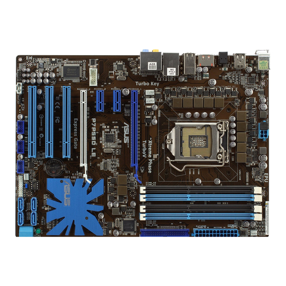
Motherboard overview 1.2.1 Motherboard layout Ensure that you install the motherboard into the chassis in the correct orientation. The edge with external ports goes to the rear part of the chassis. Place this side towards the rear of the chassis. Place six screws into the holes indicated by circles to secure the motherboard to the chassis. -
Page 15: Central Processing Unit (Cpu)
Contact your retailer immediately if the PnP cap is missing, or if you see any damage to the PnP cap/socket contacts/motherboard components. ASUS will shoulder the cost of repair only if the damage is shipment/ transit-related. - Page 16 Lift the load lever in the direction of the arrow until the load plate is completely lifted. Load plate Remove the PnP cap from the CPU socket. PnP cap Position the CPU over the socket, ensuring that the gold triangle is on the bottom-left corner of the socket, and then CPU notches fit the socket alignment keys into the CPU...
- Page 17 Close the load plate (A), and then push down the load lever (B), ensuring that the front edge of the load plate slides under the retention knob (C). Insert the load lever under the retention tab. ASUS P7P55D LE...
-
Page 18: Installing The Cpu Heatsink And Fan
1.3.2 Installing the CPU heatsink and fan ® The Intel LGA1156 processor requires a specially designed heatsink and fan assembly to ensure optimum thermal condition and performance. ® • When you buy a boxed Intel processor, the package includes the CPU fan and heatsink assembly. -
Page 19: Uninstalling The Cpu Heatsink And Fan
Rotate each fastener counterclockwise. Pull up two fasteners at a time in a diagonal sequence to disengage the heatsink and fan assembly from the motherboard. Carefully remove the heatsink and fan assembly from the motherboard. ASUS P7P55D LE... -
Page 20: System Memory
System memory 1.4.1 Overview The motherboard comes with four Double Data Rate 3 (DDR3) Dual Inline Memory Modules (DIMM) sockets. A DDR3 module has the same physical dimensions as a DDR2 DIMM but is notched differently to prevent installation on a DDR2 DIMM socket. DDR3 modules are developed for better performance with less power consumption. -
Page 21: Memory Configurations
To operate at the vendor-marked or at a higher frequency, refer to section Ai Tweaker menu for manual memory frequency adjustment. • For system stability, use a more efficient memory cooling system to support a full memory load (4 DIMMs) or overclocking condition. ASUS P7P55D LE... - Page 22 P7P55D LE Motherboard Qualified Vendors Lists (QVL) DDR3-1067MHz capability for CPU at 2.66, 2.8 and 2.93GHz DIMM socket Chip Timing support (Optional) Vendor Part No. Size Chip NO. Voltage Brand Lable(Bios) CORSAIR CM3X1024-1066C7 1024MB DS Heat-Sink Package • • •...
- Page 23 P7P55D LE Motherboard Qualified Vendors Lists (QVL) DDR3-1333MHz capability for CPU at 2.66, 2.8 and 2.93GHz (continued) DIMM socket support Timing Vendor Part No. Size Chip Brand Chip NO. Voltage (Optional) Dimm(Bios) Crucial CT25672BA1339.18FF 2048MB DS MICRON D9KPT(ECC) 9(1333-9-9-9-24) •...
- Page 24 P7P55D LE Motherboard Qualified Vendors Lists (QVL) DDR3-1600MHz capability for CPU at 2.66GHz DIMM socket support Chip Timing Vendor Part No. Size Chip NO. Voltage (Optional) Brand Dimm(Bios) A-DATA AD31600E001GMU 3072MB(Kit of 3) SS N/A Heat-Sink Package 8-8-8-24(1333-9-9-9-24) 1.65-1.85 •...
- Page 25 P7P55D LE Motherboard Qualified Vendors Lists (QVL) DDR3-1625MHz capability for CPU at 2.8 and 2.93GHz DIMM socket support Chip Timing Vendor Part No. Size SS/DS Chip NO. Voltage (Optional) Brand Lable(Bios) KINGSTON KHX13000D3LLK2/2GN(EPP) 2048MB(Kit of 2) Heat-Sink Package • •...
- Page 26 P7P55D LE Motherboard Qualified Vendors Lists (QVL) DDR3-1866MHz capability for CPU at 2.66GHz DIMM socket support Chip Timing Vendor Part No. Size Brand Chip NO. Voltage (Optional) Dimm(Bios) Apacer 78.0AGCQ.CBZ(XMP) 3GB(Kit of 3) Heat-Sink Package 9-9-9-27(1066-8-8-8-20) • Crucial BL12864BE2009.8SFB3(EPP) Heat-Sink Package 9-9-9-28(1333-9-9-9-24) •...
- Page 27 Hyper DIMM support is subject to the physical characteristics of individual CPUs. • According to Intel spec definition, DDR3-1600 is supported for one DIMM per channel only. ASUS exclusively provides two DDR3-1600 DIMM support for each memory channel. • According to Intel CPU spec, CPUs with a core frequency of 2.66G support the maximum DIMM frequency of up to DDR3-1333.
-
Page 28: Expansion Slot
Expansion slot In the future, you may need to install expansion cards. The following sub-sections describe the slot and the expansion cards that it supports. Unplug the power cord before adding or removing expansion cards. Failure to do so may cause you physical injury and damage motherboard components. -
Page 29: Jumpers
• Due to the chipset behavior, AC power off is required to enable C.P.R. function. You must turn off and on the power supply or unplug and plug the power cord before rebooting the system. ASUS P7P55D LE 1-17... -
Page 30: Memok! Switches
If the installed DIMMs still fail to boot after the whole tuning process, the DRAM_LED lights continuously. Replace the DIMMs with ones recommended in the Memory QVL (Qualified Vendors Lists) in this user manual or on the ASUS website at www.asus.com. -
Page 31: Connectors
Front Speaker Out Front Speaker Out Pink Mic In Mic In Mic In Mic In Orange – – Center/Subwoofer Center/Subwoofer Black – Rear Speaker Out Rear Speaker Out Rear Speaker Out Gray – – – Side Speaker Out ASUS P7P55D LE 1-19... -
Page 32: Internal Connectors
• Do not forget to connect the 8-pin EATX12V power plug. Otherwise, the system will not boot. • If you are uncertain about the minimum power supply requirement for your system, refer to the Recommended Power Supply Wattage Calculator at http://support.asus. com/PowerSupplyCalculator/PSCalculator.aspx?SLanguage=en-us for details. CPU, chassis, and power fan connectors (4-pin CPU_FAN, 4-pin CHA_FAN1, 3-pin CHA_FAN2, 3-pin PWR_FAN) The fan connectors support cooling fans of 350 mA~1000 mA (12 W max.) or a total... - Page 33 If you installed Serial ATA hard disk drives, you can create a RAID 0, 1, 5, and 10 ® ® configuration with the Intel Matrix Storage Technology through the onboard Intel chipset. ASUS P7P55D LE 1-21...
-
Page 34: System Panel Connector (20-8 Pin Panel)
• These connectors are set to Standard IDE mode by default. In Standard IDE mode, you can connect Serial ATA boot/data hard disk drives to these connectors. If you intend to create a Serial ATA RAID set using these connectors, set the Configure SATA as item in the BIOS to [RAID]. - Page 35 Never connect a 1394 cable to the USB connectors. Doing so will damage the motherboard! You can connect the front panel USB cable to the ASUS Q-Connector (USB, blue) first, and then install the Q-Connector (USB) to the USB connector onboard if your chassis supports front panel USB ports.
- Page 36 Digital audio connector (4-1 pin SPDIF_OUT) This connector is for an additional Sony/Philips Digital Interface (S/PDIF) port(s). Connect the S/PDIF Out module cable to this connector, then install the module to a slot opening at the back of the system chassis. The S/PDIF module is purchased separately.
- Page 37 This prevents incorrect insertion when you connect the IDE cable. • Use the 80-conductor IDE cable for Ultra DMA 133/100/66 IDE devices. If any device jumper is set as “Cable-Select”, ensure that all other device jumpers have the same setting. ASUS P7P55D LE 1-25...
-
Page 38: Installing An Operating System
The contents of the support DVD are subject to change at any time without notice. Visit the ASUS website at www.asus.com for updates. 1.10.1 Running the support DVD Place the support DVD into the optical drive. -
Page 39: Chapter 2: Bios Setup
BIOS in the future. Copy the original motherboard BIOS using the ASUS Update utility. 2.1.1 ASUS Update The ASUS Update is a utility that allows you to manage, save, and update the motherboard BIOS in Windows environment. ®... -
Page 40: Asus Ez Flash 2
Exit Menu for details. 2.1.2 ASUS EZ Flash 2 The ASUS EZ Flash 2 feature allows you to update the BIOS without using an OS-based utility. Before you start using this utility, download the latest BIOS file from the ASUS website at www.asus.com. -
Page 41: Asus Crashfree Bios 3 Utility
When the correct BIOS file is found, EZ Flash 2 performs the BIOS update process and automatically reboots the system when done. • Only a USB flash disk with FAT 32/16 format and single partition can support the ASUS EZ Flash 2 utility. -
Page 42: Bios Setup Program
• The BIOS setup screens shown in this section are for reference purposes only, and may not exactly match what you see on your screen. • Visit the ASUS website at www.asus.com to download the latest BIOS file for this motherboard. -
Page 43: Sata 1-6
When set to [Auto], the data transfer from and to the device occurs in multiple sectors at a time if the device supports multi-sector transfer feature. [Disabled] When set to [Disabled], the data transfer from and to the device occurs one sector at a time. ASUS P7P55D LE... -
Page 44: Storage Configuration
PIO Mode [Auto] [Auto] Allows automatic selection of the PIO (Programmed input/output) modes, which correspond to different data transfer rates. [0] [1] [2] [3] [4] Set the PIO mode to Mode 0, 1, 2, 3, or 4. DMA Mode [Auto] DMA (Direct Memory Access) allows your computer to transfer data to and from the hardware devices installed with much less CPU overhead. -
Page 45: Ahci Configuration
AHCI Settings Some SATA CD/DVD in AHCI mode need to wait ready longer. SATA Port1 [Not Detected] SATA Port2 [Not Detected] SATA Port3 [Not Detected] SATA Port4 [Not Detected] SATA Port5 [Not Detected] SATA Port6 [Not Detected] ASUS P7P55D LE... -
Page 46: System Information
SATA Port1–6 [XXXX] Displays the status of auto-detection of SATA devices. BIOS SETUP UTILITY Main S e l e c t t h e t y p e o f SATA Port1 devices connected to Device :Not Detected the system. SATA Port1 [Auto] SMART Monitoring... -
Page 47: Ai Tweaker Menu
Scroll down to display the following items: PCH Voltage [Auto] DRAM DATA REF Voltage on CHA [Auto] DRAM DATA REF Voltage on CHB [Auto] *********************************************** Load-Line Calibration [Auto] CPU Spread Spectrum [Auto] PCIE Spread Spectrum [Auto] v02.61 (C)Copyright 1985-2009, American Megatrends, Inc. ASUS P7P55D LE... -
Page 48: Ai Overclock Tuner
2.4.1 Ai Overclock Tuner [Auto] Allows selection of CPU overclocking options to achieve desired CPU internal frequency. Select either one of the preset overclocking configuration options: Manual Allows you to individually set overclocking parameters. Auto Loads the optimal settings for the system. D.O.C.P Overclocks DRAM frequency by adjusting BCLK frequency. -
Page 49: Xtreme Phase Full Power Mode
DIMMs you install on the motherboard. 1st Information: 7-7-7-20-4-60-8-5-20 The values vary depending on your settings of the following sub-items: DRAM CAS# Latency [Auto] Configuration options: [Auto] [3 DRAM Clock] [4 DRAM Clock] – [10 DRAM Clock] [11 DRAM Clock] ASUS P7P55D LE 2-11... - Page 50 DRAM RAS# to CAS# Delay [Auto] Configuration options: [Auto] [3 DRAM Clock] [4 DRAM Clock] – [9 DRAM Clock] [15 DRAM Clock] DRAM RAS# PRE Time [Auto] Configuration options: [Auto] [3 DRAM Clock] [4 DRAM Clock] – [9 DRAM Clock] [15 DRAM Clock] DRAM RAS# ACT Time [Auto] Configuration options: [Auto] [3 DRAM Clock] [4 DRAM Clock] –...
-
Page 51: Cpu Differential Amplitude
Offset Sign [-] This item appears only when you set the Offset Voltage item to a value other than [Auto]. To offset the voltage by a positive value. [–] To offset the voltage by a negative value. ASUS P7P55D LE 2-13... -
Page 52: Imc Voltage
Fixed Voltage [Auto] This item appears only whne you set the CPU Voltage Mode item to [Manual] and allows you to set a fixed CPU voltage. The values range from 0.85V to 1.70V* with a 0.00625V interval. Refer to the CPU documentation before setting the CPU Vcore voltage. Setting a high VCore voltage may damage the CPU permanently, and setting a low VCore voltage may make the system unstable. -
Page 53: Load-Line Calibration
Automatic configuration. [Disabled] Enhances the BCLK overclocking ability. [Enabled] Sets to [Enabled] for EMI control. 2.4.19 PCIE Spread Spectrum [Auto] [Auto] Automatic configuration. [Disabled] Enhances the PCIE overclocking ability. [Enabled] Sets to [Enabled] for EMI control. ASUS P7P55D LE 2-15... -
Page 54: Advanced Menu
Advanced menu The Advanced menu items allow you to change the settings for the CPU and other system devices. Be cautious when changing the settings of the Advanced menu items. Incorrect field values can cause the system to malfunction. BIOS SETUP UTILITY Main Ai Tweaker Advanced... - Page 55 Enables the No-Execution Page Protection Technology. [Disabled] Forces the XD feature flag to always return to zero (0). Intel(R) HT Technology [Enabled] [Enabled] Enables the Intel Hyper-Threading Technology. [Disabled] Only one thread per activated CPU core is enabled. ASUS P7P55D LE 2-17...
-
Page 56: North Bridge Configuration
Active Processor Cores [All] [All] Activate all CPU cores in the processor package. Activate only 1 CPU core in the processor package. Activate 2 CPU cores in the processor package. A20M [Disabled] [Enabled] Legacy OSes and APs may need this function enabled. [Disabled] Disables this function. -
Page 57: Onboard Devices Configuration
Serial ATA features that increases storage performance on random workloads by allowing the drive to internally optimize the order of commands. Serial Port1 Address [3F8/IRQ4] Allows you to select the Serial Port1 base address. Configuration options: [Disabled] [3F8/IRQ4] [2F8/IRQ3] [3E8/IRQ4] [2E8/IRQ3] ASUS P7P55D LE 2-19... -
Page 58: Usb Configuration
2.5.4 USB Configuration The items in this menu allows you to change the USB-related features. Select an item then press <Enter> to display the configuration options. BIOS SETUP UTILITY Advanced USB Configuration Options Module Version - 2.24.5-13.4 Disabled Enabled USB Devices Enabled: 2 Hubs USB Functions [Enabled]... -
Page 59: Pcipnp
[S1 (POS) only] Sets the APCI suspend mode to S1/POS (Power On Suspend). [S3 only] Sets the APCI suspend mode to S3/STR (Suspend To RAM). [Auto] The system automatically configures the ACPI suspend mode. ASUS P7P55D LE 2-21... -
Page 60: Eup Ready
2.6.2 Repost Video on S3 Resume [No] Determines whether to invoke VGA BIOS POST on S3/STR resume. [No] The system will not invoke VGA BIOS POST on S3/STR resume. [Yes] The system invokes VGA BIOS POST on S3/STR resume. 2.6.3 ACPI 2.0 Support [Disabled] [Disabled] When set to [Disabled], the system will not add additional tables as per... - Page 61 Power On By PS/2 Mouse [Disabled] [Disabled] Disables the Power On by a PS/2 mouse. [Enabled] Enables the Power On by a PS/2 mouse. This feature requires an ATX power supply that provides at least 1A on the +5VSB lead. ASUS P7P55D LE 2-23...
-
Page 62: Hardware Monitor
2.6.7 Hardware Monitor BIOS SETUP UTILITY Power Hardware Monitor CPU Temperature(PECI) CPU Temperature [35ºC/95ºF] MB Temperature [34ºC/93ºF] CPU Fan Speed [3590RPM] CPU Q-Fan Control [Disabled] Chassis Fan 1 Speed [N/A] Chassis Fan 2 Speed [N/A] Chassis Q-Fan Control [Disabled] Power Fan Speed [N/A] Voltage [ 1.224V]... -
Page 63: Boot Menu
These items specify the boot device priority sequence from the available devices. The number of device items that appears on the screen depends on the number of devices installed in the system. Configuration options: [Removable Dev.] [Hard Drive] [ATAPI CD-ROM] [Disabled] ASUS P7P55D LE 2-25... -
Page 64: Boot Settings Configuration
Disables the full screen logo display feature. [Enabled] Enables the full screen logo display feature. Set this item to [Enabled] to use the ASUS MyLogo 2™ feature. AddOn ROM Display Mode [Force BIOS] [Force BIOS] The third-party ROM messages will be forced to display during the boot sequence. -
Page 65: Change User Password
Select this item to clear the user password. Password Check [Setup] [Setup] BIOS checks for user password when accessing the Setup utility. [Always] BIOS checks for user password both when accessing Setup and booting the system. ASUS P7P55D LE 2-27... -
Page 66: Tools Menu
The Tools menu items allow you to configure options for special functions. Select an item then press <Enter> to display the submenu. 2.8.1 ASUS O.C. Profile This item allows you to store or load multiple BIOS settings. Add Your CMOS Profile Allows you to save the current BIOS file to the BIOS Flash. -
Page 67: Ai Net 2
(POST). 2.8.3 Express Gate [Auto] Allows you to enable or disable the ASUS Express Gate feature. The ASUS Express Gate feature is a unique instant-on environment that provides quick access to the Internet browser and Skype. Configuration options: [Disabled] [Enabled] [Auto] Enter OS Timer [10 Seconds] Sets countdown duration that the system waits at the Express Gate’s first... -
Page 68: Exit Menu
Exit menu The Exit menu items allow you to load the optimal or failsafe default values for the BIOS items, and save or discard your changes to the BIOS items. BIOS SETUP UTILITY Main Ai Tweaker Advanced Power Boot Tools Exit Exit Options Exit system setup...
Need help?
Do you have a question about the P7P55D LE and is the answer not in the manual?
Questions and answers
How to connet monitor to p7p55d mother board
The ASUS P7P55D LE motherboard does not have an integrated graphics output. To connect a monitor, you need to install a compatible graphics card into the PCI Express x16 slot and then connect the monitor to the video output ports on the graphics card.
This answer is automatically generated