
Related Manuals for ASROCK N68-VGS3 FX


Summary of Contents for ASROCK N68-VGS3 FX
-
Page 1: User Manual
N68-VGS3 FX / N68-VS3 FX User Manual Version 1.0 Published September 2011 Copyright©2011 ASRock INC. All rights reserved. 1 1 1 1 1... - Page 2 (including damages for loss of profits, loss of business, loss of data, interruption of business and the like), even if ASRock has been advised of the possibility of such damages arising from any defect or error in the manual or product.
-
Page 3: Table Of Contents
............Package Contents ..............5 Specifications ................6 Motherboard Layout (N68-VGS3 FX / N68-VS3 FX) ....11 I/O Panel (N68-VGS3 FX) ............12 I/O Panel (N68-VS3 FX) ............. 13 2 . 2 . 2 . 2 . 2 . Installation... - Page 4 3.4.7 USB Configuration ............45 Hardware Health Event Monitoring Screen ......... 46 Boot Screen ................47 3.6.1 Boot Settings Configuration ..........47 Security Screen ................. 48 Exit Screen ................49 4 . 4 . 4 . 4 . Software Support Software Support Software Support Software Support...
-
Page 5: Introduction Introduction
Introduction Introduction Introduction Thank you for purchasing ASRock N68-VGS3 FX / N68-VS3 FX motherboard, a reliable motherboard produced under ASRock’s consistently stringent quality control. It delivers excellent performance with robust design conforming to ASRock’s commitment to qual- ity and endurance. -
Page 6: Specifications
- Supports D-Sub with max. resolution up to 1920x1440 @ 60Hz - 5.1 CH HD Audio (VIA VT1705 Audio Codec) ® Audio - N68-VGS3 FX Realtek Giga PHY RTL8211CL, speed 10/100/1000 Mb/s - N68-VS3 FX Realtek PHY RTL8201EL, speed 10/100 Mb/s - Supports Wake-On-LAN - Supports PXE... - Page 7 Trial; ASRock MAGIX Multimedia Suite - OEM) - ASRock OC Tuner (see CAUTION 10) Unique Feature - ASRock Intelligent Energy Saver (see CAUTION 11) - ASRock Instant Boot - ASRock Instant Flash (see CAUTION 12) - ASRock OC DNA (see CAUTION 13)
- Page 8 ASRock UCC (Unlock CPU Core) feature simplifies AMD CPU activation. As long as a simple switch of the BIOS option “ASRock UCC”, you can unlock the extra CPU core to enjoy an instant performance boost. When UCC feature is enabled, the dual-core or triple-core CPU will boost to the quad-...
- Page 9 SATAII mode. You can also connect SATA hard disk to SATAII connector directly. 10. It is a user-friendly ASRock overclocking tool which allows you to surveil your system by hardware monitor function and overclock your hardware devices to get the best system performance under Windows ®...
- Page 10 - ASRock APP Charger. Simply installing the APP Charger driver, it makes your iPhone charged much quickly from your computer and up to 40% faster than before. ASRock APP Charger allows you to quickly charge many Apple devices simultaneously and even supports continuous charging when your PC enters into Standby mode (S1), Sus- pend to RAM (S3), hibernation mode (S4) or power off (S5).
-
Page 11: Motherboard Layout (N68-Vgs3 Fx / N68-Vs3 Fx)
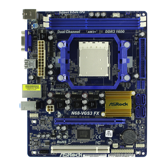
1.3 Motherboard L 1.3 Motherboard L 1.3 Motherboard Layout (N68- ayout (N68- ayout (N68-VGS3 FX / N68- ayout (N68- VGS3 FX / N68- VGS3 FX / N68-VS3 FX) VGS3 FX / N68- VS3 FX) VS3 FX) VS3 FX) 1.3 Motherboard L 1.3 Motherboard L... -
Page 12: I/O Panel (N68-Vgs3 Fx)
1 . 4 1 . 4 1 . 4 I/O P I/O P I/O Panel (N68- anel (N68- anel (N68- anel (N68-VGS3 FX) VGS3 FX) VGS3 FX) VGS3 FX) 1 . 4 1 . 4 I/O P I/O P anel (N68-... -
Page 13: I/O Panel (N68-Vs3 Fx)
1 . 5 1 . 5 1 . 5 I/O P I/O P I/O Panel (N68- anel (N68- anel (N68- anel (N68-VS3 FX) VS3 FX) VS3 FX) VS3 FX) 1 . 5 1 . 5 I/O P I/O P anel (N68- VS3 FX) PS/2 Mouse Port (Green) USB 2.0 Ports (USB01) -
Page 14: Installation
2. 2. 2. 2. 2. Installation Installation Installation Installation Installation This is a Micro ATX form factor (8.5-in x 7.0-in, 21.6 cm x 17.8 cm) motherboard. Before you install the motherboard, study the configuration of your chassis to en- sure that the motherboard fits into it. Pre-installation Precautions Pre-installation Precautions Pre-installation Precautions... -
Page 15: Cpu Installation
CPU Installation CPU Installation CPU Installation CPU Installation CPU Installation Step 1. Unlock the socket by lifting the lever up to a 90 angle. Step 2. Position the CPU directly above the socket such that the CPU corner with the golden triangle matches the socket corner with a small triangle. Step 3. -
Page 16: Installation Of Memory Modules (Dimm)
2.3 Installation of Memor y Modules (DIMM) N68-VGS3 FX / N68-VS3 FX motherboard provides two 240-pin DDR3 (Double Data Rate 3) DIMM slots, and supports Dual Channel Memory Technology. For dual channel configuration, you always need to install two identical (the same brand, speed, size and chip-type) memory modules in the DDR3 DIMM slots to activate Dual Channel Memory Technology. -
Page 17: Expansion Slots (Pci And Pci Express Slots)
2.4 Expansion Slots (PCI and PCI Express Slots) 2.4 Expansion Slots (PCI and PCI Express Slots) 2.4 Expansion Slots (PCI and PCI Express Slots) 2.4 Expansion Slots (PCI and PCI Express Slots) 2.4 Expansion Slots (PCI and PCI Express Slots) There are 1 PCI slot and 1 PCI Express slot on this motherboard. -
Page 18: Easy Multi Monitor Feature
2.5 Easy Multi Monitor Feature 2.5 Easy Multi Monitor Feature 2.5 Easy Multi Monitor Feature 2.5 Easy Multi Monitor Feature 2.5 Easy Multi Monitor Feature This motherboard supports Multi Monitor upgrade. With the internal onboard VGA and the external add-on PCI Express VGA card, you can easily enjoy the benefits of Multi Monitor feature. -
Page 19: Jumpers Setup
B. Click the items “This is my main monitor” and “Extend the desktop onto this monitor”. C. Click “OK” to save your change. D. Repeat steps A through C for the display icon identified by the number one, two and three. 6. -
Page 20: Onboard Headers And Connectors
after you update the BIOS. If you need to clear the CMOS when you just finish updating the BIOS, you must boot up the system first, and then shut it down before you do the clear-CMOS action. 2.7 Onboard Headers and Connectors 2.7 Onboard Headers and Connectors 2.7 Onboard Headers and Connectors 2.7 Onboard Headers and Connectors... -
Page 21: Front Panel Audio Header
USB 2.0 Headers Besides four default USB 2.0 USB_PWR ports on the I/O panel, there are (9-pin USB6_7) DUMMY two USB 2.0 headers on this (see p.11 No. 7) motherboard. Each USB 2.0 header can support two USB USB_PWR 2.0 ports. (9-pin USB4_5) USB_PWR (see p.11 No. - Page 22 System Panel Header This header accommodates PLED+ PLED- PWRBTN# several system front panel (9-pin PANEL1) functions. (see p.11 No. 16) DUMMY RESET# HDLED- HDLED+ Chassis Speaker Header Please connect the chassis speaker to this header. (4-pin SPEAKER 1) SPEAKER DUMMY (see p.11 No.
- Page 23 ATX 12V Power Connector Please note that it is necessary to connect a power supply with (4-pin ATX12V1) ATX 12V plug to this connector. (see p.11 No. 24) Failing to do so will cause power up failure. Serial port Header This COM1 header supports a RRXD1 DDTR#1...
-
Page 24: Sataii Hard Disk Setup Guide
2 . 8 2 . 8 2 . 8 SAT T T T T AII Hard Disk Setup Guide AII Hard Disk Setup Guide AII Hard Disk Setup Guide AII Hard Disk Setup Guide 2 . 8 2 . 8 AII Hard Disk Setup Guide Before installing SATAII hard disk to your computer, please carefully read below SATAII hard disk setup guide. -
Page 25: Serial Ata (Sata) / Serial Ataii (Sataii) Hard Disks
2 . 9 2 . 9 2 . 9 Serial A Serial A Serial AT T T T T A (SA A (SA A (SA A (SAT T T T T A) / Serial A A) / Serial A A) / Serial A A) / Serial AT T T T T AII (SA AII (SA AII (SA... -
Page 26: Sata / Sataii Hdd Hot Plug Feature And Operation Guide
SATA / SATAII Hot Plug support information of our motherboard is indicated in the product spec on our website: www.asrock.com 2. Make sure your SATA / SATAII HDD can support Hot Plug function from your dealer or HDD user manual. - Page 27 How to Hot Plug a SATA / SATAII HDD: Points of attention, before you process the Hot Plug: Please do follow below instruction sequence to process the Hot Plug, improper procedure will cause the SATA / SATAII HDD damage and data loss. Step 1 Step 2 Connect SATA data cable to...
-
Page 28: Driver Installation Guide
Support CD: .. \ RAID Installation Guide NOTE. For Windows 7 / 7 64-bit users, you do not need to load RAID driver from ASRock ® support CD. Please use the native driver to install Windows 7 / 7 64-bit OS, and then ®... -
Page 29: Untied Overclocking Technology
2 . 1 5 2 . 1 5 2 . 1 5 Untied Overclocking T Untied Overclocking T Untied Overclocking Technology Untied Overclocking T echnology echnology echnology 2 . 1 5 2 . 1 5 Untied Overclocking T echnology This motherboard supports Untied Overclocking Technology, which means during overclocking, FSB enjoys better margin due to fixed PCI / PCIE buses. -
Page 30: Etup Utility
3. 3. 3. 3. 3. BIOS SETUP UTILITY BIOS SETUP UTILITY BIOS SETUP UTILITY BIOS SETUP UTILITY BIOS SETUP UTILITY 3.1 Introduction 3.1 Introduction 3.1 Introduction 3.1 Introduction 3.1 Introduction This section explains how to use the BIOS SETUP UTILITY to configure your system. The SPI Memory on the motherboard stores the BIOS SETUP UTILITY. -
Page 31: Navigation Keys
Use [Enter], [TAB] System Time [ :00:09] or [SHIFT-TAB] to System Date [Tue 09/06/2011] select a field. : N68-VGS3 FX P1.00 BIOS Version Use [+] or [-] to Processor Type : AMD Athlon (tm) II X2 265 configure system Time. Processor (64bit) -
Page 32: Oc Tweaker Screen
Boot Failure Guard Count [Enabled] CPU/LDT Spread Spectrum [Enabled] PCIE Spread Spectrum [Enabled] SATA Spread Spectrum [Disabled] ASRock UCC AMD Turbo Core Technology [Auto] Select Screen [Enabled] AMD IO C-State Support Select Item CPU Active Core Control [Disabled] Enter Go to Sub Screen Processor Maximum Frequency x16.5 3300 MHZ... - Page 33 ASRock UCC ASRock UCC (Unlock CPU Core) feature simplifies AMD CPU activation. As long as a simple switch of the BIOS option “ASRock UCC”, you can unlock the extra CPU core to enjoy an instant performance boost. When UCC feature is...
- Page 34 Boot Failure Guard Count [Enabled] CPU/LDT Spread Spectrum [Enabled] PCIE Spread Spectrum [Enabled] SATA Spread Spectrum [Disabled] ASRock UCC AMD Turbo Core Technology [Auto] Select Screen AMD IO C-State Support [Enabled] Select Item CPU Active Core Control [Disabled] Enter Go to Sub Screen Processor Maximum Frequency x16.5 3300 MHZ...
- Page 35 Memory Timing BIOS SETUP UTILITY OC Tweaker Memory Timing [Disabled] Power Down Enable Bank Interleaving [Auto] Channel Interleaving [Hash 2] CAS Latency (CL) [Auto] [Auto] TRCD [Auto] TRAS [Auto] Command Rate [Auto] [Auto] Select Screen Select Screen TRTP [Auto] Select Item Select Item [Auto] Change Option...
- Page 36 TRRD Use this to adjust TRRD values. The default value is [Auto]. TWTR Use this to adjust TWTR values. The default value is [Auto]. TRTP Use this to adjust TRTP values. The default value is [Auto]. TFAW Use this to adjust TFAW values. The default value is [Auto]. Chipset Settings Chipset Voltage Use this to select chipset voltage.
-
Page 37: Advanced Screen
Setting wrong values in this section may cause the system to malfunction. ASRock Instant Flash ASRock Instant Flash is a BIOS flash utility embedded in Flash ROM. This convenient BIOS update tool allows you to update system BIOS without entering operating systems first like MS-DOS or Windows . -
Page 38: Cpu Configuration
3.4.1 3.4.1 CPU Configuration 3.4.1 CPU Configuration CPU Configuration CPU Configuration 3.4.1 3.4.1 CPU Configuration BIOS SETUP UTILITY Advanced CPU Configuration Enabling this function may reduce CPU voltage Cool ‘n’ Quiet [Auto] and memory freq., and Secure Virtual Machine [Enabled] lead to system Enhanced Halt State (C1E) [Disabled]... -
Page 39: Chipset Configuration
3 . 4 . 2 3 . 4 . 2 Chipset Configuration 3 . 4 . 2 Chipset Configuration Chipset Configuration Chipset Configuration 3 . 4 . 2 3 . 4 . 2 Chipset Configuration BIOS SETUP UTILITY Advanced Chipset Settings Auto/Enable/Disable Onboard HD Audio. -
Page 40: Acpi Configuration
3.4.3 3.4.3 3.4.3 ACPI Configuration ACPI Configuration ACPI Configuration 3.4.3 3.4.3 ACPI Configuration ACPI Configuration BIOS SETUP UTILITY Advanced ACPI Settings Select auto-detect or disable the STR feature. Suspend To RAM [Disabled] Away Mode Support [Disabled] Restore on AC / Power Loss [Power Off] Ring-In Power On [Disabled]... -
Page 41: Storage Configuration
3.4.4 3.4.4 Storage Configuration 3.4.4 Storage Configuration Storage Configuration Storage Configuration 3.4.4 3.4.4 Storage Configuration BIOS SETUP UTILITY Advanced Options Storage Configuration Disabled Enabled Onboard IDE Controller [Enabled] Onboard SATA Controller [Enabled] SATA Operation Mode [IDE] IDE1 Master [Hard Disk] [Not Detected] IDE1 Slave SATAII_1... - Page 42 TYPE Use this item to configure the type of the IDE device that you specify. Configuration options: [Not Installed], [Auto], [CD/DVD], and [ARMD]. [Not Installed]: Select [Not Installed] to disable the use of IDE device. [Auto]: Select [Auto] to automatically detect the hard disk drive. After selecting the hard disk information into BIOS, use a disk utility, such as FDISK, to partition and format the new IDE hard disk drives.
-
Page 43: Pcipnp Configuration
3.4.5 3.4.5 PCIPnP Configuration 3.4.5 PCIPnP Configuration PCIPnP Configuration PCIPnP Configuration 3.4.5 3.4.5 PCIPnP Configuration BIOS SETUP UTILITY Advanced Value in units of PCI Advanced PCI / PnP Settings clocks for PCI device latency timer [32] PCI Latency Timer register. PCI IDE BusMaster [Enabled] Select Screen... -
Page 44: Super Io Configuration
3.4.6 3.4.6 Super IO Configuration 3.4.6 Super IO Configuration Super IO Configuration Super IO Configuration 3.4.6 3.4.6 Super IO Configuration BIOS SETUP UTILITY Advanced Configure Super IO Chipset Allow BIOS to Enable or Disable Floppy Controller. Serial Port Address [3F8 / IRQ4] Parallel Port Address [378] Parallel Port Mode... -
Page 45: Usb Configuration
3.4.7 3.4.7 USB Configuration 3.4.7 USB Configuration USB Configuration USB Configuration 3.4.7 3.4.7 USB Configuration BIOS SETUP UTILITY Advanced USB Configuration To enable or disable the onboard USB controllers. [Enabled] USB Controller [Enabled] USB 2.0 Support Legacy USB Support [Enabled] USB Keyboard/Remote Power On [Disabled] USB Mouse Power On... -
Page 46: Hardware Health Event Monitoring Screen
3 . 5 3 . 5 3 . 5 Hardware Health Event Monitoring Screen Hardware Health Event Monitoring Screen Hardware Health Event Monitoring Screen 3 . 5 3 . 5 Hardware Health Event Monitoring Screen Hardware Health Event Monitoring Screen In this section, it allows you to monitor the status of the hardware on your system, including the parameters of the CPU temperature, motherboard temperature, CPU fan speed, chassis fan speed, and the critical voltage. -
Page 47: Boot Screen
Boot Screen Boot Screen Boot Screen Boot Screen Boot Screen In this section, it will display the available devices on your system for you to config- ure the boot settings and the boot priority. BIOS SETUP UTILITY Main OC Tweaker Advanced H/W Monitor Boot... -
Page 48: Security Screen
3 . 7 3 . 7 3 . 7 Security Screen Security Screen Security Screen 3 . 7 3 . 7 Security Screen Security Screen In this section, you may set or change the supervisor/user password for the system. For the user password, you may also clear it. BIOS SETUP UTILITY Main OC Tweaker... -
Page 49: Exit Screen
3 . 8 3 . 8 3 . 8 Exit Screen Exit Screen Exit Screen Exit Screen 3 . 8 3 . 8 Exit Screen BIOS SETUP UTILITY Main OC Tweaker Advanced H/W Monitor Boot Security Exit Exit Options Exit system setup after saving the Save Changes and Exit changes. -
Page 50: Software Support Software Support
4.2.4 Contact Information Contact Information Contact Information Contact Information Contact Information If you need to contact ASRock or want to know more about ASRock, welcome to visit ASRock’s website at http://www.asrock.com; or you may contact your dealer for further information.
Need help?
Do you have a question about the N68-VGS3 FX and is the answer not in the manual?
Questions and answers