
Related Manuals for ASROCK N68C-GS FX


Summary of Contents for ASROCK N68C-GS FX
-
Page 1: User Manual
N68C-GS FX / N68C-S FX User Manual Version 1.0 Published December 2011 Copyright©2011 ASRock INC. All rights reserved. 1 1 1 1 1... - Page 2 (including damages for loss of profits, loss of business, loss of data, interruption of business and the like), even if ASRock has been advised of the possibility of such damages arising from any defect or error in the manual or product.
-
Page 3: Table Of Contents
............5 5 5 5 5 Introduction ............Package Contents ..............5 Specifications ................6 Motherboard Layout (N68C-GS FX / N68C-S FX) ....... 12 I/O Panel (N68C-GS FX) ............13 I/O Panel (N68C-S FX) ............... 14 2 . 2 . 2 . 2 . Installation... - Page 4 3.4.3 ACPI Configuration ............43 3.4.4 Storage Configuration ............44 3.4.5 PCIPnP Configuration ............46 3.4.6 Floppy Configuration ............47 3.4.7 Super IO Configuration ............ 47 3.4.8 USB Configuration ............49 Hardware Health Event Monitoring Screen ......... 50 Boot Screen ................51 3.6.1 Boot Settings Configuration ..........
-
Page 5: Introduction Introduction
Introduction Introduction Introduction Thank you for purchasing ASRock N68C-GS FX / N68C-S FX motherboard, a reliable motherboard produced under ASRock’s consistently stringent quality control. It delivers excellent performance with robust design conforming to ASRock’s commitment to qual- ity and endurance. -
Page 6: Specifications
@ 60Hz - 5.1 CH HD Audio (VIA VT1705 Audio Codec) ® Audio - N68C-GS FX Realtek Giga PHY RTL8211CL, speed 10/100/1000 Mb/s - N68C-S FX Realtek PHY RTL8201EL, speed 10/100 Mb/s - Supports Wake-On-LAN 6 6 6 6 6... - Page 7 Trial; ASRock MAGIX Multimedia Suite - OEM) Unique Feature - ASRock OC Tuner (see CAUTION 10) - ASRock Intelligent Energy Saver (see CAUTION 11) - ASRock Instant Boot - ASRock Instant Flash (see CAUTION 12) - ASRock OC DNA (see CAUTION 13)
- Page 8 XP / XP 64-bit compliant - FCC, CE, WHQL Certifications * For detailed product information, please visit our website: http://www.asrock.com WARNING Please realize that there is a certain risk involved with overclocking, including adjusting the setting in the BIOS, applying Untied Overclocking Technology, or using the third- party overclocking tools.
- Page 9 UCC (Unlock CPU Core) feature simplifies AMD CPU activation. As long as a simple switch of the BIOS option “ASrock UCC”, you can unlock the extra CPU core to enjoy an instant performance boost. When UCC feature is enabled, the dual-core or triple-core CPU will boost to the quad-core CPU,...
- Page 10 Intelligent Energy Saver. ASRock website: http://www.asrock.com 12. ASRock Instant Flash is a BIOS flash utility embedded in Flash ROM. This convenient BIOS update tool allows you to update system BIOS without entering operating systems first like MS-DOS or Windows ®...
- Page 11 IE8. ASRock website: http://www.asrock.com/Feature/SmartView/index.asp 16. ASRock XFast USB can boost USB storage device performance. The performance may depend on the property of the device. 17. ASRock XFast LAN provides a faster internet access, which includes below benefits.
-
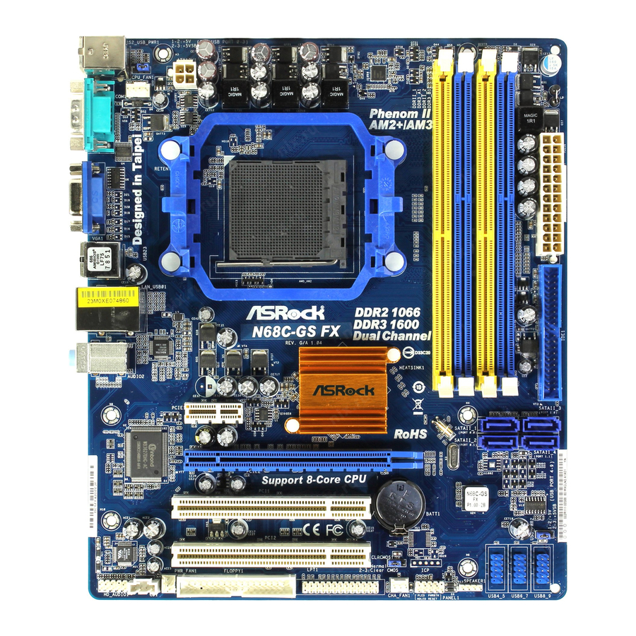
Page 12: Motherboard Layout
1.3 Motherboard L 1.3 Motherboard Layout (N68C 1.3 Motherboard L ayout (N68C ayout (N68C ayout (N68C- - - - - GS FX / N68C GS FX / N68C GS FX / N68C GS FX / N68C-S FX) -S FX) -S FX) -S FX) 1.3 Motherboard L 1.3 Motherboard L... -
Page 13: I/O Panel (N68C-Gs Fx)
1 . 4 1 . 4 1 . 4 I/O P I/O P I/O Panel (N68C anel (N68C anel (N68C anel (N68C - - - - - GS FX) GS FX) GS FX) GS FX) 1 . 4 1 . 4 I/O P I/O P anel (N68C... -
Page 14: I/O Panel (N68C-S Fx)
1 . 5 1 . 5 1 . 5 I/O P I/O P I/O Panel (N68C anel (N68C anel (N68C anel (N68C-S FX) -S FX) -S FX) -S FX) 1 . 5 1 . 5 I/O P I/O P anel (N68C -S FX) PS/2 Mouse Port (Green) USB 2.0 Ports (USB01) -
Page 15: Installation Installation
2. 2. 2. 2. 2. Installation Installation Installation Installation Installation This is a Micro ATX form factor (9.6-in x 8.2-in, 24.4 cm x 20.8 cm) motherboard. Before you install the motherboard, study the configuration of your chassis to en- sure that the motherboard fits into it. Pre-installation Precautions Pre-installation Precautions Pre-installation Precautions... -
Page 16: Cpu Installation
CPU Installation CPU Installation CPU Installation CPU Installation CPU Installation Step 1. Unlock the socket by lifting the lever up to a 90 angle. Step 2. Position the CPU directly above the socket such that the CPU corner with the golden triangle matches the socket corner with a small triangle. Step 3. -
Page 17: Installation Of Memory Modules (Dimm)
2.3 Installation of Memory Modules (DIMM) 2.3 Installation of Memory Modules (DIMM) 2.3 Installation of Memory Modules (DIMM) 2.3 Installation of Memory Modules (DIMM) 2.3 Installation of Memory Modules (DIMM) This motherboard provides two 240-pin DDR2 (Double Data Rate 2) DIMM slots and two 240-pin DDR3 (Double Data Rate 3) DIMM slots, and supports Dual Channel Memory Technology. - Page 18 Installing a DIMM Installing a DIMM Installing a DIMM Installing a DIMM Installing a DIMM Please make sure to disconnect power supply before adding or removing DIMMs or the system components. Step 1. Unlock a DIMM slot by pressing the retaining clips outward. Step 2.
-
Page 19: Expansion Slots (Pci And Pci Express Slots)
2.4 Expansion Slots (PCI and PCI Express Slots) 2.4 Expansion Slots (PCI and PCI Express Slots) 2.4 Expansion Slots (PCI and PCI Express Slots) 2.4 Expansion Slots (PCI and PCI Express Slots) 2.4 Expansion Slots (PCI and PCI Express Slots) There are 2 PCI slots and 2 PCI Express slots on this motherboard. -
Page 20: Easy Multi Monitor Feature
2.5 Easy Multi Monitor Feature 2.5 Easy Multi Monitor Feature 2.5 Easy Multi Monitor Feature 2.5 Easy Multi Monitor Feature 2.5 Easy Multi Monitor Feature This motherboard supports Multi Monitor upgrade. With the internal onboard VGA and the external add-on PCI Express VGA card, you can easily enjoy the benefits of Multi Monitor feature. -
Page 21: Jumpers Setup
B. Click the items “This is my main monitor” and “Extend the desktop onto this monitor”. C. Click “OK” to save your change. D. Repeat steps A through C for the display icon identified by the number one, two and three. 6. -
Page 22: Onboard Headers And Connectors
after you update the BIOS. If you need to clear the CMOS when you just finish updating the BIOS, you must boot up the system first, and then shut it down before you do the clear-CMOS action. 2.7 Onboard Headers and Connectors 2.7 Onboard Headers and Connectors 2.7 Onboard Headers and Connectors 2.7 Onboard Headers and Connectors... - Page 23 USB_PWR USB 2.0 Headers Besides four default USB 2.0 ports on the I/O panel, there are (9-pin USB8_9) DUMMY three USB 2.0 headers on this (see p.12 No. 16) motherboard. Each USB 2.0 header can support two USB USB_PWR 2.0 ports. USB_PWR (9-pin USB6_7) (see p.12 No.
- Page 24 C. Connect Ground (GND) to Ground (GND). D. MIC_RET and OUT_RET are for HD audio panel only. You don’t need to connect them for AC’97 audio panel. System Panel Header This header accommodates PLED+ PLED- several system front panel PWRBTN# (9-pin PANEL1) functions.
- Page 25 Though this motherboard provides 24-pin ATX power connector, it can still work if you adopt a traditional 20-pin ATX power supply. To use the 20-pin ATX power supply, please plug your power supply along with Pin 1 and Pin 13. 20-Pin ATX Power Supply Installation ATX 12V Power Connector Please note that it is necessary...
-
Page 26: Sataii Hard Disk Setup Guide
2 . 8 2 . 8 2 . 8 SAT T T T T AII Hard Disk Setup Guide AII Hard Disk Setup Guide AII Hard Disk Setup Guide AII Hard Disk Setup Guide 2 . 8 2 . 8 AII Hard Disk Setup Guide Before installing SATAII hard disk to your computer, please carefully read below SATAII hard disk setup guide. -
Page 27: Serial Ata (Sata) / Serial Ataii (Sataii) Hard Disks
2 . 9 2 . 9 2 . 9 Serial A Serial A Serial AT T T T T A (SA A (SA A (SA A (SAT T T T T A) / Serial A A) / Serial A A) / Serial A A) / Serial AT T T T T AII (SA AII (SA AII (SA... -
Page 28: Sata / Sataii Hdd Hot Plug Feature And Operation Guide
SATA / SATAII Hot Plug support information of our motherboard is indicated in the product spec on our website: www.asrock.com 2. Make sure your SATA / SATAII HDD can support Hot Plug function from your dealer or HDD user manual. - Page 29 How to Hot Plug a SATA / SATAII HDD: Points of attention, before you process the Hot Plug: Please do follow below instruction sequence to process the Hot Plug, improper procedure will cause the SATA / SATAII HDD damage and data loss. Step 1 Step 2 Connect SATA data cable to...
-
Page 30: Driver Installation Guide
B. Set the “SATA Operation Mode” option to [IDE]. STEP 2: Make a SATA / SATAII Driver Diskette. A. Insert the ASRock Support CD into your optical drive to boot your system. B. During POST at the beginning of system boot-up, press <F11> key, and then a window for boot devices selection appears. -
Page 31: Installing Windows ® 7 / 7 64-Bit / Vista
D. Then you will see these messages, Please insert a blank formatted diskette into floppy drive A: press any key to start Please insert a floppy diskette into the floppy drive, and press any key. E. The system will start to format the floppy diskette and copy SATA / SATAII drivers into the floppy diskette. -
Page 32: Untied Overclocking Technology
Support CD: .. \ RAID Installation Guide NOTE. For Windows 7 / 7 64-bit users, you do not need to load RAID driver from ASRock ® support CD. Please use the native driver to install Windows 7 / 7 64-bit OS, and then ®... -
Page 33: Etup Utility
3. 3. 3. 3. 3. BIOS SETUP UTILITY BIOS SETUP UTILITY BIOS SETUP UTILITY BIOS SETUP UTILITY BIOS SETUP UTILITY 3.1 Introduction 3.1 Introduction 3.1 Introduction 3.1 Introduction 3.1 Introduction This section explains how to use the BIOS SETUP UTILITY to configure your system. The SPI Memory on the motherboard stores the BIOS SETUP UTILITY. -
Page 34: Navigation Keys
Use [Enter], [TAB] System Time [ :00:09] or [SHIFT-TAB] to System Date [Thu 12/15/2011] select a field. : N68C-GS FX P1.00 BIOS Version Use [+] or [-] to Processor Type : AMD Phenom (tm) II X4 910e configure system Time. Processor (64bit) -
Page 35: Oc Tweaker Screen
Boot Failure Guard Count [Enabled] CPU/LDT Spread Spectrum [Enabled] PCIE Spread Spectrum [Enabled] SATA Spread Spectrum ASRock UCC [Disabled] [Auto] AMD Turbo Core Technology Select Screen AMD IO C-State Support [Enabled] Select Item CPU Active Core Control [Disabled] Enter Go to Sub Screen Processor Maximum Frequency x16.5 3300 MHZ... - Page 36 ASRock UCC ASRock UCC (Unlock CPU Core) feature simplifies AMD CPU activation. As long as a simple switch of the BIOS option “ASRock UCC”, you can unlock the extra CPU core to enjoy an instant performance boost. When UCC feature is...
- Page 37 Boot Failure Guard Count [Enabled] CPU/LDT Spread Spectrum [Enabled] PCIE Spread Spectrum [Enabled] SATA Spread Spectrum [Disabled] ASRock UCC AMD Turbo Core Technology [Auto] Select Screen AMD IO C-State Support [Enabled] Select Item CPU Active Core Control [Disabled] Enter Go to Sub Screen Processor Maximum Frequency x16.5 3300 MHZ...
- Page 38 Memory Timing BIOS SETUP UTILITY OC Tweaker Memory Timing [Unganged] Memory Controller Mode [Disabled] Power Down Enable Bank Interleaving [Auto] Channel Interleaving [Auto] CAS Latency (CL) [Auto] TRCD [Auto] [Auto] TRAS [Auto] Command Rate [Auto] Select Screen Select Screen [Auto] Select Item Select Item [Auto]...
- Page 39 Use this to adjust TWR values. The default value is [Auto]. TRFC Use this to adjust TRFC values. The default value is [Auto]. TRRD Use this to adjust TRRD values. The default value is [Auto]. TWTR Use this to adjust TWTR values. The default value is [Auto]. TRTP Use this to adjust TRTP values.
-
Page 40: Advanced Screen
Setting wrong values in this section may cause the system to malfunction. ASRock Instant Flash ASRock Instant Flash is a BIOS flash utility embedded in Flash ROM. This convenient BIOS update tool allows you to update system BIOS without entering operating systems first like MS-DOS or Windows . -
Page 41: Cpu Configuration
AM2 Boost This option appears only when you adopt AM2 CPU. If you set this option to [Enabled], you will enable ASRock AM2 Boost function, which will improve the memory performance. The default value is [Disabled]. Please refer to caution 20 on page 11 for details. -
Page 42: Chipset Configuration
3 . 4 . 2 3 . 4 . 2 Chipset Configuration 3 . 4 . 2 Chipset Configuration Chipset Configuration Chipset Configuration 3 . 4 . 2 3 . 4 . 2 Chipset Configuration BIOS SETUP UTILITY Advanced Chipset Settings Auto/Enable/Disable Onboard HD Audio. -
Page 43: Acpi Configuration
3 . 4 . 3 3 . 4 . 3 ACPI Configuration 3 . 4 . 3 ACPI Configuration ACPI Configuration ACPI Configuration 3 . 4 . 3 3 . 4 . 3 ACPI Configuration BIOS SETUP UTILITY Advanced ACPI Settings Select auto-detect or disable the STR feature. -
Page 44: Storage Configuration
3.4.4 3.4.4 Storage Configuration 3.4.4 Storage Configuration Storage Configuration Storage Configuration 3.4.4 3.4.4 Storage Configuration BIOS SETUP UTILITY Advanced Options Storage Configuration Disabled Enabled Onboard IDE Controller [Enabled] Onboard SATA Controller [Enabled] SATA Operation Mode [IDE] IDE1 Master [Hard Disk] [Not Detected] IDE1 Slave SATAII_1... - Page 45 TYPE Use this item to configure the type of the IDE device that you specify. Configuration options: [Not Installed], [Auto], [CD/DVD], and [ARMD]. [Not Installed]: Select [Not Installed] to disable the use of IDE device. [Auto]: Select [Auto] to automatically detect the hard disk drive. After selecting the hard disk information into BIOS, use a disk utility, such as FDISK, to partition and format the new IDE hard disk drives.
-
Page 46: Pcipnp Configuration
3.4.5 3.4.5 PCIPnP Configuration 3.4.5 PCIPnP Configuration PCIPnP Configuration PCIPnP Configuration 3.4.5 3.4.5 PCIPnP Configuration BIOS SETUP UTILITY Advanced Value in units of PCI Advanced PCI / PnP Settings clocks for PCI device latency timer [32] PCI Latency Timer register. PCI IDE BusMaster [Enabled] Select Screen... -
Page 47: Floppy Configuration
3 . 4 . 6 3 . 4 . 6 Floppy Configuration 3 . 4 . 6 Floppy Configuration Floppy Configuration Floppy Configuration 3 . 4 . 6 3 . 4 . 6 Floppy Configuration In this section, you may configure the type of your floppy drive. BIOS SETUP UTILITY Advanced Floppy Configuration... - Page 48 Parallel Port Mode Use this item to set the operation mode of the parallel port. The default value is [ECP+EPP]. If this option is set to [ECP+EPP], it will show the EPP version in the following item, “EPP Version”. Configuration options: [Normal], [Bi-Directional], and [ECP+EPP].
-
Page 49: Usb Configuration
3 . 4 . 8 3 . 4 . 8 USB Configuration 3 . 4 . 8 USB Configuration USB Configuration USB Configuration 3 . 4 . 8 3 . 4 . 8 USB Configuration BIOS SETUP UTILITY Advanced USB Configuration To enable or disable the onboard USB controllers. -
Page 50: Hardware Health Event Monitoring Screen
3 . 5 3 . 5 3 . 5 Hardware Health Event Monitoring Screen Hardware Health Event Monitoring Screen Hardware Health Event Monitoring Screen 3 . 5 3 . 5 Hardware Health Event Monitoring Screen Hardware Health Event Monitoring Screen In this section, it allows you to monitor the status of the hardware on your system, including the parameters of the CPU temperature, motherboard temperature, CPU fan speed, chassis fan speed, and the critical voltage. -
Page 51: Boot Screen
Boot Screen Boot Screen Boot Screen Boot Screen Boot Screen In this section, it will display the available devices on your system for you to config- ure the boot settings and the boot priority. BIOS SETUP UTILITY Main OC Tweaker Advanced H/W Monitor Boot... -
Page 52: Security Screen
3 . 7 3 . 7 3 . 7 Security Screen Security Screen Security Screen 3 . 7 3 . 7 Security Screen Security Screen In this section, you may set or change the supervisor/user password for the system. For the user password, you may also clear it. BIOS SETUP UTILITY Main OC Tweaker... -
Page 53: Exit Screen
3 . 8 3 . 8 3 . 8 Exit Screen Exit Screen Exit Screen Exit Screen 3 . 8 3 . 8 Exit Screen BIOS SETUP UTILITY Main OC Tweaker Advanced H/W Monitor Boot Security Exit Exit Options Exit system setup after saving the Save Changes and Exit changes. -
Page 54: Software Support Software Support
4.2.4 Contact Information Contact Information Contact Information Contact Information Contact Information If you need to contact ASRock or want to know more about ASRock, welcome to visit ASRock’s website at http://www.asrock.com; or you may contact your dealer for further information.
Need help?
Do you have a question about the N68C-GS FX and is the answer not in the manual?
Questions and answers