ASROCK N68-VGS3 UCC User Manual
Hide thumbs
Also See for N68-VGS3 UCC:
- Manual (146 pages) ,
- Datasheet (6 pages) ,
- User manual (50 pages)

Related Manuals for ASROCK N68-VGS3 UCC


Summary of Contents for ASROCK N68-VGS3 UCC
- Page 1 N68-VGS3 UCC / N68-VS3 UCC User Manual Version 1.0 Published February 2011 Copyright©2011 ASRock INC. All rights reserved. 1 1 1 1 1...
- Page 2 (including damages for loss of profits, loss of business, loss of data, interruption of business and the like), even if ASRock has been advised of the possibility of such damages arising from any defect or error in the manual or product.
-
Page 3: Table Of Contents
Serial ATA (SATA) / Serial ATAII (SATAII) Hard Disks Installation ................. 25 2.10 Hot Plug and Hot Swap Functions for SATA / SATAII HDDs ..25 2.11 SATA / SATAII HDD Hot Plug Feature and Operation Guide ..26 2.12 Driver Installation Guide ............28 2.13 Installing Windows... - Page 4 Hardware Health Event Monitoring Screen ......48 Boot Screen ................49 3.6.1 Boot Settings Configuration ........... 49 Security Screen ................ 50 Exit Screen ................51 4 . 4 . 4 . 4 . 4 . Software Support Software Support Software Support Software Support Software Support ...........
-
Page 5: Introduction Introduction
It delivers excellent performance with robust design conforming to ASRock’s com- mitment to quality and endurance. In this manual, chapter 1 and 2 contain introduction of the motherboard and step-by-step guide to the hardware installation. Chapter 3 and 4 contain the configuration guide to BIOS setup and information of the Support CD. -
Page 6: Specifications
Platform - Support for AM3 processors: AMD Phenom II X6 / X4 / X3 / X2 (except 920 / 940) / Athlon II X4 / X3 / X2 / Sempron processors (see CAUTION 1) - Supports Six-Core CPU - Supports UCC feature (Unlock CPU Core) (see CAUTION 2) - Supports AMD’s Cool ‘n’... - Page 7 - 1 x ATA133 IDE connector (supports 2 x IDE devices) - 1 x Print port header - 1 x COM port header - CPU/Chassis FAN connector - 24 pin ATX power connector - 4 pin 12V power connector - Front panel audio header - 2 x USB 2.0 headers (support 4 USB 2.0 ports)
- Page 8 Overclocking may affect your system stability, or even cause damage to the components and devices of your system. It should be done at your own risk and expense. We are not responsible for possible damage caused by overclocking.
- Page 9 Please be noted that the USB flash drive or hard drive must use FAT32/ 16/12 file system. 12. The software name itself – OC DNA literally tells you what it is capable of. OC DNA, an exclusive utility developed by ASRock, provides a conve- nient way for the user to record the OC settings and share with others.
- Page 10 14. If you desire a faster, less restricted way of charging your Apple devices, such as iPhone/iPod/iPad Touch, ASRock has prepared a wonderful solution for you - ASRock APP Charger. Simply installing the APP Charger driver, it makes your iPhone charged much quickly from your computer and up to 40% faster than before.
-
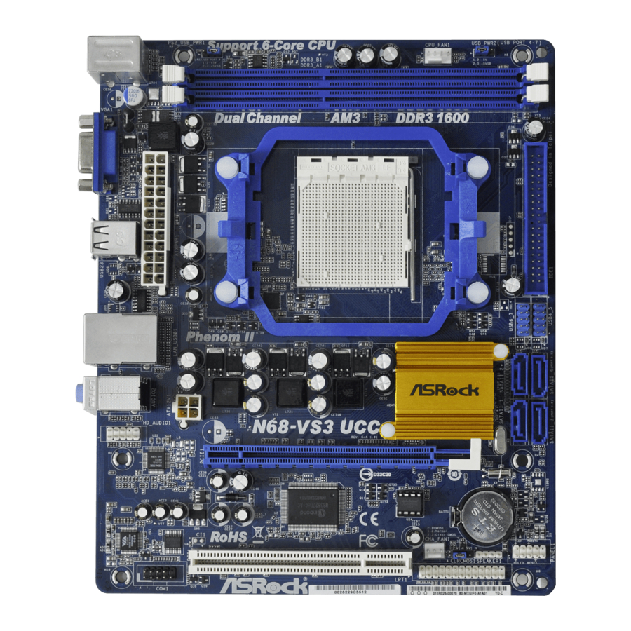
Page 11: Motherboard Layout (N68-Vgs3 Ucc / N68-Vs3 Ucc)
Clear CMOS Jumper (CLRCMOS1) CPU Fan Connector (CPU_FAN1) System Panel Header (PANEL1, White) USB_PWR2 Jumper Chassis Speaker Header 2 x 240-pin DDR3 DIMM Slots (SPEAKER 1, White) (Dual Channel: DDR3_A1, DDR3_B1; Blue) Print Port Header (LPT1, White) CPU Heatsink Retention Module... -
Page 12: I/O Panel (N68-Vgs3 Ucc)
Line In (Light Blue) VGA Port Front Speaker (Lime) PS/2 Keyboard Port (Purple) Microphone (Pink) * There are two LED next to the LAN port. Please refer to the table below for the LAN port LED indications. ACT/LINK SPEED LAN Port LED Indications... -
Page 13: I/O Panel (N68-Vs3 Ucc)
Line In (Light Blue) VGA Port Front Speaker (Lime) PS/2 Keyboard Port (Purple) Microphone (Pink) * There are two LED next to the LAN port. Please refer to the table below for the LAN port LED indications. ACT/LINK SPEED LAN Port LED Indications... -
Page 14: Installation
Installation Installation Installation This is a Micro ATX form factor (8.5-in x 7.0-in, 21.6 cm x 17.8 cm) motherboard. Before you install the motherboard, study the configuration of your chassis to en- sure that the motherboard fits into it. Pre-installation Precautions... -
Page 15: Cpu Installation
Step 4. When the CPU is in place, press it firmly on the socket while you push down the socket lever to secure the CPU. The lever clicks on the side tab to indicate that it is locked. -
Page 16: Installation Of Memory Modules (Dimm)
DIMMs or the system components. Step 1. Unlock a DIMM slot by pressing the retaining clips outward. Step 2. Align a DIMM on the slot such that the notch on the DIMM matches the break on the slot. notch break... -
Page 17: Expansion Slots (Pci And Pci Express Slots)
Step 2. Remove the bracket facing the slot that you intend to use. Keep the screws for later use. Step 3. Align the card connector with the slot and press firmly until the card is completely seated on the slot. -
Page 18: Easy Multi Monitor Feature
® to page 17 for proper expansion card installation procedures for details. 2. Connect the D-Sub monitor cable to the VGA/D-Sub port on the I/O panel of this motherboard. Connect another D-Sub monitor cable to the VGA/D-Sub connector of the add-on PCI Express VGA card. Connect the DVI-D monitor cable to the VGA/DVI-D connector of the add-on PCI Express VGA card. -
Page 19: Jumpers Setup
Clear CMOS (see p.11, No. 15) Note: CLRCMOS1 allows you to clear the data in CMOS. The data in CMOS includes system setup information such as system password, date, time, and system setup parameters. To clear and reset the system parameters to default setup, please turn off the computer and unplug the power cord from the power supply. -
Page 20: Onboard Headers And Connectors
BIOS. If you need to clear the CMOS when you just finish updating the BIOS, you must boot up the system first, and then shut it down before you do the clear-CMOS action. 2.7 Onboard Headers and Connectors 2.7 Onboard Headers and Connectors... -
Page 21: Front Panel Audio Header
HDA to function correctly. Please follow the instruction in our manual and chassis manual to install your system. 2. If you use AC’97 audio panel, please install it to the front panel audio header as below: A. - Page 22 Though this motherboard provides 4-Pin CPU fan (Quiet Fan) support, the 3-Pin CPU fan still can work successfully even without the fan speed control function. If you plan to connect the 3-Pin CPU fan to the CPU fan connector on this motherboard, please connect it to Pin 1-3.
- Page 23 Please note that it is necessary to connect a power supply with (4-pin ATX12V1) ATX 12V plug to this connector. (see p.11 No. 24) Failing to do so will cause power up failure. Serial port Header This COM1 header supports a RRXD1 DDTR#1 serial port module.
-
Page 24: Sataii Hard Disk Setup Guide
Before installing SATAII hard disk to your computer, please carefully read below SATAII hard disk setup guide. Some default setting of SATAII hard disks may not be at SATAII mode, which operate with the best performance. In order to enable SATAII function, please follow the below instruction with different vendors to correctly adjust your SATAII hard disk to SATAII mode in advance;... -
Page 25: Serial Ata (Sata) / Serial Ataii (Sataii) Hard Disks
STEP 2: Connect the SATA power cable to the SATA / SATAII hard disk. STEP 3: Connect one end of the SATA data cable to the motherboard’s SATAII connector. STEP 4: Connect the other end of the SATA data cable to the SATA / SATAII hard disk. 2 . 1 0 2 . -
Page 26: Sata / Sataii Hdd Hot Plug Feature And Operation Guide
SATA / SATAII driver is available on our support website: www.asrock.com 4. Make sure to use the SATA power cable & data cable, which are from our motherboard package. 5. Please follow below instructions step by step to reduce the risk of HDD crash... - Page 27 Please do follow below instruction sequence to process the Hot Unplug, improper procedure will cause the SATA / SATAII HDD damage and data loss. Step 1 Unplug SATA data cable from SATA / SATAII HDD side. Unplug SATA 15-pin power cable connector (Black) from SATA / SATAII HDD side. Step 2...
-
Page 28: Driver Installation Guide
(create, convert, delete, or rebuild) RAID functions on SATA / SATAII HDDs, you still need to set up “SATA Operation Mode” to [RAID] in BIOS first. Then, please set the RAID configuration by using the Windows RAID installation guide in the following path in the Support CD: .. -
Page 29: Untied Overclocking Technology
Untied Overclocking function, please enter “Overclock Mode” option of BIOS setup to set the selection from [Auto] to [CPU, PCIE, Async.]. Therefore, CPU FSB is untied during overclocking, but PCI / PCIE buses are in the fixed mode so that FSB can operate under a more stable overclocking environment. -
Page 30: Etup Utility
<Del> during the Power-On-Self-Test (POST) to enter the BIOS SETUP UTILITY, otherwise, POST will continue with its test routines. If you wish to enter the BIOS SETUP UTILITY after POST, restart the system by pressing <Ctl> + <Alt> + <Delete>, or by pressing the reset button on the system chassis. -
Page 31: Navigation Keys
To jump to the Exit Screen or exit the current screen <ESC> Main Screen Main Screen Main Screen Main Screen Main Screen When you enter the BIOS SETUP UTILITY, the Main screen will appear and display the system overview. N68-VGS3 UCC BIOS SETUP UTILITY OC Tweaker Advanced H/W Monitor... -
Page 32: Oc Tweaker Screen
(C) Copyright 1985-2005, American Megatrends, Inc. CPU Configuration Overclock Mode Use this to select Overclock Mode. The default value is [Auto]. Configura- tion options: [Auto], [CPU, PCIE, Sync.], [CPU, PCIE, Async.] and [Optimized]. CPU Frequency (MHz) Use this option to adjust CPU frequency. - Page 33 It will display Processor Maximum Voltage for reference. Multiplier/Voltage Change This item is set to [Auto] by default. If it is set to [Manual], you may adjust the value of Processor Frequency and Processor Voltage. However, it is recommended to keep the default value for system stability.
- Page 34 [Auto], [8 Bit] and [16 Bit]. Memory Configuration Memory Clock This item can be set by the code using [Auto]. You can set one of the standard values as listed: [400MHz DDR3_800], [533MHz DDR3_1066], [667MHz DDR3_1333] and [800MHz DDR3_1600].
- Page 35 [Auto] v02.54 (C) Copyright 1985-2003, American Megatrends, Inc. Memory Controller Mode This option appears only when you adopt Phenom CPU. It allows you to adjust the memory controller mode. Configuration options: [Unganged] and [Ganged]. The default value is [Unganged]. Power Down Enable Use this item to enable or disable DDR power down mode.
- Page 36 Use this to adjust values for CHA ADDR/CMD Setup feature. The default value is [Auto]. CHA CS/ODT Delay Use this to adjust values for CHA CS/ODT Delay feature. The default value is [Auto]. CHA CS/ODT Setup Use this to adjust values for CHB CS/ODT Setup feature. The default value is [Auto].
- Page 37 CHA CKE Drive Use this to adjust values for CHA CKE Drive. The default value is [Auto]. CHA CS/ODT Drive Use this to adjust values for CHA CS/ODT Drive. The default value is [Auto]. CHA ADDR/CMD Drive Use this to adjust values for CHA ADDR/CMD Drive. The default value is [Auto].
-
Page 38: Advanced Screen
. Just launch ® this tool and save the new BIOS file to your USB flash drive, floppy disk or hard drive, then you can update your BIOS only in a few clicks without preparing an additional floppy diskette or other complicated flash utility. -
Page 39: Cpu Configuration
® function, please set this item to [Enabled]. Please note that enabling this function may reduce CPU voltage and memory frequency, and lead to system stability or compatibility issue with some memory modules or power supplies. -
Page 40: Chipset Configuration
Primary Graphics Adapter This item will switch the PCI Bus scanning order while searching for video card. It allows you to select the type of Primary VGA in case of multiple video controllers. The default value of this feature is [PCI]. Configuration options: [PCI], [Onboard] and [PCI Express]. -
Page 41: Acpi Configuration
Use this item to enable or disable Ring-In signals to turn on the system from the power-soft-off mode. PCI Devices Power On Use this item to enable or disable PCI devices to turn on the system from the power-soft-off mode. PS/2 Keyboard Power On Use this item to enable or disable PS/2 keyboard to turn on the system from the power-soft-off mode. - Page 42 OSC Control Use this item to enable or disable OSC control. Configuration options: [Auto], [Enabled] and [Disabled]. The default value is [Auto].
-
Page 43: Storage Configuration
* If you select [RAID] mode, SATA / SATAII HDDs can not be accessed until you finish configuring RAID functions in NVIDIA BIOS / Windows RAID Utility. * If you install OS on SATA / SATAII HDDs, please do not change the setting of this item after OS installation. - Page 44 [ARMD]: This is used for IDE ARMD (ATAPI Removable Media Device), such as MO. LBA/Large Mode Use this item to select the LBA/Large mode for a hard disk > 512 MB under DOS and Windows; for Netware and UNIX user, select [Disabled] to disable the LBA/Large mode.
-
Page 45: Pcipnp Configuration
Setting wrong values in this section may cause the system to malfunction. PCI Latency Timer The default value is 32. It is recommended to keep the default value unless the installed PCI expansion cards’ specifications require other settings. PCI IDE BusMaster... -
Page 46: Super Io Configuration
(C) Copyright 1985-2003, American Megatrends, Inc. Serial Port Address Use this item to set the address for the onboard serial port or disable it. Configuration options: [Disabled], [3F8 / IRQ4], [2F8 / IRQ3], [3E8 / IRQ4], [2E8 / IRQ3]. -
Page 47: Usb Configuration
[Enabled] - Enables support for legacy USB. [Auto] - Enables legacy support if USB devices are connected. [Disabled] - USB devices are not allowed to use under legacy OS and BIOS setup when [Disabled] is selected. If you have USB compatibility issue, it is recommended to select [Disabled] to enter OS. -
Page 48: Hardware Health Event Monitoring Screen
(C) Copyright 1985-2003, American Megatrends, Inc. CPU Quiet Fan This item allows you to control the CPU fan speed and fan noise. If you set this option as [Disabled], the CPU fan will operate in full speed. If you set this option as [Enabled], you will find the items “Target CPU Temperature”... -
Page 49: Boot Screen
Boot Screen Boot Screen Boot Screen Boot Screen Boot Screen In this section, it will display the available devices on your system for you to config- ure the boot settings and the boot priority. BIOS SETUP UTILITY Main OC Tweaker... -
Page 50: Security Screen
Security Screen 3 . 7 3 . 7 Security Screen Security Screen In this section, you may set or change the supervisor/user password for the system. For the user password, you may also clear it. BIOS SETUP UTILITY Main OC Tweaker... -
Page 51: Exit Screen
When you select this option, it will pop-out the following message, “Dis- card changes?” Select [OK] to discard all changes. Load BIOS Defaults Load BIOS default values for all the setup questions. F9 key can be used for this operation. Load Performance Setup Default (IDE/SATA) This performance setup default may not be compatible with all system configurations. -
Page 52: Software Support Software Support
4.2.1 Running The Support CD 4.2.1 Running The Support CD To begin using the support CD, insert the CD into your CD-ROM drive. The CD automatically displays the Main Menu if “AUTORUN” is enabled in your computer. If the Main Menu did not appear automatically, locate and double click on the file “ASSETUP.EXE”...
Need help?
Do you have a question about the N68-VGS3 UCC and is the answer not in the manual?
Questions and answers