Table of Contents
Advertisement
Advertisement
Table of Contents

Related Manuals for Supero X8DAi


Summary of Contents for Supero X8DAi
- Page 1 UPER X8DA3 X8DAi (Preliminary Draft) USER’S MANUAL Revision 1.0...
- Page 2 Clara County in the State of California, USA. The State of California, County of Santa Clara shall be the exclusive venue for the resolution of any such disputes. Super Micro's total liability for all claims will not exceed the price paid for the hardware product.
-
Page 3: Preface
Preface Preface About This Manual This manual is written for system integrators, PC technicians and knowledgeable PC users. It provides information for the installation and use of the X8DA3/ X8DAi motherboard. The X8DA3/X8DAi supports the Intel Tylersburg-EP platform, the fi rst dual-processing platform that supports the Intel QuickPath Inter- connect Technology, providing the next generation point-to-point system interface, replacing the current Front Side Bus. -
Page 4: Table Of Contents
X8DA3/X8DAi User's Manual Table of Contents Preface About This Manual ................... iii Manual Organization ..................iii Conventions Used in the Manual ............... iii Chapter 1: Introduction 1-1 Overview ....................1-1 1-2 Checklist ....................1-1 Contacting Supermicro ................1-2 X8DA3/X8DAi Image ..............1-3 X8DA3/X8DAi Layout .............. - Page 5 Table of Contents Power Button ..................2-14 2-5 Connecting Cables ................2-15 ATX Power Connector ................2-15 Processor Power Connector ..............2-15 Universal Serial Bus (USB0/1) ..............2-16 Chassis Intrusion ..................2-16 Fan Headers ..................2-17 Keylock ..................... 2-17 ATX PS/2 Keyboard and Mouse Ports ............. 2-18 Serial Ports .....................
- Page 6 X8DA3/X8DAi User's Manual Before Power On ..................3-1 No Power ....................3-1 No Video ....................3-2 Losing the System’s Setup Confi guration ..........3-2 Memory Errors ................... 3-2 3-2 Technical Support Procedures ..............3-3 3-3 Frequently Asked Questions ..............3-3 3-4 Returning Merchandise for Service ............
-
Page 7: Chapter 1: Introduction
Chapter 1: Introduction Chapter 1 Introduction Overview Checklist Congratulations on purchasing your computer motherboard from an acknowledged leader in the industry. Supermicro boards are designed with the utmost attention to detail to provide you with the highest standards in quality and performance. Check that the following items have all been included with your motherboard. -
Page 8: Contacting Supermicro
X8DA3/X8DAi User's Manual Contacting Supermicro Headquarters Address: Super Micro Computer, Inc. 980 Rock Ave. San Jose, CA 95131 U.S.A. Tel: +1 (408) 503-8000 Fax: +1 (408) 503-8008 Email: marketing@supermicro.com (General Information) support@supermicro.com (Technical Support) Web Site: www.supermicro.com Europe Address: Super Micro Computer B.V. -
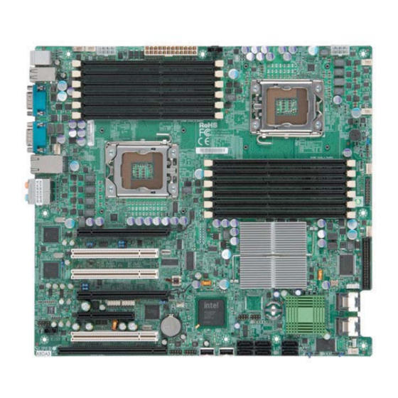
Page 9: X8Da3/X8Dai Image
Chapter 1: Introduction X8DA3/X8DAi Image Note: The drawings and pictures shown in this manual were based on the latest PCB Revision available at the time of publishing of the manual. The motherboard you’ve received may or may not look exactly the same as the graphics shown in the manual. - Page 10 X8DA3/X8DAi User's Manual X8DA3/X8DAi Motherboard Layout Fan5 Fan6 JPW1 JPW3 JPW2 P2 DIMM1A Fan1 P2 DIMM1B P2 DIMM2A P2 DIMM2B P2 DIMM3A CPU1 P2 DIMM3B Fan7/CPU1 X8DA3/i P1 DIMM3B CPU2 P1 DIMM3A P1 DIMM2B P1 DIMM2A P1 DIMM1B P1 DIMM1A...
-
Page 11: Quick Reference
Chapter 1: Introduction X8DA3/X8DAi Quick Reference Jumper Description Default Setting JBT1 CMOS Clear (See Section 5-10) C1/JI SMB to PCI-Express Slots 2-3 (Disabled) C3/JI SMB to PCI Slots 2-3 (Disabled) JPF1 1394_1/1394_2 Enable 1-2 (Normal) JPL1/JPL2 LAN1/2 Enable Pins 1-2 (Enabled) JPS1 SAS Enable Pins 1-2 (Enabled) -
Page 12: Motherboard Features
X8DA3/X8DAi User's Manual Motherboard Features • ® Two Intel Nehalem-EP (LGA 1336) processors, each processor supporting two full-width Intel QuickPath Interconnect links with a total of up to 51.2 GB/s Data Transfer Rate (6.4 GB/s per direction) Memory • Twelve 240-pin DIMM sockets support up to 96 GB of DDR3 Registered ECC Memory (See Section 2-3 in Chapter 2 for DIMM Slot Population.) - Page 13 Chapter 1: Introduction ACPI Features • Slow blinking LED for suspend state indicator • Main switch override mechanism • ACPI Power Management • Keyboard Wakeup from Soft-off Onboard I/O • Intel ICH9R supports six SATA2 ports (with RAID0, RAID1, RAID10, RAID5 supported in the Windows OS Environment) •...
- Page 14 X8DA3/X8DAi User's Manual PROCESSOR#1 PROCESSOR#2 Ports PCI-E x16 #3-6 IOH-36D TYLERSBURG PCI-Ex16 Ports #7-10 Ports #0~3 Ports PCI-Ex4 Port #1-2 LSI 1068 Ports #4~7 PCI-Ex4 LANES1/2 #4 #5 ICH9 PCI-Ex1 3.0 Gb/S PHY#1 LANE5 iI82573V 4 Rear PHY#2 PCI-Ex1 4 Front...
-
Page 15: Chipset Overview
Chapter 1: Introduction Chipset Overview Built upon the functionality and the capability of the Tylersburg-EP platform, the X8DA3/X8DAi motherboard provides the performance and feature set required for dual-processor-based high-end systems with confi guration options optimized for workstations, high-end CAD systems, and intensive applications. The Tylersburg- EP platform consists of the Nehalem-EP (LGA 1336) processor, the Tylersburg IOH (IOH-D36), and the South Bridge (ICH9R). -
Page 16: Special Features
X8DA3/X8DAi User's Manual Special Features Recovery from AC Power Loss BIOS provides a setting for you to determine how the system will respond when AC power is lost and then restored to the system. You can choose for the system to remain powered off (in which case you must hit the power switch to turn it back on) or for it to automatically return to a power- on state. -
Page 17: Acpi Features
Chapter 1: Introduction CPU Overheat LED and Control This feature is available when the user enables the CPU overheat warning func- tion in the BIOS. This allows the user to defi ne an overheat temperature. When the CPU temperature passes this threshold, both the overheat fan and the warning LED are triggered. -
Page 18: Power Supply
X8DA3/X8DAi User's Manual the system malfunctions and you want to turn off the power, just press and hold the power button for 4 seconds. This option can be set in the Power section of the BIOS Setup routine. Wake-On-LAN (WOL) Wake-On-LAN is defi... -
Page 19: Super I/O
Chapter 1: Introduction Super I/O The disk drive adapter functions of the Super I/O chip include a fl oppy disk drive controller that is compatible with industry standard 82077/765, a data separator, write pre-compensation circuitry, decode logic, data rate selection, a clock genera- tor, drive interface control logic and interrupt and DMA logic. - Page 20 X8DA3/X8DAi User's Manual Notes 1-14...
-
Page 21: Chapter 2: Installation
Chapter 2: Installation Chapter 2 Installation Static-Sensitive Devices Electrostatic Discharge (ESD) can damage electronic com ponents. To prevent dam- age to your system board, it is important to handle it very carefully. The following measures are generally suffi cient to protect your equipment from ESD. Precautions •... -
Page 22: Processor And Heatsink Installation
X8DA3/X8DAi User's Manual Processor and Heatsink Installation When handling the processor package, avoid placing direct pressure on the label area of the fan. Notes: Always connect the power cord last and always remove it before adding, re- moving or changing any hardware components. Make sure that you install the processor into the CPU socket before you install the CPU heatsink. - Page 23 Chapter 2: Installation Align CPU Pin1 (the CPU corner gold dot marked with a triangle) against the Socket Key socket corner marked with a triangle (Socket Notch) cutout. CPU Key (semi- circle cutout) Align the CPU key, the semi-circle below the circle. cutout below a gold dot, against the Pin 1 w/a Tri- socket key, which is the notch on...
- Page 24 X8DA3/X8DAi User's Manual Installing a CEK Heatsink CEK Passive Heatsink Do not apply any thermal grease to the heatsink or the CPU die because the required amount has already been applied. Place the heatsink on top of the CPU Screw#1...
- Page 25 Chapter 2: Installation 3. Once the CPU is loosened, remove Screw#1 the heatsink from the CPU socket. 4. Clean the surface of the CPU and the heatsink to get rid of the old thermal grease. Reapply the proper amount of thermal grease on the surface Screw#2 before you re-install the CPU and the heatsink.
-
Page 26: Memory Installation
X8DA3/X8DAi User's Manual Memory Installation Note: Check the Supermicro web site for recommended memory modules. CAUTION Exercise extreme care when installing or removing DIMM modules to prevent any possible damage. Also note that the memory is interleaved to improve performance (See step 1). -
Page 27: Memory Support
Chapter 2: Installation Memory Support The X8DA3/X8DAi supports up to 96 GB Registered ECC DDR3 1333 MHz/1066 MHz/800 MHz in 12 DIMMs. DIMM Module Population Confi guration For memory to work properly, follow the tables below for memory installation: DIMM Population Table DIMM DIMMs DIMM Type (Reg.=... - Page 28 X8DA3/X8DAi User's Manual Installing and Removing DIMMs DIMM DDR3 Notch Notch X8DA3/i Release Note: Notch Release should align with the receptive point on the slot To Install: Insert module vertically and press down until it snaps into place. Pay attention to the alignment notch at the bottom.
-
Page 29: Control Panel Connectors And Io Ports
Chapter 2: Installation Control Panel Connectors/IO Ports The I/O ports are color coded in conformance with the PC 99 specifi cation. See the picture below for the colors and locations of the various I/O ports. 1. Back Panel Connectors/IO Ports X8DA3/i Back Panel I/O Port Locations and Defi... -
Page 30: Front Control Panel
X8DA3/X8DAi User's Manual 2. Front Control Panel JF1 contains header pins for various buttons and indicators that are normally lo- cated on a control panel at the front of the chassis. These connectors are designed specifi cally for use with Supermicro server chassis. See the fi gure below for the descriptions of the various control panel buttons and LED indicators. -
Page 31: Front Control Panel Pin Defi Nitions
Chapter 2: Installation 3. Front Control Panel Pin Defi nitions NMI Button NMI Button The non-maskable interrupt button Pin Defi nitions (JF1) header is located on pins 19 and 20 Pin# Defi nition of JF1. Refer to the table on the right Control for pin defi... -
Page 32: Hdd Led
X8DA3/X8DAi User's Manual HDD LED The HDD LED connection is located HDD LED on pins 13 and 14 of JF1. Attach a Pin Defi nitions (JF1) hard drive LED cable here to display Pin# Defi nition disk activity (for any hard drive ac-... -
Page 33: Overheat/Fan Fail Led
Chapter 2: Installation Overheat (OH)/Fan Fail LED OH/Fan Fail LED Pin Defi nitions (JF1) Connect an LED Cable to the OH/Fan Pin# Defi nition Fail connection on pins 7 and 8 of JF1 to provide advanced warnings Ground of chassis overheating or fan failure. OH/Fan Fail Indicator Refer to the table on the right for pin Status... -
Page 34: Reset Button
X8DA3/X8DAi User's Manual Reset Button Reset Button The Reset Button connection is located Pin Defi nitions (JF1) on pins 3 and 4 of JF1. Attach it to a Pin# Defi nition hardware reset switch on the computer Reset case. Refer to the table on the right for Ground pin defi... -
Page 35: Connecting Cables
Chapter 2: Installation Connecting Cables ATX Power 24-pin Connector Pin Defi nitions Pin# Defi nition Pin # Defi nition ATX Power Connector +3.3V +3.3V There are a 24-pin main power sup- -12V +3.3V ply connector(JPW3) and two 8-pin CPU PWR connectors (JPW1/JPW2) PS_ON on the motherboard. -
Page 36: Universal Serial Bus (Usb0/1)
X8DA3/X8DAi User's Manual Universal Serial Bus (USB) Back Panel USB Front Panel USB (USB0/1/2/3) (USB8/9) There are ten USB 2.0 (Universal Pin# Defi nitions Pin# Defi nition Serial Bus) ports/headers on the motherboard. Back Panel USB Ports Data- 0/1/2/3 are located at JUSB1. The... -
Page 37: Fan Headers
Chapter 2: Installation Fan Headers Fan Header The X8DA3/X8DAi has six chassis/system fan Pin Defi nitions headers (Fan1 to Fan6) and two CPU fans Pin# Defi nition (Fan7/Fan8) on the motherboard. All these Ground 4-pin fans headers are backward compatible +12V with the traditional 3-pin fans. -
Page 38: Serial Ports
X8DA3/X8DAi User's Manual ATX PS/2 Keyboard and PS/2 PS/2 Keyboard and Mouse Port Pin Mouse Ports Defi nitions The ATX PS/2 keyboard and the PS/2 Pin# Defi nition mouse are located on the back panel. Data See the table on the right for pin defi - nitions. -
Page 39: Wake-On-Lan
Chapter 2: Installation Wake-On-LAN Wake-On-LAN Pin Defi nitions The Wake-On-LAN header is located Pin# Defi nition at JWOL1 on the motherboard. You +5V Standby must also have a LAN card with a Ground Wake-On-LAN connector and a cable Wake-up to use this feature. See the table on the right for pin defi... -
Page 40: Glan (Ethernet Ports)
X8DA3/X8DAi User's Manual GLAN 1/2 (Giga-bit Ethernet GLAN2 Ports) Two G-bit Ethernet ports are located on the I/O backplane. These ports accept RJ45 type cables. GLAN1 T-SGPIO Headers T-SGPIO Two SGPIO (Serial-Link General Pin Defi nitions Purpose Input/Output) headers (T- Pin# Defi... - Page 41 Chapter 2: Installation Power SMB (I C) Connector PWR SMB Pin Defi nitions Power System Management Bus Pin# Defi nition C) Connector (J6) monitors power Clock supply, fan and system temperatures. Data See the table on the right for pin PWR Fail defi...
-
Page 42: High Defi Nition Audio
X8DA3/X8DAi User's Manual High Defi nition Audio (HD Audio) Orange: This motherboard features a 7.1+2 Chan- Blue: Line-In CEN/LFE nel High Defi nition Audio (HDA) codecs that provide 10DAC channels, simultaneously sup- Black: Back Green:Front porting 7.1 sound playback with 2 channels... -
Page 43: Front Panel Audio
Chapter 2: Installation Front Panel Audio When front panel headphones are plugged in, the back panel audio output is dis- abled. This is done through the FP Audio header (JC2). If the front panel interface card is not connected to the front panel audio header, jumpers should be installed on the header (JC2) pin pairs: 1-2, 5-6, and 9-10. -
Page 44: Jumper Settings
X8DA3/X8DAi User's Manual Jumper Settings Explanation of Connector Jumpers Pins To modify the operation of the mother- board, jumpers can be used to choose Jumper between optional settings. Jumpers cre- ate shorts between two pins to change the function of the connector. Pin 1 is identifi... -
Page 45: Clear Cmos
Chapter 2: Installation CMOS Clear JBT1 is used to clear CMOS. Instead of pins, this "jumper" consists of contact pads to prevent the accidental clearing of CMOS. To clear CMOS, use a metal object such as a small screwdriver to touch both pads at the same time to short the connection. - Page 46 X8DA3/X8DAi User's Manual C Bus to PCI-Exp. Slots C to PCI-Exp Jumpers JI C1 and JI C2 allow you to Jumper Settings connect the System Management Bus Jumper Setting Defi nition C) to PCI-Express slots. The default Enabled setting is Open to disable the connec- Disabled (Default) tion.
-
Page 47: Sas Enable
Chapter 2: Installation SAS Enable/Disable SAS Enable Jumper Settings Jumper JPS1 allows you to enable or Jumper Setting Defi nition disable the onboard SAS connections. SAS Enabled (Default) The default setting is Pins 1-2 to enable SAS Disabled the connection. See the table on the right for jumper settings. -
Page 48: 1394_1/1394_2 Enable
X8DA3/X8DAi User's Manual 1394_1/1394_2 Enable 1394 Enable Jumper Settings Jumper JPF1 allows you to enable or Jumper Setting Defi nition disable 1394_1/1394_2. The default Normal (Default) setting is Pins 1-2 to enable the con- 1394 Disabled nection. See the table on the right for jumper settings. -
Page 49: Onboard Indicators
Chapter 2: Installation Onboard Indicators Activity L i n k GLAN LEDs Rear View (when facing the There are two GLAN ports on the moth- rear side of the chassis) erboard. Each Gigabit Ethernet LAN port GLAN Activity Indicator LED Settings has two LEDs. -
Page 50: Sas Led Indicators
X8DA3/X8DAi User's Manual SAS LED Indicators Onboard SAS LED Indicators Two Onboard SAS LED are located at (LES1/LES2) Settings LES1/LES2 on the motherboard. When LED Color Defi nition this LES1 is lit, SAS Connections 0~3 are LES1 SAS#0~3: Active active. When this LES2 is lit, SAS Con-... -
Page 51: Floppy Connector
Chapter 2: Installation Floppy Drive, SIMLP, Serial ATA and Hard Disk Drive Connections Note the following when connecting the fl oppy and hard disk drive cables: • The fl oppy disk drive cable has seven twisted wires. • A red mark on a wire typically designates the location of pin 1. •... -
Page 52: Serial Ata Ports
X8DA3/X8DAi User's Manual Serial ATA Ports Serial ATA Pin Defi nitions Six Serial ATA Ports (I-SATA0~I- Pin# Defi nition SATA 5) are located at JS1~JS6 Ground on the motherboard. These ports TX_P provide serial-link signal transmis- TX_N sion, which is faster than that of the Ground traditional Parallel ATA. -
Page 53: Chapter 3: Troubleshooting
Chapter 3: Troubleshooting Chapter 3 Troubleshooting Troubleshooting Procedures Use the following procedures to troubleshoot your system. If you have followed all of the procedures below and still need assistance, refer to the ‘Technical Support Procedures’ and/or ‘Returning Merchandise for Service’ section(s) in this chapter. Note: Always disconnect the power cord before adding, changing or installing any hardware components. -
Page 54: No Video
X8DA3/X8DAi User's Manual No Video If the power is on but you have no video, remove all the add-on cards and cables. Use the speaker to determine if any beep codes exist. Refer to the Appendix for details on beep codes. -
Page 55: Technical Support Procedures
Chapter 3: Troubleshooting Technical Support Procedures Before contacting Technical Support, please take the following steps. Also, please note that as a motherboard manufacturer, Supermicro does not sell directly to end- users, so it is best to fi rst check with your distributor or reseller for troubleshooting services. -
Page 56: Returning Merchandise For Service
X8DA3/X8DAi User's Manual Question: How do I update my BIOS? Answer: It is recommended that you do not upgrade your BIOS if you are not experiencing any problems with your system. Updated BIOS fi les are located on our web site at (http://www.supermicro.com/support/bios/). Please check our BIOS warning message and the information on how to update your BIOS on our web site. -
Page 57: Appendix A: Bios Post Error Codes
Appendix A: BIOS POST Error Codes Appendix A BIOS POST Error Codes This section lists the POST (Power On Self Test) codes for the AMI BIOS. POST codes are divided into two categories: recoverable and terminal. Recoverable POST Errors When a recoverable type of error occurs during POST, the BIOS will display an POST code that describes the problem. - Page 58 X8DA3/X8DAi User's Manual Notes...
-
Page 59: Appendix B: Installing The Windows Os
Appendix B: Installing the Windows OS Appendix B Installing the Windows OS After all hardware components have been installed, you must fi rst confi gure Intel South Bridge RAID Settings before you install the Windows OS and other software drivers. To confi gure RAID settings, please refer to RAID Confi guration User Guides posted on our web site at www.supermicro.com/support/manuals. - Page 60 X8DA3/X8DAi User's Manual Notes...
-
Page 61: Software Installation Instructions
Appendix C: Software Installation Instructions Appendix C Software Installation Instructions C-1 Installing Software Programs After you've installed the Windows Operating System, a screen as shown below will appear. You are ready to install software programs and drivers that have not yet been installed. - Page 62 X8DA3/X8DAi User's Manual C-2 Confi guring Supero Doctor III The Supero Doctor III program is a Web-base management tool that supports remote management capability. It includes Remote and Local Management tools. The local management is called the SD III Client. The Supero Doctor III program included on the CDROM that came with your motherboard allows you to monitor the environment and operations of your system.
- Page 63 Appendix C: Software Installation Instructions Supero Doctor III Interface Display Screen-II (Remote Control) Note: SD III Software Revision 1.0 can be downloaded from our Web site at: ftp://ftp.supermicro.com/utility/Supero_Doctor_III/. You can also download SDIII User's Guide at: http://www.supermicro.com/PRODUCT/ Manuals/SDIII/UserGuide.pdf. For Linux, we will still recommend that you use Supero Doctor II.
- Page 64 X8DA3/X8DAi User's Manual Notes...
Need help?
Do you have a question about the X8DAi and is the answer not in the manual?
Questions and answers