Hitachi CP-A221N User Manual
Hide thumbs
Also See for CP-A221N:
- User manual (107 pages) ,
- Brochure (3 pages) ,
- User manual (107 pages)
Table of Contents
Advertisement
Projector
CP-A221N/CP-A301N/CP-AW251N
(Type nos. CP-A221N, CP-A221NM, CP-A301N, CP-A301NM, CP-AW251N, CP-AW251NM)
User's Manual (detailed)
Operating Guide
Thank you for purchasing this projector.
WARNING
product. Be sure to read "Safety Guide" first. After reading them, store them in a
safe place for future reference.
About this manual
Various symbols are used in this manual. The meanings of these symbols are
described below.
WARNING
This symbol indicates information that, if ignored, could possibly
result in personal injury or even death due to incorrect handling.
CAUTION
This symbol indicates information that, if ignored, could possibly
result in personal injury or physical damage due to incorrect
handling.
NOTICE
This entry notices of fear of causing trouble.
Please refer to the pages written following this symbol.
NOTE
• The information in this manual is subject to change without notice.
The illustrations in this manual are for illustrative purposes. They may differ
slightly from your projector.
• The manufacturer assumes no responsibility for any errors that may appear in
this manual.
• The reproduction, transfer or copy of all or any part of this document is not
permitted without express written consent.
Trademark acknowledgment
®
• Mac
is a registered trademark of Apple Inc.
®
• Windows
, DirectDraw
in the U.S. and/or other countries.
• VESA and DDC are trademarks of the Video Electronics Standard Association.
• HDMI, the HDMI logo, and High-Definition Multimedia Interface are trademarks or registered
trademarks of HDMI Licensing LLC in the United States and other countries.
• Trademark PJLink is a trademark applied for trademark rights
in Japan, the United States of America and other countries and
areas.
TM
• Blu-ray Disc
and Blu-ray
All other trademarks are the properties of their respective owners.
►Before using this product, please read all manuals for this
®
and Direct3D
TM
are trademarks of Blu-ray Disc Association.
®
are registered trademarks of Microsoft Corporation
1
Advertisement
Chapters
Table of Contents
Troubleshooting

Related Manuals for Hitachi CP-A221N


Summary of Contents for Hitachi CP-A221N
- Page 1 Projector CP-A221N/CP-A301N/CP-AW251N (Type nos. CP-A221N, CP-A221NM, CP-A301N, CP-A301NM, CP-AW251N, CP-AW251NM) User's Manual (detailed) Operating Guide Thank you for purchasing this projector. WARNING ►Before using this product, please read all manuals for this product. Be sure to read “Safety Guide” first. After reading them, store them in a safe place for future reference.
- Page 2 Read this Safety Guide first. Projector User's Manual - Safety Guide Thank you for purchasing this projector. WARNING • Before using, read these user's manuals of this projector to ensure correct usage through understanding. After reading, store them in a safe place for future reference.
-
Page 3: Safety Precautions
Safety Precautions WARNING Never use the projector if a problem should occur. Abnormal operations such as smoke, strange odor, no image, no sound, excessive sound, damaged casing or elements or cables, penetration of liquids or foreign matter, etc. can cause a fire or electrical shock. In such case, immediately turn off the power switch and then disconnect the power plug from the power outlet. - Page 4 Safety Precautions (continued) WARNING Be cautious of High temperatures of the projector. High temperatures are generated when the lamp is lit. It could result in fire or burn. Use special caution in households where children are present. Do not touch about the lens, air fans and ventilation openings during use or immediately after use, to prevent a burn.
- Page 5 Safety Precautions (continued) WARNING Be careful in handling the light source lamp. The projector uses a high-pressure mercury glass lamp made of glass. The lamp can break with a loud bang, or burn out. When the bulb bursts, it is possible for shards of glass to fly into the lamp housing, and for gas containing mercury to escape from the projector’s vent holes.
- Page 6 Safety Precautions (continued) CAUTION Be careful in moving the projector. Neglect could result in an injury or damage. • Do not move the projector during use. Before moving, disconnect the power cord and all external connections, and close the slide lens door or attach the lens cap.
- Page 7 Safety Precautions (continued) CAUTION Remove the power cord for complete separation. • For safety purposes, disconnect the power cord if the projector is not to be used for prolonged periods of time. Disconnect the • Before cleaning, turn off and unplug the projector. Neglect could result in plug from the fire or electrical shock.
- Page 8 Safety Precautions (continued) NOTE About consumables. Lamp, LCD panels, polarizors and other optical components, and air filter and cooling fans have a different lifetime in each. These parts may need to be replaced after a long usage time. • This product isn’t designed for continuous use of long time. In the case of continuous use for 6 hours or more, or use for 6 hours or more every day (even if it isn’t continuous), or repetitious use, the lifetime may be shortened, and these parts may need to be replaced even if one year has not passed since the beginning of using.
- Page 9 Lamp WARNING HIGH VOLTAGE HIGH TEMPERATURE HIGH PRESSURE The projector uses a high-pressure mercury glass lamp. The lamp can break with a loud bang, or burn out, if jolted or scratched, handled while hot, or worn over time. Note that each lamp has a different lifetime, and some may burst or burn out soon after you start using them.
- Page 10 Regulatory Notices FCC Statement Warning This device complies with part 15 of the FCC Rules. Operation is subject to the following two conditions: (1) This device may not cause harmful interference, and (2) this device must accept any interference received, including interference that may cause undesired operation.
-
Page 11: Table Of Contents
Contents Introduction ....3 SETUP menu ....42 , D- (CP-A221N/ Features ..... . 3 ZOOM SHIFT ICTURE POSITION... -
Page 12: Introduction
Introduction Introduction Features The projector provides you with the broad use by the following features. The unique lens and mirror system realizes ultra short distance projection,which gives you more various way of use. The motorized lens door offers you very simple use of the projector. The double layer filter system is expected to function longer and offers you less maintenance frequency. -
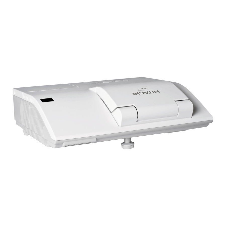
Page 13: Part Names
Introduction Part names HOT! Projector (1) Lamp cover ( The lamp unit is inside. (2) Control panel ( (12) (3) Elevator feet (x 2) ( (4) Remote sensor ( (14) (5) Lens ( (11) (6) Intake vents (13) (7) Filter cover ( (10) The air filter and intake vent HOT! - Page 14 Introduction Control panel (1) STANDBY/ON button ( (2) INPUT button ( 18, 101, 102) (3) POWER indicator ( 101, 102) (4) TEMP indicator ( 101, 102) (5) LAMP indicator ( Buttons ◄/►/▲/▼ (6) FOCUS +/- buttons 24), when no menu is displayed ( 28).
- Page 15 Introduction Remote control (1) VIDEO button ( (10) (2) COMPUTER button ( MY SOURCE/ (3) SEARCH button ( VIDEO COMPUTER DOC.CAMERA (4) STANDBY/ON button ( ASPECT AUTO SEARCH BLANK (16) (12) MAGNIFY PAGE VOLUME (5) ASPECT button ( FREEZE (14) (6) AUTO button ( DOWN (11)
-
Page 16: Setting Up
Setting up Setting up Install the projector according to the environment and manner the projector will be used in. Arrangement Refer to table T-1 or T-2 and figures F-1 and F-2 at the end of User’s Manual (concise) to determine the screen size and projection distance. The values shown in the table are calculated for a full size screen. - Page 17 Setting up Arrangement (continued) WARNING ►Place the projector in a cool place, and ensure that there is sufficient ventilation. The high temperature of the projector could cause fire, burns and/or malfunction of the projector. • Do not stop-up, block or otherwise cover the projector's vents. •...
-
Page 18: Connecting With Your Devices
Setting up Arrangement (continued) NOTE • The projector may make a rattling sound when tilted, moved or shaken, since a flap to control the air flow inside of the projector has moved. Be aware that this is not a failure or malfunction. Connecting with your devices Before connecting the projector to a device, consult the manual of the device to confirm that the device is suitable for connecting with this projector and prepare... - Page 19 Setting up Connecting with your devices (continued) About Plug-and-Play capability • Plug-and-Play is a system composed of a computer, its operating system and peripheral equipment (i.e. display devices). This projector is VESA DDC 2B compatible. Plug-and-Play can be used by connecting this projector to a computer that is VESA DDC (display data channel) compatible.
- Page 20 Setting up Connecting with your devices (continued) NOTE • Before connecting the projector to a computer, consult the computer’s manual and check the compatibility of the signal level, the synchronization methods and the display resolution output to the projector. - Some signal may need an adapter to input this projector. - Some computers have multiple screen display modes that may include some signals which are not supported by this projector.
- Page 21 Setting up Connecting with your devices (continued) • If you insert a USB storage device, such as a USB memory, into the USB TYPE A port and select the port as the input source, you can view images stored in the 78).
- Page 22 Setting up Connecting with your devices (continued) To use network functions of the projector, connect the LAN port with the computer's LAN port, or with an access point that is connected to the computer with wireless LAN, using a LAN cable. To use NETWORK BRIDGE function, also connect the CONTROL port and an RS-232C port of the external device to communicate as a network terminal.
-
Page 23: Connecting To A Power Supply
Setting up Connecting to a power supply Put the connector of the power cord into the AC IN (AC inlet) of the projector. Firmly plug the power cord’s plug into the outlet. In a couple of seconds after the power supply connection, the POWER indicator will light up in steady orange. -
Page 24: Using The Cable Cover
Setting up Using the cable cover Utilize the cable cover as the guard and blind for the connecting parts. Connect the signal cables and the power cord to the projector first. Combine parts as shown in figure, and assemble the cable cover. Insert the three knobs on the cable cover into the three holes on the projector as shown in the figure. -
Page 25: Remote Control
Holding the hook part of the battery cover, remove it. Align and insert the two AA batteries (HITACHI MAXELL or HITACHI MAXELL ENERGY, Part No.LR6 or R6P) according to their plus and minus terminals as indicated in the remote control. -
Page 26: Changing The Frequency Of Remote Control Signal
Remote control Changing the frequency of remote control signal The accessory remote control has the two choices on signal ASPECT AUTO SEARCH BLANK frequency Mode 1:NORMAL and Mode 2:HIGH. If the remote control MAGNIFY PAGE VOLUME FREEZE does not function properly, attempt to change the signal frequency. DOWN In order to set the Mode, please keep pressing the combination of MY BUTTON... -
Page 27: Power On/Off
Power on/off Power on/off Turning on the power STANDBY/ON button Make sure that the power cord is firmly POWER indicator and correctly connected to the projector and the outlet. Make sure that the POWER indicator is 101). steady orange ( Confirm that there is nothing that the lens door hits while opening. - Page 28 Power on/off Turning off the power Press the STANDBY/ON button on the projector or the remote control. The message “Power off?” will appear on the screen for about 5 seconds. Confirm that there is nothing that the lens door hits while closing. Press the STANDBY/ON button again while the message appears.
-
Page 29: Operating
Operating Operating VOLUME +/- button Adjusting the volume MY SOURCE/ VIDEO COMPUTER DOC.CAMERA Use the VOLUME +/VOLUME - buttons to adjust the volume. ASPECT AUTO SEARCH BLANK A dialog will appear on the screen to aid you in adjusting the MAGNIFY PAGE VOLUME... - Page 30 Operating Selecting an input signal (continued) COMPUTER button Press COMPUTER button on the remote control. Each time you press the button, the projector switches its input port from the current port as below. MY SOURCE/ VIDEO COMPUTER DOC.CAMERA COMPUTER IN1 COMPUTER IN2 ASPECT AUTO...
-
Page 31: Searching An Input Signal
Operating Searching an input signal Press SEARCH button on the remote control. SEARCH button The projector will start to check its input ports as below in order to find any input signals. MY SOURCE/ VIDEO COMPUTER DOC.CAMERA When an input is found, the projector will stop searching ASPECT AUTO SEARCH... -
Page 32: Adjusting The Projector's Elevator
Operating Adjusting the projector's elevator The projector has Front foot for inclinations and Rear foot for horizontals. Spacers on the each elevator foot are installed at the time of shipment, and projector is in a condition to be able to just project. If necessary, detach the spacer, and the elevator feet can be manually twisted to make more precise adjustments. -
Page 33: Using The Automatic Adjustment Feature
Operating FOCUS - button Press the FOCUS + or FOCUS – button on the remote control, or FOCUS + or FOCUS – button on the projector ( MY SOURCE/ VIDEO COMPUTER DOC.CAMERA while no menu is on screen, to display the FOCUS box on ASPECT AUTO SEARCH... -
Page 34: Adjusting The Position
Operating Adjusting the position POSITION MENU Press the POSITION button on the remote control while no menu 42) dialog on screen. is on screen, to display the D-SHIFT ( ENTER RESET Use the ▲, ▼, ◄ and ► buttons to adjust the picture position. Press the POSITION button again to finish this operation. -
Page 35: Using The Magnify Feature
Operating Using the magnify feature MAGNIFY Press the MAGNIFY ON button on the remote control. ON/OFF button The picture will be magnified, and the MAGNIFY dialog will appear on the screen. When the MAGNIFY ON button is MY SOURCE/ VIDEO COMPUTER DOC.CAMERA pressed for the first time after the projector is turned on, the... -
Page 36: Temporarily Freezing The Screen
Operating Temporarily freezing the screen FREEZE button Press the FREEZE button on the remote control. The “FREEZE” indication will appear on the screen (however, MY SOURCE/ the indication will not appear when the OFF is selected for VIDEO COMPUTER DOC.CAMERA 50)), and the the MESSAGE item in the SCREEN menu ( ASPECT... -
Page 37: Using The Menu Function
Operating Using the menu function This projector has the following menus: PICTURE, IMAGE, INPUT, SETUP, AUDIO, SCREEN, OPTION, NETWORK, SECURITY and EASY MENU. EASY MENU consists of functions often used, and the other menus are classified into each purpose and brought together as the ADVANCED MENU. Each of these menus is operated using the same methods. - Page 38 Operating Using the menu function (continued) To close the MENU, press the MENU button again or select EXIT and press the ◄ cursor button or ENTER button. Even if you do not do anything, the dialog will automatically disappear after about 30 seconds. ●...
-
Page 39: Easy Menu
EASY MENU EASY MENU From the EASY MENU, items shown in the table below can be performed. Select an item using the ▲/▼ cursor buttons. Then perform it according to the following table. Item Description Using the ◄/► buttons switches the mode for aspect ratio. ASPECT 35). -
Page 40: Advanced Menu , Exit
EASY MENU Item Description Using the ◄/► buttons switches the picture mode. The picture modes are combinations of GAMMA and COLOR TEMP settings. Choose a suitable mode according to the projected source. NORMAL CINEMA DYNAMIC BOARD(BLACK) DAYTIME WHITEBOARD BOARD(GREEN) GAMMA COLOR TEMP NORMAL 1 DEFAULT... -
Page 41: Picture Menu
PICTURE menu PICTURE menu From the PICTURE menu, items shown in the table below can be performed. Select an item using the ▲/▼ cursor buttons, and press the ► cursor button or ENTER button to execute the item. Then perform it according to the following table. Item Description Using the ◄/►... - Page 42 PICTURE menu Item Description Using the ▲/▼ buttons switches the color temperature mode. 1 HIGH 1 CUSTOM 2 MID 2 CUSTOM 6 CUSTOM 3 LOW 6 Hi-BRIGHT-3 3 CUSTOM 5 CUSTOM 5 Hi-BRIGHT-2 4 CUSTOM 4 Hi-BRIGHT-1 To adjust CUSTOM Selecting a mode whose name includes CUSTOM and then pressing the ►...
- Page 43 PICTURE menu Item Description Using the ◄/► buttons adjusts the sharpness. Weak Strong SHARPNESS • There may be some noise and/or the screen may flicker for a moment when an adjustment is made. This is not a malfunction. Using the ▲/▼ cursor buttons changes the active iris control mode. PRESENTATION THEATER PRESENTATION : The active iris displays the best presentation...
-
Page 44: Image Menu
IMAGE menu IMAGE menu From the IMAGE menu, items shown in the table below can be performed. Select an item using the ▲/▼ cursor buttons, and press the ► cursor button or ENTER button to execute the item. Then perform it according to the following table. - Page 45 IMAGE menu Item Description Using the ◄/► buttons adjusts the vertical position. Down • Over-adjusting the vertical position may cause noise to appear on the screen. If this occurs, please reset the vertical position to the default setting. Pressing the RESET button when the V POSITION V POSITION is selected will reset the V POSITION to the default setting.
- Page 46 IMAGE menu Item Description Using the ◄/► buttons adjusts the horizontal phase to eliminate flicker. Right Left H PHASE • This item can be selected only for a computer signal or a component video signal. This function is unavailable for a signal from the LAN, USB TYPE A, USB TYPE B or HDMI port.
-
Page 47: Input Menu
INPUT menu INPUT menu From the INPUT menu, items shown in the table below can be performed. Select an item using the ▲/▼ cursor buttons, and press the ► cursor button or ENTER button to execute the item. Then perform it according to the following table. - Page 48 INPUT menu Item Description The video format for S-VIDEO port and VIDEO port can be set. (1) Use the ▲/▼ buttons to select the input port. (2) Using the ◄/► buttons switches the mode for video format. AUTO NTSC SECAM VIDEO FORMAT N-PAL M-PAL...
- Page 49 INPUT menu Item Description The computer input signal type for COMPUTER IN1 and IN2 ports can be set. (1) Use the ▲/▼ buttons to select the COMPUTER IN port to be set. (2) Use the ◄/► buttons to select the computer input signal type. AUTO SYNC ON G OFF COMPUTER IN...
- Page 50 INPUT menu Item Description The resolution for the COMPUTER IN1 and COMPUTER IN2 input signals can be set on this projector. (1) In the INPUT menu select the RESOLUTION using the ▲/▼ buttons and press the ► button. The RESOLUTION menu will be displayed.
-
Page 51: Setup Menu
SETUP menu SETUP menu From the SETUP menu, items shown in the table below can be performed. Select an item using the ▲/▼ cursor buttons, and press the ► cursor button or ENTER button to execute the item. Then perform it according to the following table. - Page 52 SETUP menu Item Description Using the ▲/▼ cursor buttons selects the horizontal picture position. LEFT RIGHT The PICT. POSIT. H is not changed if any of the following cases apply. • The ASPECT is set to 16:9 or 16:10. • The input signal has an aspect ratio of 16:9, 16:10 or verticallly PICT.
- Page 53 SETUP menu Item Description This item allows you to adjust the shape of the projected image in each of the corners and sides. (1) Choose a corner or side to adjust using the ▲/▼/◄/► buttons and press the ENTER or INPUT button. (2) Adjust the distortion as below.
- Page 54 SETUP menu Item Description Using the ▲/▼ buttons changes the eco mode setting. NORMAL • When the ECO is selected, acoustic noise and screen brightness ECO MODE are reduced. 44) is set to ON, the projector will • When AUTO ECO MODE ( always be set to Eco mode at start-up regardless this setting.
-
Page 55: Audio Menu
AUDIO menu AUDIO menu From the AUDIO menu, items shown in the table below can be performed. Select an item using the ▲/▼ cursor buttons, and press the ► cursor button or the ENTER button to execute the item. Then perform it according to the following table. - Page 56 AUDIO menu Item Description Using the ▲/▼ buttons switches the mode for the HDMI audio. Check each of the two modes provided and select the suitable one HDMI AUDIO for your HDMI audio device. Using the ▲/▼ buttons switches the input level to match that of the microphone connected to the MIC port.
-
Page 57: Screen Menu
SCREEN menu SCREEN menu From the SCREEN menu, items shown in the table below can be performed. Select an item using the ▲/▼ cursor buttons, and press the ► cursor button or ENTER button to execute the item. Then perform it according to the following table. - Page 58 SCREEN menu Item Description This item allows you to capture an image for use as a MyScreen image which can be used as the BLANK screen and START UP screen. Display the image you want to capture before executing the following procedure.
- Page 59 SCREEN menu Item Description Using the ▲/▼ buttons turns on/off the MyScreen lock function. When the ON is selected, the item MyScreen is locked. Use this MyScreen Lock function for protecting the current MyScreen. • This function cannot be selected when the ON is selected to the 73).
- Page 60 SCREEN menu Item Description Each input port for this projector can have a name applied to it. (1) Use the ▲/▼ buttons on the SCREEN menu to select SOURCE NAME and press the ► or ENTER button. The SOURCE NAME menu will be displayed. (2) Use the ▲/▼...
- Page 61 SCREEN menu Item Description (6) The current name will be displayed on the first line. Use the ▲/▼/◄/► buttons and the ENTER or INPUT button to select and enter characters. To erase 1 character at one time, press the RESET button or press the ◄...
- Page 62 SCREEN menu Item Description The C.C. is the function that displays a transcript or dialog of the audio portion of a video, files or other presentation or other relevant sounds. It is required to have NTSC format video or 480i@60 format component video source supporting C.C.
-
Page 63: Option Menu
OPTION menu OPTION menu From the OPTION menu, items shown in the table below can be performed. Select an item using the ▲/▼ cursor buttons, and press the ► cursor button or ENTER button to execute the item, except for the items LAMP TIME and FILTER TIME. - Page 64 OPTION menu Item Description Using the ▲/▼ buttons adjusts the time to count down to automatically turn the projector off. Long (max. 99 minutes) Short (min. 0 minute = DISABLE) When the time is set to 0, the projector is not turned off automatically. AUTO POWER When the time is set to 1 to 99, and when the passed time with no- signal or an unsuitable signal reaches at the set time, the projector...
- Page 65 OPTION menu Item Description The lamp time is the usage time of the lamp, counted after the last resetting. It is shown in the OPTION menu. Pressing the RESET button on the remote control or the ► button of the projector displays a dialog. To reset the lamp time, select the OK using the ►...
- Page 66 OPTION menu Item Description This item is to assign one of the following functions to MY BUTTON 1/2 on the remote control ( (1) Use the ▲/▼ buttons on the MY BUTTON menu to select a MY BUTTON - (1/2) and press the ► or ENTER button to display the MY BUTTON setup dialog.
- Page 67 OPTION menu Item Description • ACTIVE IRIS: Changes the active iris mode. 31). • PICTURE MODE: Changes the PICTURE MODE ( 56). • FILTER RESET: Displays the filter time reset confirmation dialogue ( • TEMPLATE: Makes the template pattern selected to the 52) appear or disappear.
- Page 68 OPTION menu Item Description Selecting this item displays the SERVICE menu. Select an item using the ▲/▼ buttons, and press the ► button or the ENTER button on the remote control to execute the item. FAN SPEED Using the ▲/▼ buttons switches the rotation speed of the cooling fans.
- Page 69 OPTION menu Item Description KEY LOCK (1) Use the ▲/▼ buttons to select CONTROL PANEL or REMOTE CONTROL. (2) Use the ◄/► buttons to turn the key lock function on/off. When ON is selected, all buttons on the projector or remote control except the STANDBY/ON button are locked.
- Page 70 OPTION menu Item Description REMOTE FREQ. (1) Use the ▲/▼ button to change the projector's remote sensor 4, 17). frequency setting ( 1:NORMAL 2:HIGH (2) Use the ◄/► button to change the projector's remote sensor on or off. The factory default setting is for both 1:NORMAL and 2:HIGH to be on.
- Page 71 OPTION menu Item Description COMMUNICATION TYPE Select the communication type for transmission via the CONTROL port. NETWORK BRIDGE NETWORK BRIDGE: Select this type, if it is required to control an external device as a network terminal, via this projector from the computer. The CONTROL port doesn't accept RS-232C commands ( Network Bridge Function in the...
- Page 72 OPTION menu Item Description RESPONSE LIMIT TIME Select the time period to wait for receiving response data from other device communicating by the NETWORK BRIDGE and the HALF-DUPLEX through the CONTROL port. OFF: Select this mode if it is not required to check the responses from the device that the projector sends data to.
- Page 73 OPTION menu Item Description INFORMATION Selecting this item displays a dialog titled “INPUT_INFORMATION”. It shows the information about the current input. • The “FRAME LOCK” message on the dialog means the frame lock function is working. • This item can't be selected for no signal and sync out. SERVICE •...
-
Page 74: Network Menu
NETWORK menu NETWORK menu Remember that incorrect network settings on this projector may cause trouble on the network. Be sure to consult with your network administrator before connecting to an existing access point on your network. Select “NETWORK” from the main menu to access the following functions. - Page 75 NETWORK menu Item Description Use the ▲/▼/◄/► buttons to enter the IP ADDRESS. This function can only be used when DHCP is set to OFF. IP ADDRESS • The IP ADDRESS is the number that identifies this projector on the network. You cannot have two devices with the same IP ADDRESS on the same network.
- Page 76 NETWORK menu Item Description (1) Use the ▲/▼ buttons on the NETWORK menu to select the PROJECTOR NAME and press the ► button. The PROJECTOR NAME dialog will be displayed. (2) The current PROJECTOR NAME will be displayed on the first 3 lines.
- Page 77 NETWORK menu Item Description Selecting this item displays the MY IMAGE menu. To store images in the projector, the application software PJImg/Projector Image Tool that can be downloaded from our website is required. Use the ▲/▼ buttons to select an item which is a still image by the MY IMAGE ( My Image Function in the User’s manual - Network Guide) and the ►...
- Page 78 NETWORK menu Item Description Selecting this item displays the PRESENTATION menu. Use ▲/▼ buttons to select one of the following items, then press ► or ENTER button to use the function. If you set a computer to the Presenter mode while its image is projected, the projector is occupied by the computer and access from any other computer is blocked.
- Page 79 NETWORK menu Item Description • To change from Multi PC mode to Single PC mode, select one of computers in the dialog using the ▲/▼/◄/► buttons and press the ENTER or INPUT button. Press the ► button to choose OK, and then press ENTER or INPUT again.
- Page 80 NETWORK menu Item Description Selecting this item displays the NETWORK_INFORMATION dialog for confirming the network settings. INFORMATION • For the details of PASSCODE, see the section Selecting the network connection method in the User’s manual – Network Guide. • Only the first 16 characters of the projector name are displayed. •...
-
Page 81: Security Menu
SECURITY menu SECURITY menu This projector is equipped with security functions. From the SECURITY menu, items shown in the table below can be performed. To use SECURITY menu: User registration is required before using the security functions. Enter to the SECURITY menu 1. - Page 82 SECURITY menu Item Description The MyScreen PASSWORD function can be used to prohibit access to the MyScreen function and prevent the currently registered MyScreen image from being overwritten. 1 Turning on the MyScreen PASSWORD 1-1 Use the ▲/▼ buttons on the SECURITY menu to select MyScreen PASSWORD and press the ►...
- Page 83 SECURITY menu Item Description PIN LOCK is a function which prevents the projector from being used unless a registered Code is input. 1 Turning on the PIN LOCK 1-1 Use the ▲/▼ buttons on the SECURITY menu to select PIN LOCK and press the ► button or the ENTER button to display the PIN LOCK on/off menu.
-
Page 84: Ransition Detector , M
SECURITY menu Item Description If this function is set to ON when the vertical angle of the projector or MIRROR setting at which the projector is turned on is different than the previously recorded, the TRANSITION DETECTOR ON alarm will be displayed and the projector will not display the input signal. - Page 85 SECURITY menu Item Description The MY TEXT PASSWORD function can prevent the MY TEXT from being overwritten. When the password is set for the MY TEXT; • The MY TEXT DISPLAY menu will be unavailable, which can prohibit changing the DISPLAY setting. •...
- Page 86 SECURITY menu Item Description (1) Use the ▲/▼ buttons on the SECURITY menu to select the MY TEXT DISPLAY and press the ► or ENTER button to display the MY TEXT DISPLAY on/off menu. (2) Use the ▲/▼ buttons on the MY TEXT DISPLAY on/off menu to select on or off.
-
Page 87: Presentation Tools
Presentation tools Presentation tools The projector has the following two convenient tools that enable on-screen presentations easily and quickly: below) - PC-LESS Presentation ( - USB Display ( PC-LESS Presentation The PC-LESS Presentation reads image data from storage media inserted into the USB TYPE A port and displays the image on the following modes. - Page 88 Presentation tools PC-LESS Presentation (continued) Thumbnail mode The Thumbnail mode displays the images stored in a USB storage device on the Thumbnail screen. Maximum 20 images are displayed in a screen. If you wish, you can jump into the Full Screen mode or Slideshow mode, after you select some images in the Thumbnail mode.
- Page 89 Presentation tools PC-LESS Presentation (continued) Operating by buttons or keys You can control the images in the Thumbnail screen with the remote control or keypad or a web browser software. The following functions can be supported while the Thumbnail is displayed. Button operation Functions The keypad on...
- Page 90 Presentation tools PC-LESS Presentation (continued) Operating by the menu on the Thumbnail screen You can also control the images by using the menu on the Thumbnail screen. Item Functions Moves to an upper folder. SORT Allows you to sort files and folders as following. Press the ►...
- Page 91 Presentation tools PC-LESS Presentation (continued) NOTE • These operations are not accessible while the projector OSD is displayed. • The Thumbnail mode shows 20 pictures in 1 page as maximum. • It is not possible to change the input port by using the INPUT button when the Thumbnail screen, Slideshow, or Full Screen is displayed.
-
Page 92: Full Screen Mode
Presentation tools PC-LESS Presentation (continued) Full Screen Mode The Full Screen mode shows a full display image. To display in Full Screen mode, select an image in the Thumbnail screen. Then press the ENTER button on the remote control or the INPUT button on the keypad, or click [ENTER] on the Web Remote Control. -
Page 93: Slideshow Mode, Playlist
Presentation tools PC-LESS Presentation (continued) Slideshow mode The Slideshow mode displays images in full screen and switches the images at 79). intervals set in INTERVAL on the Thumbnail screen menu ( You can start this function from the Slideshow menu. To display the Slideshow menu, select the SLIDESHOW button in the Thumbnail mode and press the ENTER button on the remote control or INPUT button on the projector. - Page 94 Presentation tools PC-LESS Presentation (continued) You can play the Slideshow at your desired configuration. Configure the Slideshow items in the Thumbnail. 1) RETURN : Returns to the thumbnail mode. 2) PLAY : Play the Slideshow. 3) START : Set the beginning number of the Slideshow.
- Page 95 Presentation tools PC-LESS Presentation (continued) Playlist The Playlist is a DOS format text file, which decides the order of displayed still image files in the Thumbnail or Slideshow. The playlist file name is “playlist.txt” and it can be edited on a computer. It is created in the folder that contains the selected image files when the PC-LESS Presentation is started or the Slideshow is configured.
-
Page 96: Usb Display
• If "Waiting for connection." remains displayed while the USB cable is connected, remove the USB cable and reconnect after a while. • Please check and get the latest version at Hitachi Web site. http://www.hitachi-america.us/digitalmedia or http://www.hitachidigitalmedia.com Follow the instructions that can be obtained at the site for updating. - Page 97 Presentation tools USB Display (continued) This application will appear in the Windows notification area once it starts. You can quit the application from your computer by selecting “Quit” on the menu. NOTE • The “LiveViewer” (refer to the User's Manual - Network Guide) and this application cannot be used at the same time.
- Page 98 Presentation tools USB Display (continued) Right-Click menu The menu shown in the right will be displayed when you right-click the application icon in the Windows notification area. Display : The Floating menu is displayed, and the icon disappears from the Windows notification area.
-
Page 99: Options Window
Presentation tools USB Display (continued) Options window If you select the Option button on the Floating menu, the Options window is displayed. Optimize Performance The “LiveViewer Lite for USB” captures screenshots in JPEG data and sends them to the projector. The “LiveViewer Lite for USB” has two options that have different compression rate of JPEG data. - Page 100 Presentation tools USB Display (continued) Display LiveViewer Lite for USB If you want to display LiveViewer application window to the screen, please check the box. NOTE • The annotation layer may not display on the projector image when this option is OFF. About The version information of the “LiveViewer Lite for USB”.
-
Page 101: Maintenance
Maintenance Maintenance Replacing the lamp A lamp has finite product life. Using the lamp for long periods of time could cause the pictures darker or the color tone poor. Note that each lamp has a different lifetime, and some may burst or burn out soon after you start using them. Preparation of a new lamp and early replacement are recommended. -
Page 102: Lamp Warning
Maintenance Replacing the lamp (continued) Lamp warning HIGH TEMPERATURE HIGH PRESSURE HIGH VOLTAGE WARNING ►The projector uses a high-pressure mercury glass lamp. The lamp can break with a loud bang, or burn out, if jolted or scratched, handled while hot, or worn over time. -
Page 103: Cleaning And Replacing The Air Filter
Maintenance Cleaning and replacing the air filter The air filter unit of this projector consists of a filter cover, two kinds of filters, and a filter frame. The new double large filters system is expected to function longer. However, please check and clean it periodically to keep ventilation needed for normal operation of the projector. - Page 104 Maintenance Cleaning and replacing the air filter (continued) Turn the projector on and reset the filter time using the FILTER TIME item in the EASY MENU. (1) Press the MENU button to display a menu. (2) Point at the FILTER TIME using the ▼/▲ button, then press the ► button. A dialog will appear.
-
Page 105: Replacing The Internal Clock Battery
This projector has internal clock that uses a battery. When the clock of the network function does not work correctly, please try solution by replacement of the battery: HITACHI MAXELL or HITACHI MAXELL ENERGY, part number CR2032 or CR2032H. Battery cover Turn the projector off, and unplug the power cord. -
Page 106: Caring For The Mirror And Lens
Maintenance Caring for the mirror and lens If the projection mirror or lens is flawed, soiled or fogged, it could cause deterioration of display quality. Please take care of the mirror and lens, being cautious of handling. Turn the projector off and unplug the power cord from the power outlet. -
Page 107: Other Care
Maintenance Other care Inside of the projector In order to ensure the safe use of your projector, please have it cleaned and inspected by your dealer about once every year. Caring for the cabinet and remote control Incorrect care could have adverse influence such as discoloration, peeling paint, etc. -
Page 108: Troubleshooting
Troubleshooting Troubleshooting If an abnormal operation should occur, stop using the projector immediately. WARNING ►Never use the projector if abnormal operations such as smoke, Troubleshooting strange odor, excessive sound, damaged casing or elements or cables, penetration of liquids or foreign matter, etc. should occur. In such cases, immediately disconnect the power plug from the power outlet. - Page 109 Troubleshooting Related messages (continued) Message Description The internal temperature is rising. Please turn the power off, and allow the projector to cool down at least 20 minutes. After having confirmed the following items, please turn the power ON again. • Is there blockage of the air passage aperture? •...
-
Page 110: Regarding The Indicator Lamps
Troubleshooting Regarding the indicator lamps When operation of the LAMP, TEMP and POWER indicators differs from usual, check and cope with it according to the following table. POWER LAMP TEMP Description indicator indicator indicator Lighting Turned Turned The projector is in a standby state. Orange Please refer to the section “Power on/off”. - Page 111 Troubleshooting Regarding the indicator lamps (continued) POWER LAMP TEMP Description indicator indicator indicator There is a possibility that the interior portion has become heated. Please turn the power off, and allow the projector to cool down at least 20 minutes. After the projector has sufficiently cooled down, please make Blinking confirmation of the following items, and then turn the power on again.
-
Page 112: Resetting All Settings
Troubleshooting Resetting all settings When it is hard to correct some wrong settings, the FACTORY RESET function of 64) can reset all settings (except settings such SERVICE item in OPTION menu ( as LANGUAGE, LAMP TIME, FILTER TIME, FILTER MESSAGE, SECURITY and NETWORK) to the factory default. - Page 113 Troubleshooting Phenomena that may be easy to be mistaken for machine defects (continued) Reference Phenomenon Cases not involving a machine defect page The signal cables are not correctly connected. 9 ~ 13 Correctly connect the audio cables. The MUTE function is working. Restore the sound pressing MUTE or VOLUME +/- button on the remote control.
- Page 114 Troubleshooting Phenomena that may be easy to be mistaken for machine defects (continued) Reference Phenomenon Cases not involving a machine defect page The FREEZE function is working. Video screen display freezes. Press FREEZE button to restore the screen to normal. Color settings are not correctly adjusted.
- Page 115 Troubleshooting Phenomena that may be easy to be mistaken for machine defects (continued) Reference Phenomenon Cases not involving a machine defect page The computer The computer cannot start up in the current hardware connected to the configuration. USB TYPE B port Disconnect the USB cable from the computer, then of the projector reconnect it after starting up the computer.
-
Page 116: Specifications
Specifications Specifications Please see the Specifications in the User’s Manual (concise) which is a book. End User License Agreement for the Projector Software • Software in the projector consists of the plural number of independent software modules and there exist our copyright or/and third party copyrights for each of such software modules. - Page 117 Projector CP-A221N/CP-A301N/CP-AW251N (Type nos. CP-A221N, CP-A221NM, CP-A301N, CP-A301NM, CP-AW251N, CP-AW251NM) User's Manual (detailed) Network Guide Thank you for purchasing this product. This manual is intended to explain only the network function. For proper use of this product, please refer to this manual and the other manuals for this product. WARNING ►Before using this product, be sure to read all manuals for this product.
- Page 118 Contents Contents 1. Connection to the Network ............4 1.1 System requirements ................. 4 1.1.1 Required equipment preparation ..................4 1.1.2 Hardware and software requirement for computer ............4 1.2 Installing the “LiveViewer” ................6 1.2.1 Installing the “LiveViewer” ....................6 1.2.2 Updating the “LiveViewer”...
- Page 119 Contents 3. Web Control ................46 3.1 Logon ....................... 47 3.2 Network Information ................. 49 3.3 Network Settings ..................50 3.4 Port Settings ..................... 51 3.5 Mail Settings ..................... 53 3.6 Alert Settings .................... 54 3.7 Schedule Settings ..................56 3.8 Date/Time Settings ...................
-
Page 120: Connection To The Network
1. Connection to the network 1. Connection to the Network 1.1 System requirements 1.1.1 Required equipment preparation The following equipments are required to connect the projector to your computer through the network. Projector LAN cable (to connect the projector to a network): CAT-5 or greater Computer (minimum 1 set): equipped with the network feature (100Base-TX or 10Base-T) 1.1.2 Hardware and software requirement for computer... - Page 121 1. Connection to the network 1.1 System requirements (continued) NOTE • Referring to the manual of your computer or Windows, select the following or a smaller display resolution for the computer. CP-A221N, CP-A301N: 1024 x 768 (XGA) CP-AW251N: 1280 x 800 (WXGA) When a resolution larger than the specified resolution is selected, the projector will convert and display in the specified resolution, and the display speed may become faster.
-
Page 122: Installing The "Liveviewer
1. Connection to the network 1.2 Installing the “LiveViewer” 1.2.1 Installing the “LiveViewer” The “LiveViewer” software needs to be installed on all the computers to connect to the projector through a network. You need to log in as an administrator user to install the software. 1) Turn on the computer. - Page 123 1. Connection to the network 1.2 Installing the “LiveViewer” (continued) 6) The License Agreement dialog appears. If you accept it, select “I accept the terms of the license agreement” and press the [Next]. 7) The Choose Destination Location dialog appears. Press the [Next]. NOTE •...
-
Page 124: Updating The "Liveviewer
1. Connection to the network 1.2 Installing the “LiveViewer” (continued) 1.2.2 Updating the “LiveViewer” Please check and get the latest version at Hitachi Web site. http://www.hitachi-america.us/digitalmedia or http://www.hitachidigitalmedia.com Some functions explained in this manual require the “LiveViewer” Version 4.xx. (In the version information a number between 00 and 99 will replace the xx.) -
Page 125: Process To Connect The Network
1. Connection to the network 1.3 Process to connect the network Before connecting your computer and projector via a network, make sure that the LAN port is selected as the input source on the projector. ( Operating in the User’s Manual – Operating Guide) Otherwise a connection cannot be established. 1.3.1 Process overview An overview of the process to connect your computer and the projector via a network is shown below. -
Page 126: Starting The "Liveviewer
1. Connection to the network 1.3 Process to connect the network (continued) 1.3.2 Starting the “LiveViewer” Start the “LiveViewer” in your computer, taking one of the followings. • Double click the “LiveViewer” icon on the Desktop in your computer. • Select “Start” → “All Programs” → “Projector Tools” → “LiveViewer” on Windows menu. -
Page 127: Selecting The Network Connection Mode
1. Connection to the network 1.4 Selecting the network connection mode After starting the “LiveViewer”, the “Select the Network Connection” screen comes up. Select the network connection that you would like to use. There are 3 options in the menu. •... - Page 128 1. Connection to the network 1.4 Selecting the network connection mode (continued) A network connection was not established. The screen is displayed in the case that the projector is not connected with a LAN cable to your computer when the wired LAN is selected.
-
Page 129: Selecting My Connection
1. Connection to the network 1.4 Selecting the network connection mode (continued) 1.4.2 Selecting My Connection Select the [My Connection] and click the [Connect]. If you select the My Connection, the computer is connected to the projector through the network by using the profile data that is pre- assigned to My Connection. - Page 130 1. Connection to the network 1.4 Selecting the network connection mode (continued) Are you sure you want to connect the selected projector? The message is appeared when the wireless adapter you selected is already used for another network connection. • To connect, click the [Yes]. Proceed to item 1.8 Confirming the connection to your destination.
-
Page 131: Selecting The Network Connection Method
1. Connection to the network 1.5 Selecting the network connection method There are some options to connect to the network. • Enter PassCode • Configure Manually • Select From List Select one of them to meet your requirement. Enter PassCode If you want to use the Passcode for network connection, select the [Enter PassCode] and click the [Next]. -
Page 132: Passcode Connection
1. Connection to the network 1.5 Selecting the network connection method (continued) 1.5.1 Passcode connection The unique Passcode system brings you very quick and simple connection to the network. The Passcode is a code that expresses the network setting in the projector. If you input the code in the “LiveViewer”... - Page 133 1. Connection to the network 1.5 Selecting the network connection method (continued) Method 2 1) Turn on the projector, and make sure that the projector image is on screen. 2) Press the MENU button on the remote control or the ▲/▼ buttons on the projector to show the menu on screen.
- Page 134 1. Connection to the network 1.5 Selecting the network connection method (continued) (2) Entering the Passcode If you select [Enter PassCode] at item 1.5, the “Please enter the PassCode” screen is displayed. Please enter the Passcode divided 4-digit each in 3 boxes (total 12-digit). Example PASSCODE: 1234 - 5678 - 9ABC After entering the Passcode, click the [Connect] to start the connection to the projector.
- Page 135 1. Connection to the network 1.5 Selecting the network connection method (continued) A network connection could not be established. Windows prevented network configuration changes. You may log in the Windows under User authority. Click the [OK], then the “LiveViewer” main menu is displayed even though the network is not established.
- Page 136 1. Connection to the network 1.5 Selecting the network connection method (continued) If you put a check mark in the box “Not displaying confirmation dialog for adding Network settings”, the projector memorizes current configuration and this dialog is not displayed again. To display this dialog again, click Option icon in the “LiveViewer”...
- Page 137 1. Connection to the network 1.5 Selecting the network connection method (continued) Are you sure you want to connect the selected projector? The message is appeared when the wireless adapter you selected is already used for another network connection. • To connect, click the [Yes]. Proceed to item 1.8 Confirming the connection to your destination.
- Page 138 1. Connection to the network 1.5 Selecting the network connection method (continued) (3) Confi guring manually 18), you are required to enter the network After entering the Passcode ( confi guration manually if you use a Subnet mask other than Class A, B or C. ( 23).
- Page 139 1. Connection to the network 1.5 Selecting the network connection method (continued) Wired LAN 1) Enter the following information for the projector. Subnet mask *1: 255.255.255.128 (example) 2) Click the [Connect]. 3) The network connection will be established. Proceed to item 1.8 Confirming the connection to your destination.
-
Page 140: Manual Configuration
1. Connection to the network 1.6 Manual configuration There are 3 options for the manual configuration. below) • Profile ( • History ( • Configure Network Settings Manually ( If you select Configure Network Settings Manually, proceed to item 1.7 Configuring the network settings manually. -
Page 141: History Connection
1. Connection to the network 1.6 Manual configuration (continued) 1.6.2 History connection The “LiveViewer” can memory the network settings when connecting to the projector as a history record. After that, selecting a history record can quickly connect the network with the projector. -
Page 142: Configuring The Network Settings Manually
1. Connection to the network 1.7 Configuring the network settings manually All setting for the network connection between the projector and computer is input manually. Select the [Configure Network Settings Manually]. The information to be input manually is different, depending on how you want to connect the projector and computer. - Page 143 1. Connection to the network 1.7 Confi guring the network settings manually (continued) Wireless LAN 1) The setting on the access point. *1 Enter the following information. SSID: WirelessAccessPoint (example) Encryption: WEP64bit (example) Encryption key *2: ********** (example) Mode: INFRASTRUCTURE 2) Click the [Next].
- Page 144 1. Connection to the network 1.7 Configuring the network settings manually (continued) Wired LAN 1) Enter the following information for the projector. *1 IP address : 192.168.1.10 (example) Subnet mask : 255.255.255.0 (example) 2) Click the [Connect]. 3) The network connection will be established. Proceed to item 1.8 Confirming the connection to your destination.
- Page 145 1. Connection to the network 1.7 Configuring the network settings manually (continued) If you need to add a Network configuration on your computer to connect to the projector. This dialog will be displayed when you need to add a Network configuration on your computer to connect to the projector.
- Page 146 1. Connection to the network 1.7 Configuring the network settings manually (continued) If the entered IP address and projector's IP address are the same, a warning dialog shown to the right will be displayed. Click the [OK], and then enter a different IP address from the projector's one in the dialog for changing Network configuration.
-
Page 147: Confirming The Connection To Your Destination
1. Connection to the network 1.8 Confirming the connection to your destination 1.8.1 Connection and transmission When the network connection is established, the “Connection to Projector successful” screen is displayed. Make sure that the right projector that you want to send your image to is selected, by checking the projector name and IP address shown in the screen. - Page 148 1. Connection to the network 1.8 Confirming the connection to your destination (continued) A Slideshow is currently running on the projector that you are trying to display to. The projector you want to send your images to is in the Slideshow mode in the PC-LESS Presentation.
-
Page 149: Connection Error
1. Connection to the network 1.8 Confirming the connection to your destination (continued) 1.8.2 Connection error When the connection to the projector could not be established, an error message, “Network Connection not established”, will come up. Click the [OK] then the “LiveViewer” main menu is displayed even though the network is not established. -
Page 150: Profile Data
1. Connection to the network 1.9 Profile data 1.9.1 Outline of Profile data The network setting to connect the projector and computer can be stored as a profile data. Once the data is stored, all you need to do is to select the data to connect to the network. -
Page 151: Editing Profile Data
1. Connection to the network 1.9 Profile data (continued) 1.9.3 Editing Profile data If necessary, the profile data can be edited on the Manual Configuration screen. ( 1) Select the [Profile], and select one of the data listed in the window. 2) Click the [Edit]. -
Page 152: Registering My Connection
1. Connection to the network 1.9 Profile data (continued) 1.9.4 Registering My Connection One of the profile data, which is often used, can be registered as the My Connection profile data. Once the data is registered, all you need to do is to select the My Connection to connect to the network. - Page 153 1. Connection to the network 1.9 Profile data (continued) Also, you can register a profile data to My Connection, when the network connection is established. When it is established, the “Connection to Projector successful” screen is displayed. ( If you wish to use the current connection setting for My Connection, check in the box for the [Register this setting to My Connection].
-
Page 154: Network Presentation
2. Network Presentation 2. Network Presentation 2.1 Using the “LiveViewer” When you get the connection between your projector and computer, the “LiveViewer” main menu will be shown on the computer screen. On the main menu you can configure settings and operate functions to send your images to the projector. - Page 155 2. Network Presentation 2.1 Using the “LiveViewer” (continued) e Hold button The image on screen is temporally frozen. The last image before the button is clicked is remained on screen. You can revise the image data on your computer without showing it on the projector’s screen.
-
Page 156: Displaying The Status
2. Network Presentation 2.1 Using the “LiveViewer” (continued) 2.1.2 Displaying the status 1) Indicator The indicator shows the following status. Indicator Status Note The network connection to the projector is Not connected not established yet. The network connection is established, but Hold the image transmissions on hold. -
Page 157: Switching The Display Mode
2. Network Presentation 2.1 Using the “LiveViewer” (continued) 2.1.3 Switching the display mode The “LiveViewer” has the Single PC mode and Multi PC mode. The modes can be switched on the main menu. 1) Click the button on the main menu. The buttons below are displayed. -
Page 158: Option Menu
2. Network Presentation 2.1 Using the “LiveViewer” (continued) 2.1.4 Option menu Clicking the Option button displays the option menu on screen. q “Not displaying confirmation dialog for adding Network settings” This setting allows you to choose to display or not the confirmation dialog for 20, 29) when you connect your computer adding a Network configuration ( to the projector. - Page 159 2. Network Presentation 2.1 Using the “LiveViewer” (continued) e Presenter Mode In the Single PC mode, the projector can be occupied by one computer and can block an access from any other computer, if the Presenter mode is selected in the “LiveViewer”. While making your presentation, you don’t need to worry that the image on screen is unexpectedly switched to an image sent by another computer.
-
Page 160: Starting The Network Presentation
2. Network Presentation 2.2 Starting the Network Presentation This chapter explains the Network Presentation feature with which you can project computer images transmitted through a network. The “LiveViewer” allows you to project images from one or multiple computers by connecting the projector to an existing network without using computer cables. This Network Presentation feature helps you to smoothly make your presentations and conduct conferences. -
Page 161: Presenter Mode
2. Network Presentation 2.2 Starting the Network Presentation (continued) 2) Multi PC mode The projector screen is divided to 4 zones. The projector displays images in one zone sent by a computer, so that the projector can display images sent by up to 4 computers at the same time. -
Page 162: Web Control
3. Web Control 3. Web Control You can adjust or control the projector via a network from a web browser on a computer that is connected to the same network. NOTE • Internet Explorer 6.0 or later is required. • If JavaScript is disabled in your web browser configuration, you must enable JavaScript in order to use the projector web pages properly. -
Page 163: Logon
3. Web Control 3.1 Logon To use the Web Control function, you need to logon with your user name and password. ( Refer to the following for configuring or controlling the projector via a web browser. Example: If the IP address of the projector is set to 192.168.1.10: 1) Display the logon window as shown on the right. - Page 164 3. Web Control 3.1 Logon (Continued) Below are the factory default settings for user name and password. User name Password Administrator <blank> If you logon successfully, the screen below will be displayed. Main menu 3) Click the desired operation or configuration item on the main menu.
-
Page 165: Network Information
3. Web Control 3.2 Network Information Displays the projector’s current network configuration settings. Item Description Projector Name Displays the projector name settings. DHCP Displays the DHCP configuration settings. IP Address Displays the current IP address. Subnet Mask Displays the subnet mask. Default Gateway Displays the default gateway. -
Page 166: Network Settings
3. Web Control 3.3 Network Settings Displays and configures network settings. Item Description IP Configuration Configures network settings. DHCP ON Enables DHCP. DHCP OFF Disables DHCP. IP Address Configures the IP address when DHCP is disabled. Subnet Mask Configures the subnet mask when DHCP is disabled. Default Gateway Configures the default gateway when DHCP is disabled. -
Page 167: Port Settings
3. Web Control 3.4 Port Settings Displays and configures communication port settings. Item Description Network Control Port1 Configures command control port 1 (Port:23). (Port:23) Port open Click the [Enable] check box to use port 23. Click the [Enable] check box when authentication is required Authentication for this port. - Page 168 3. Web Control 3.4 Port Settings (Continued) Item Description SNMP Port Configures the SNMP port. Port open Click the [Enable] check box to use SNMP. Configures the destination of the SNMP Trap in IP format. • The address allows not only IP address but also domain Trap address name if the valid DNS server is setup in the Network Settings.
-
Page 169: Mail Settings
3. Web Control 3.5 Mail Settings Displays and configures e-mail addressing settings. Item Description Click the [Enable] check box to use the e-mail function. Send Mail Configure the conditions for sending e-mail under the Alert Settings. Configures the address of the mail server in IP format. •... -
Page 170: Alert Settings
3. Web Control 3.6 Alert Settings Displays and configures failure & alert settings. Item Description Cover Error The lamp cover has not been properly fixed. Fan Error The cooling fan is not operating. The lamp does not light, and there is a possibility that interior Lamp Error portion has become heated. - Page 171 3. Web Control 3.6 Alert Settings (Continued) The Alert Items are shown below. Item Description Configures the time to alert. Alarm Time (Only Lamp Time Alarm and Filter Time Alarm.) SNMP Trap Click the [Enable] check box to enable SNMP Trap alerts. Click the [Enable] check box to enable e-mail alerts.
-
Page 172: Schedule Settings
3. Web Control 3.7 Schedule Settings Displays and configures schedule settings. Item Description Daily Configures the daily schedule. Sunday Configures the Sunday schedule. Monday Configures the Monday schedule. Tuesday Configures the Tuesday schedule. Wednesday Configures the Wednesday schedule. Thursday Configures the Thursday schedule. Friday Configures the Friday schedule. - Page 173 3. Web Control 3.7 Schedule Settings (Continued) The schedule settings are shown below. Item Description Schedule Click the [Enable] check box to enable the schedule. Configures the month and date. Date (Month/Day) This item appears only when Specific date (No. 1-5) is selected.
- Page 174 3. Web Control 3.7 Schedule Settings (Continued) NOTE • After the projector is moved, check the date and time set for the projector before configuring the schedules. Strong shock may make the date 59) get out of tune. and time settings ( •...
-
Page 175: Date/Time Settings
3. Web Control 3.8 Date/Time Settings Displays and configures the date and time settings. Item Description Current Date Configures the current date in year/month/day format. Current Time Configures the current time in hour:minute:second format. Click the [ON] check box to enable daylight savings time and Daylight Savings Time set the following items. - Page 176 3. Web Control 3.8 Date/Time Settings (Continued) Item Description Configures the time difference. Set the same time difference Time difference as the one set on your computer. If unsure, consult your IT manager. Click the [ON] check box to retrieve Date and Time SNTP information from the SNTP server and set the following items.
-
Page 177: Security Settings
3. Web Control 3.9 Security Settings Displays and configures passwords and other security settings. Item Description User Account Configures the user name and password. Configures the user name. User name The length of the text can be up to 32 alphanumeric characters. -
Page 178: Projector Control
3. Web Control 3.10 Projector Control The items shown in the table below can be performed using the Projector Control menu. Select an item with the mouse. Most of the items have a submenu. Refer to the table below for details. NOTE •... - Page 179 3. Web Control 3.10 Projector Control (Continued) Item Description PICTURE BRIGHTNESS Adjusts the brightness setting. CONTRAST Adjusts the contrast setting. GAMMA Selects the gamma setting. COLOR TEMP Selects the color temperature setting. COLOR Adjusts the color setting. TINT Adjusts the tint setting. SHARPNESS Adjusts the sharpness setting.
- Page 180 3. Web Control 3.10 Projector Control (Continued) Item Description SETUP D-ZOOM Adjusts the zoom. D-SHIFT V Adjusts the vertical picture position. D-SHIFT H Adjusts the horizontal picture position. PICTURE POSITION (CP-A221N, Selects the vertical picture position. CP-A301N) PICT.POSIT.H Selects the horizontal picture position. (CP-AW251N) KEYSTONE V Adjusts the vertical keystone distortion setting.
- Page 181 3. Web Control 3.10 Projector Control (Continued) Item Description AUDIO VOLUME Adjusts the volume setting. SPEAKER Turns the built-in speaker on/off. AUDIO SOURCE - Assigns the AUDIO SOURCE - COMPUTER IN1 input port. COMPUTER IN1 AUDIO SOURCE - Assigns the AUDIO SOURCE - COMPUTER IN2 input port. COMPUTER IN2 AUDIO SOURCE - Assigns the AUDIO SOURCE - LAN input port.
- Page 182 3. Web Control 3.10 Projector Control (Continued) Item Description OPTION AUTO SEARCH Turns the automatic signal search function on/off. DIRECT POWER ON Turns the direct power on function on/off. Configures the timer to shut off the projector when no signal AUTO POWER OFF is detected.
- Page 183 3. Web Control 3.10 Projector Control (Continued) The items shown in the table below can be performed using the Projector Control menu. Click the [Quit Presenter Mode]. Item Description SERVICE Quit Presenter Mode Quit compulsorily from the Presenter mode.
-
Page 184: Remote Control
3. Web Control 3.11 Remote Control You can use your Web browser to control the projector. • Do not attempt to control the projector with the projector’s remote control and via your Web browser at the same time. It may cause some operational errors in the projector. -
Page 185: Projector Status
3. Web Control 3.12 Projector Status Displays and configures the current projector status. Item Description Error Status Displays the current error status Lamp Time Displays the usage time for the current lamp. Filter Time Displays the usage time for the current filter. Power Status Displays the current power status. -
Page 186: Network Restart
3. Web Control 3.13 Network Restart Restarts the projector’s network connection. Item Description Restarts the projector’s network connection in order to Restart activate new configuration settings. NOTE • Restarting requires you to re-log on in order to further control or configure the projector via a web browser. -
Page 187: My Image Function
MY IMAGE transmission requires an exclusive application for your computer. Use the application to transfer the image data. It can be downloaded from the Hitachi web site (http://www.hitachi-america.us/ digitalmedia or http://www.hitachidigitalmedia.com). Refer to the manual for the application for instructions. - Page 188 4. My Image Function 4. My Image Function (Continued) Configure the following items from a web browser when MY IMAGE function is used. Example: If the IP address of the projector is set to 192.168.1.10: 1) Enter "http://192.168.1.10/" into the address bar of the web browser. 2) Enter your user name and password, and then click the [OK].
-
Page 189: Messeger Function
Messenger function requires an exclusive application for your computer. To edit, transfer and display the text data, use the application. You can download it from the Hitachi web site (http://www.hitachi-america.us/digitalmedia or http://www. hitachidigitalmedia.com). Refer to the manual for the application for the details of Messenger function and instructions of the application. - Page 190 5. Messenger Function 5. Messenger Function (Continued) Configure the following items from a web browser when Messenger function is used. Example: If the IP address of the projector is set to 192.168.1.10: 1) Enter "http://192.168.1.10/" into the address bar of the web browser. 2) Enter your user name and password, and then click the [OK].
-
Page 191: Network Bridge Function
6. Network Bridge Function 6. Network Bridge Function This projector is equipped with the NETWORK BRIDGE function to perform mutual conversion of a network protocol and a serial interface. Using the NETWORK BRIDGE function, a computer that is connected with this projector by Ethernet communication can control an external device that is connected with this projector by RS-232C communication as a network terminal. -
Page 192: Communication Setup
6. Network Bridge Function 6.2 Communication setup To configure the setup of the communication using NETWORK BRIDGE for the projector, use items in the COMMUNICATION menu. Open the menu of the projector and select the OPTION - SERVICE - COMMUNICATION menu. OPTION menu –... -
Page 193: Transmission Method
6. Network Bridge Function 6.4 Transmission method The transmission method can be selected from the menus, only when the NETWORK BRIDGE is selected for the COMMUNICATION TYPE. OPTION menu – SERVICE – COMMUNICATION in the User’s Manual – Operating Guide) HALF-DUPLEX FULL-DUPLEX 6.4.1 HALF-DUPLEX... -
Page 194: Full-Duplex
6. Network Bridge Function 6.4 Transmission method (Continued) NOTE • With using the HALF-DUPLEX method, the projector can send out 254 byte data as maximum at once. • If it is not required to monitor the response data from an external device and the RESPONSE LIMIT TIME is set to OFF, the projector can receive the data from the computer and send it out to an external device continuously. -
Page 195: Other Functions
7. Other Functions 7. Other Functions 7.1 E-mail Alerts The projector can automatically send an alert message to the specified e-mail addresses when the projector detects a certain condition that is requiring maintenance or detected an error. NOTE • Up to five e-mail addresses can be specified. •... - Page 196 7. Other Functions 7.1 E-mail Alerts (Continued) 5) Click the [Alert Settings] on the main menu to configure the E-mail Alerts settings. 54) for 6) Select and configure each alert item. Refer to item 3.6 Alert Setting ( further information. 7) Click the [Apply] button to save the settings.
-
Page 197: Projector Management Using Snmp
7. Other Functions 7.2 Projector Management using SNMP The SNMP (Simple Network Management Protocol) enables to manage the projector information, which is a failure or warning status, from the computer on the network. The SNMP management software will be required on the computer to use this function. -
Page 198: Event Scheduling
7. Other Functions 7.3 Event Scheduling The scheduling function enables to setup scheduled events including power on / power off. It enables to be “self-management” projector. NOTE • You can schedule the following control events: Power, Input Source, My Image, Messenger, Slideshow. ( •... - Page 199 7. Other Functions 7.3 Event Scheduling(Continued) Schedule Settings ( Schedule settings can be configured from a web browser. Example: If the IP address of the projector is set to 192.168.1.10: 1) Enter “http://192.168.1.10/” into the address bar of the web browser. 2) Enter your user name and password, and then click the [OK].
- Page 200 7. Other Functions 7.3 Event Scheduling(Continued) Date/Time Settings ( The Date/Time setting can be adjusted via a web browser. Example: If the IP address of the projector is set to 192.168.1.10: 1) Enter “http://192.168.1.10/” into the address bar of the web browser. 2) Enter your user name and password, and then click the [OK].
-
Page 201: Command Control Via The Network
7. Other Functions 7.4 Command Control via the Network You can configure and control the projector via the network using RS-232C commands. Communication Port The following two ports are assigned for the command control. TCP #23 (Network Control Port1 (Port: 23)) TCP #9715 (Network Control Port2 (Port: 9715)) NOTE •... - Page 202 7. Other Functions 7.4 Command Control via the Network (Continued) When the authentication setting is enabled, the following settings are required. 7) Click the [Security Settings] on the main menu. 8) Click the [Network Control] and enter the desired authentication password. * See NOTE.
- Page 203 7. Other Functions 7.4 Command Control via the Network (Continued) Command Format Command formats differ among the different communication ports. ● TCP #23 You can use the RS-232C commands without any changes. The reply data format is the same as the RS-232C commands. ( “RS-232C Communication”...
- Page 204 7. Other Functions 7.4 Command Control via the Network (Continued) Reply Data format The connection ID (the data is same as the connection ID data on the sending data format) is attached to the RS-232C commands reply data. <ACK reply> Connection Reply 0x06...
- Page 205 7. Other Functions 7.4 Command Control via the Network (Continued) Automatic Connection Break The TCP connection will be automatically disconnected after there is no communication for 30 seconds after being established. Authentication The projector does not accept commands without authentication success when authentication is enabled.
-
Page 206: Troubleshooting
8. Troubleshooting 8. Troubleshooting Reference Problem Likely Cause Things to Check Page Number The projector is not turned Is the projector’s lamp on? No image The projector’s input source Is the projector switched to *20, *21 isn’t switched to LAN. LAN? Check the network configurations of the... - Page 207 8. Troubleshooting 8. Troubleshooting (Continued) Reference Problem Likely Cause Things to Check Page Number The projector isn’t capable Switching the priority to of relaying dynamic images ‘Transmission Speed’ under The projected ® such as PowerPoint the options menu may help image is rather animation at full speed.
- Page 208 8. Troubleshooting 8. Troubleshooting (Continued) Reference Problem Likely Cause Things to Check Page Number Others Communication between - Information from the the projector and computer projector to computer is is not working well. Try “RESTART” in not correct or completed SERVICE menu under the - The projector does not NETWORK Functions of...
-
Page 209: Warranty And After-Sales Service
9. Warranty and after-sales service 9. Warranty and after-sales service If a problem occurs with the equipment, please read 8. Troubleshooting ( section first and review all suggested check points. After that, please contact your dealer or service company, if you still have the problem. They will tell you what warranty condition is applied. - Page 210 Projector CP-A221N/CP-A301N/CP-AW251N (Type nos. CP-A221N, CP-A221NM, CP-A301N, CP-A301NM, CP-AW251N, CP-AW251NM) User's Manual (detailed) Operating Guide – Technical Example of computer signal Resolution (H x V) H. frequency (kHz) V. frequency (Hz) Rating Signal mode 720 x 400 37.9 85.0 VESA TEXT 640 x 480 31.5...
- Page 211 Initial set signals Initial set signals The following signals are used for the initial settings. The signal timing of some computer models may be different. In such case, adjust the items V POSITION and H POSITION in the IMAGE menu. Back porch (B) Front porch (D) Back porch (b)
-
Page 212: Monitor Out
Connection to the ports Connection to the ports NOTICE ►Use the cables with straight plugs, not L-shaped ones, as the input ports of the projector are recessed. ►Only the signal that is input from the COMPUTER IN1 or IN2 can be output from the MONITOR OUT port. - Page 213 Connection to the ports (continued) COMPUTER IN2 COMPUTER IN1 HDMI USB TYPE B TYPE A DC5V 0.5A S-VIDEO AUDIO OUT AUDIO IN1 AUDIO IN3 MONITOR OUT CONTROL AUDIO IN2 VIDEO S-VIDEO Mini DIN 4pin jack • System: NTSC, PAL, SECAM, PAL-M, PAL-N, NTSC4.43, PAL(60Hz) Signal Color signal 0.286Vp-p (NTSC, burst), 75Ω...
- Page 214 Connection to the ports (continued) COMPUTER IN2 COMPUTER IN1 HDMI USB TYPE B TYPE A DC5V 0.5A S-VIDEO AUDIO IN1 AUDIO IN3 AUDIO OUT MONITOR OUT CONTROL VIDEO AUDIO IN2 HDMI 10 12 14 16 18 • Type :Digital audio/video connector 11 13 15 17 19 •...
- Page 215 Connection to the ports (continued) COMPUTER IN2 COMPUTER IN1 HDMI USB TYPE B TYPE A DC5V 0.5A S-VIDEO AUDIO OUT AUDIO IN1 AUDIO IN3 MONITOR OUT CONTROL AUDIO IN2 VIDEO USB TYPE A USB TYPE B USB A type jack USB B type jack Signal Signal...
- Page 216 Connection to the ports (continued) To input component video signal to COMPUTER IN ports D-sub plug COMPUTER IN2 COMPUTER IN1 HDMI USB TYPE B RCA plugs TYPE A DC5V 0.5A S-VIDEO AUDIO OUT AUDIO IN1 AUDIO IN3 RCA connectors COMPONENT VIDEO OUT MONITOR OUT CONTROL VIDEO...
- Page 217 RS-232C Communication RS-232C Communication When the projector connects to the computer by RS-232C communication, the projector can be controlled with RS-232C commands from the computer. For details of RS-232C commands, refer to RS-232C Communication / Network 17). command table ( Connection Turn off the projector and the computer.
-
Page 218: Communication Settings
RS-232C Communication (continued) Communication settings 1. Protocol 19200bps,8N1 2. Command format ("h" shows hexadecimal) Byte Number Command Header Data Header Data Setting Action Type code size flag code Packet Action <SET>Change setting to desired value [(cL)(cH)] (aL) (aH) 01h 00h (bL) (bH) (cL) (cH) by [(bL)(bH)]. - Page 219 RS-232C Communication (continued) 3. Response code / Error code ("h" shows hexadecimal) (1) ACK reply : 06h When the projector receives the Set, Increment, Decrement or Execute command correctly, the projector changes the setting data for the specified item by [Type], and it returns the code. (2) NAK reply : 15h When the projector cannot understand the received command, the projector returns the error code.
- Page 220 Command Control via the Network Command Control via the Network When the projector connects network, the projector can be controlled with RS- 232C commands from the computer with web browser. For details of RS-232C commands, refer to RS-232C Communication / Network 17).
- Page 221 Command Control via the Network (continued) Communicaion Port The following two ports are assigned for the command control. TCP #23 TCP #9715 Configure the following items form a web browser when command control is used. Port Settings Click the [Enable] check box to open [Network Port open Control Port1 (Port: 23)] to use TCP #23.
-
Page 222: Command Control Settings
Command Control via the Network (continued) Command control settings [TCP #23] 1. Command format Same as RS-232C communication, refer to RS-232C Communicaton command format. 2. Response code / Error code ("h" shows hexadecimal) Four of the response / error code used for TCP#23 are the same as RS-232C Communication (1)~(4). - Page 223 Command Control via the Network (continued) 2. Response code / Error code ("h" shows hexadecimal) The connection ID is attached for the TCP#23's response / error codes are used. The connection ID is same as the sending command format. (××h : connection ID) (1) ACK reply : 06h + ××h (2) NAK reply : 15h + ××h (3) Error reply : 1Ch + 0000h + ××h...
- Page 224 Network Bridge Communication Network Bridge Communication This projector is equipped with NETWORK BRIDGE function. When the projector connects to the computer by LAN communicaton, an external device that is connected with this projector by RS-232C communication can be controlled from the computer as a network terminal. For details, see the 6.
- Page 225 Network Bridge Communication (continued) Communication settings For communication setting, use the OPTION - SERVICE - COMMUNICATION menu. ( OPTION menu - SERVICE - COMMUNICATION in the User's Manual - Operating Guide) Item Condition BAUD RATE 4800bps / 9600bps / 19200bps / 38400bps Data length 8 bit (fixed) PARITY...
- Page 226 RS-232C Communication / Network command table RS-232C Communication / Network command table Command Data Names Operation Type Header Action Type Setting code Turn off BE EF 06 00 2A D3 01 00 00 60 00 00 Turn on BE EF 06 00 BA D2 01 00...
- Page 227 RS-232C Communication / Network command table (continued) Command Data Names Operation Type Header Action Type Setting code CONTRAST Execute BE EF 06 00 A4 D2 06 00 01 70 00 00 Reset 1 DEFAULT BE EF 06 00 07 E9 01 00 A1 30 20 00...
- Page 228 RS-232C Communication / Network command table (continued) Command Data Names Operation Type Header Action Type Setting code BE EF 06 00 80 FE 02 00 96 30 00 00 User Gamma Increment BE EF 06 00 E6 FE 04 00 96 30 00 00 Point 7...
- Page 229 RS-232C Communication / Network command table (continued) Command Data Names Operation Type Header Action Type Setting code BE EF 06 00 BC F4 02 00 B7 30 00 00 COLOR TEMP Increment BE EF 06 00 DA F4 04 00 B7 30 00 00 OFFSET B...
- Page 230 RS-232C Communication / Network command table (continued) Command Data Names Operation Type Header Action Type Setting code BE EF 06 00 F1 82 02 00 01 21 00 00 H POSITION Increment BE EF 06 00 97 82 04 00 01 21 00 00 Decrement...
- Page 231 RS-232C Communication / Network command table (continued) Command Data Names Operation Type Header Action Type Setting code AUTO BE EF 06 00 86 D8 01 00 22 20 00 00 NORMAL BE EF 06 00 16 D9 01 00 22 20 01 00 HDMI RANGE ENHANCED...
- Page 232 RS-232C Communication / Network command table (continued) Command Data Names Operation Type Header Action Type Setting code KEYSTONE H Execute BE EF 06 00 98 D8 06 00 20 70 00 00 Reset Disable BE EF 06 00 FE 88 01 00 20 21 00 00...
- Page 233 RS-232C Communication / Network command table (continued) Command Data Names Operation Type Header Action Type Setting code BE EF 06 00 FB 27 01 00 10 33 00 00 AUTO ECO BE EF 06 00 6B 26 01 00 10 33 01 00 MODE BE EF...
- Page 234 RS-232C Communication / Network command table (continued) Command Data Names Operation Type Header Action Type Setting code BE EF 06 00 FD CD 02 00 64 20 00 00 VOLUME - Increment BE EF 06 00 9B CD 04 00 64 20 00 00 COMPUTER IN2...
- Page 235 RS-232C Communication / Network command table (continued) Command Data Names Operation Type Header Action Type Setting code BE EF 06 00 AE DE 01 00 3C 20 00 00 AUDIO IN1 BE EF 06 00 3E DF 01 00 3C 20 01 00 AUDIO SOURCE USB...
- Page 236 RS-232C Communication / Network command table (continued) Command Data Names Operation Type Header Action Type Setting code POLSKI BE EF 06 00 97 D7 01 00 05 30 0E 00 TÜRKÇE BE EF 06 00 07 D6 01 00 05 30 0F 00 DANSK BE EF...
- Page 237 RS-232C Communication / Network command table (continued) Command Data Names Operation Type Header Action Type Setting code TEST PATTERN BE EF 06 00 43 D9 01 00 22 30 00 00 DOT-LINE1 BE EF 06 00 D3 D8 01 00 22 30 01 00 DOT-LINE2...
- Page 238 RS-232C Communication / Network command table (continued) Command Data Names Operation Type Header Action Type Setting code COMPUTER IN1 BE EF 06 00 3A 33 01 00 00 36 00 00 COMPUTER IN2 BE EF 06 00 FA 31 01 00 00 36 04 00 BE EF...
- Page 239 RS-232C Communication / Network command table (continued) Command Data Names Operation Type Header Action Type Setting code COMPUTER IN1 BE EF 06 00 FA 38 01 00 20 36 00 00 COMPUTER IN2 BE EF 06 00 3A 3A 01 00 20 36 04 00 BE EF...
- Page 240 PJLink command PJLink command Commands Control Description Parameter or Response 0 = Standby POWR Power Contorol 1 = Power On 0 = Standby POWR ? Power Status inquiry 1 = Power On 2 = Cool Down 11 = COMPUTER IN 1 12 = COMPUTER IN 2 22 = S-VIDEO 23 = VIDEO...
- Page 241 11 12 22 23 31 41 51 52 Responds with the name set in "PROJECTOR NAME ? Projector Name inquiry NAME" of "NETWORK" Manufucturer's Name INF1 ? HITACHI inquiry CP-A221N INF2 ? Model Name inquiry CP-A301N CP-AW251N Responds with the factory information and so...
- Page 242 Projector CP-A221N/CP-A301N/CP-AW251N (Type nos. CP-A221N, CP-A221NM, CP-A301N, CP-A301NM, CP-AW251N, CP-AW251NM) User's Manual (concise) Thank you for purchasing this projector. Please read through this manual before using this product, in order to use safely and utilize well the product. WARNING ►Before using this product, be sure to read all manuals for this 19) to read the manuals in the CD.
-
Page 243: First Of All
First of all Entries and graphical symbols explanation The following entries and graphical symbols are used for the manuals and the product as follows, for safety purpose. Please know their meanings beforehand, and heed them. WARNING This entry warns of a risk of serious personal injury or even death. CAUTION This entry warns of a risk of personal injury or physical damage. -
Page 244: Regulatory Notices
Regulatory notices About Electro-Magnetic Interference This is a Class A product. In a domestic environment this product may cause radio interference in which case the user may be required to take adequate measures. This product may cause interference if used in residential areas. Such use must be avoided unless the user takes special measures to reduce electromagnetic emissions to prevent interference to the reception of radio and television broadcasts. -
Page 245: About Waste Electrical And Electronic Equipment
Regulatory notices (continued) About Waste Electrical and Electronic Equipment The mark is in compliance with the Waste Electrical and Electronic Equipment Directive 2002/96/EC (WEEE). The mark indicates the requirement NOT to dispose the equipment including any spent or discarded batteries or accumulators as unsorted municipal waste, but use the return and collection systems available. -
Page 246: Arrangement
Arrangement Refer to tables T-1 or T-2 and figures F-1 and F-2 at the end of this manual to determine the screen size and projection distance. The values shown in the table are calculated for a full size screen. Screen size (diagonal) b1 , b2 Projection distance (±8%) Screen height (±8%) -
Page 247: Connecting With Your Devices
Arrangement (continued) Connecting with your devices Be sure to read the manuals for devices before connecting them to the projector. Make sure that all the devices are suitable to be connected with this product, and prepare the cables required to connect. Refer to figures F-3 to F-5 at the back of this manual. -
Page 248: Connecting Power Supply
Connecting with your devices (continued) NOTE • If a loud feedback noise is produced from the speaker, move the microphone away from the speaker. • This projector doesn't support plug-in power for the microphone. • The COMPUTER IN1/2 port can support a component signal also. The specific adapter or the specific cable is required for a component video input to the projector. -
Page 249: Using The Cable Cover
Using the cable cover Utilize the cable cover as the guard and blind for the connecting parts. Connect the signal cables and the power cord to the projector first. Combine parts as shown in figure, and assemble the cable cover. Insert the three knobs on the cable cover into the three holes on the projector as shown in the figure. -
Page 250: Preparing For The Remote Control
Holding the hook part of the battery cover, remove it. Align and insert the two AA batteries HITACHI MAXELL or HITACHI MAXELL ) according to their plus and minus terminals as ENERGY, Part No.LR6 or R6P indicated in the remote control. -
Page 251: Turning On The Power
Turning on the power STANDBY/ON button POWER indicator Make sure that the power cord is firmly and correctly connected to the projector and the outlet. Make sure that the POWER indicator is steady orange. Confirm that there is nothing that the MY SOURCE/ VIDEO COMPUTER... -
Page 252: Adjusting The Projector's Elevator
Adjusting the projector's elevator The projector has Front foot for inclinations and Rear foot for horizontals. Spacers on the each elevator foot are installed at the time of shipment, and projector is in a condition to be able to just project. If necessary, detach the spacer, and the elevator feet can be manually twisted to make more precise adjustments. -
Page 253: Operation
Focusing ASPECT button Use the FOCUS + and FOCUS – buttons on MY SOURCE/ VIDEO COMPUTER DOC.CAMERA the projector or remote control to adjust the VOLUME+/- button ASPECT AUTO SEARCH BLANK screen focus. MAGNIFY PAGE VOLUME FREEZE DOWN Selecting an aspect ratio KEYSTONE button MY BUTTON KEYSTONE... -
Page 254: Turning Off The Power
Turning off the power STANDBY/ON button Press the STANDBY/ON button on the POWER indicator projector or the remote control. The message “Power off?” will appear on the screen for about 5 seconds. Confirm that there is nothing that the lens door hits while closing. Press the STANDBY/ON button again while the MY SOURCE/ VIDEO... -
Page 255: Replacing The Lamp
Replacing the lamp A lamp has finite product life. Using the lamp for long periods of time could cause the pictures darker or the color tone poor. Note that each lamp has a different lifetime, and some may burst or burn out soon after you start using them. Preparation of a new lamp and early replacement are recommended. - Page 256 Replacing the lamp (continued) HIGH VOLTAGE HIGH TEMPERATURE HIGH PRESSURE WARNING ►The projector uses a high-pressure mercury glass lamp. The lamp can break with a loud bang, or burn out, if jolted or scratched, handled while hot, or worn over time. Note that each lamp has a different lifetime, and some may burst or burn out soon after you start using them.
-
Page 257: Cleaning And Replacing The Air Filter
Cleaning and replacing the air filter The air filter has two kinds of filters inside. Please check and clean the air filter periodically. When the indicators or a message prompts you to clean the air filter, comply with it as soon as possible. -
Page 258: Replacing The Internal Clock Battery
This projector has internal clock that uses a battery. When the clock of the network function does not work correctly, please try solution by replacement of the battery: HITACHI MAXELL or HITACHI MAXELL ENERGY, part number CR2032 or CR2032H. Battery Cover Turn the projector off, and unplug the power cord. -
Page 259: Caring For The Mirror And Lens
Caring for the mirror and lens If the projection mirror or lens is flawed, soiled or fogged, it could cause deterioration of display quality. Please take care of the mirror and lens, being cautious of handling. Turn the projector off and unplug the power cord from the power outlet. -
Page 260: Using The Cd Manual
Using the CD manual The other manuals for this product are written into the included CD-ROM titled “User’s Manual (detailed)”. Before using the CD-ROM, please read the following to ensure the proper use. System requirements The system for using the CD-ROM requires the following. Windows ®... -
Page 261: Specifications
Specifications Item Specification Product name Liquid crystal projector CP-A221N, CP-A301N: 786,432 pixels (1024 horizontal x 768 vertical) Liquid Crystal Panel CP-AW251N: 1,024,000 pixels (1280 horizontal x 800 vertical) Lamp 210W UHP Speaker Power supply AC 100-120V/3.1A, AC 220-240V/1.6A Power consumption AC 100-120V:310 W, AC 220-240V:300W Temperature range 5 ~ 35°C (Operating) - Page 262 • On a horizontal surface • Mounted on the wall or ceiling CP-A221N, CP-A301N (1024 x 768) (±8%) Projection distance Screen height Screen size (diagonal) inch inch inch inch type(inch) 0.096 0.403 15.9 0.281 11.1 1.196 47.1 0.161 0.467 18.4 0.317 12.5 1.384...
- Page 263 Access point Computer VCR/DVD/Blu-ray Disc player COMPUTER IN2 COMPUTER IN1 HDMI USB TYPE B TYPE A DC5V 0.5A S-VIDEO AUDIO IN1 AUDIO IN3 AUDIO OUT MONITOR OUT CONTROL AUDIO IN2 VIDEO Microphone Speakers Monitor system (with an amplifi er) RGB IN USB storage device COMPUTER IN2...
- Page 264 Computer Access point RS-232C COMPUTER IN2 COMPUTER IN1 HDMI USB TYPE B TYPE A DC5V 0.5A S-VIDEO AUDIO OUT AUDIO IN1 AUDIO IN3 MONITOR OUT CONTROL AUDIO IN2 VIDEO [unit: mm]...
-
Page 265: Troubleshooting - Warranty And After-Service
If this does not resolve the problem, please consult your dealer or service company. They will tell you what warranty condition is applied. Please check the following web address where you may find the latest information for this projector. Product http://www.hitachi-america.us/digitalmedia information and Manuals : Production http://www.hitachidigitalmedia.com information : http://www.hitachiserviceeu.com/support/guides/... - Page 266 NOTE • The information in this manual is subject to change without notice. • The manufacturer assumes no responsibility for any errors that may appear in this manual. • The reproduction, transfer or copy of all or any part of this document is not permitted without express written consent. REMARQUE •...
- Page 267 MALAYSIA Tel: 0211-5283-801 Tel: +60 -3-8911-2670 Email: Service.germany@hitachi-eu.com ► http://www.hitachiconsumer.com.my Hitachi Europe S.A. Hitachi Home Electronics Asia (S) Pte. Ltd. 364, Kifissias Ave. & 1, Delfon Str. 438A Alexandra Road #01-01/02/03 152 33 Chalandri Alexandra Technopark, 119967 SINGAPORE Athens GREECE...
Need help?
Do you have a question about the CP-A221N and is the answer not in the manual?
Questions and answers