Gigabyte GA-D425TUD User Manual
Support intel dual-core atom d525 processor support intel single-core atom d425 processor
Hide thumbs
Also See for GA-D425TUD:
- User manual (88 pages) ,
- User manual (88 pages) ,
- User manual (32 pages)

Related Manuals for Gigabyte GA-D425TUD


Summary of Contents for Gigabyte GA-D425TUD
- Page 1 GA-D525TUD Support Intel Dual-core Atom D525 processor ® ™ GA-D425TUD Support Intel Single-core Atom D425 processor ® ™ User's Manual Rev. 1302 12ME-525TUD-1302R...
-
Page 3: Identifying Your Motherboard Revision
GIGABYTE's prior written permission. Documentation Classifications In order to assist in the use of this product, GIGABYTE provides the following types of documentations: For detailed product information, carefully read the User's Manual. -
Page 4: Table Of Contents
Table of Contents Box Contents ........................6 Optional Items .........................6 GA-D525TUD/GA-D425TUD Motherboard Layout ............7 GA-D525TUD/GA-D425TUD Motherboard Block Diagram ..........8 Chapter 1 Hardware Installation ..................9 Installation Precautions ..................9 1-2 Product Specifications ..................10 Installing the Memory ..................12 Back Panel Connectors .................. 13 Internal Connectors .................. - Page 5 Q-Share ......................55 SMART Recovery................... 56 Auto Green ..................... 57 Chapter 5 Appendix ......................59 5-1 Configuring SATA Hard Drive(s) ..............59 5-1-1 Configuring GIGABYTE SATA2 SATA Controller ............60 5-1-2 Making a SATA RAID/AHCI Driver Diskette ............66 5-1-3 Installing the SATA RAID/AHCI Driver and Operating System .......67 5-2 Configuring Audio Input and Output ...............
-
Page 6: Box Contents
Box Contents GA-D525TUD or GA-D425TUD motherboard Motherboard driver disk User's Manual One IDE cable One SATA cable I/O Shield • The box contents above are for reference only and the actual items shall depend on the product package you obtain. -
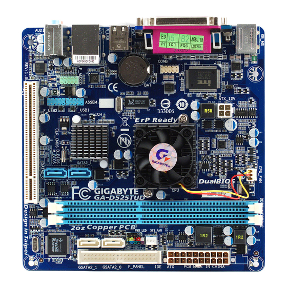
Page 7: Ga-D525Tud/Ga-D425Tud Motherboard Layout
GA-D525TUD/GA-D425TUD Motherboard Layout KB_MS ATX_12V CPU_FAN GA-D525TUD/ GA-D425TUD Intel Atom ™ D525 j ® ™ Intel Atom D425 k ® F_PANEL R_USB Realtek RTL8111E USB_LAN Intel ® NM10 F_USB1 AUDIO B_BIOS F_AUDIO F_USB2 CODEC GIGABYTE M_BIOS SATA2 Only for GA-D525TUD. -
Page 8: Ga-D525Tud/Ga-D425Tud Motherboard Block Diagram
GA-D525TUD/GA-D425TUD Motherboard Block Diagram CPU CLK+/- (200 MHz) Intel ® DDR3 800 MHz ™ Atom D-Sub Memory Interface RJ45 Dual BIOS Realtek RTL8111E PCIe CLK (100 MHz) 2 SATA 3Gb/s Intel NM10 ® PCI Express Bus 8 USB 2.0/1.1 GIGABYTE... -
Page 9: Chapter 1 Hardware Installation
Chapter 1 Hardware Installation Installation Precautions The motherboard contains numerous delicate electronic circuits and components which can become damaged as a result of electrostatic discharge (ESD). Prior to installation, carefully read the user's manual and follow these procedures: • Prior to installation, do not remove or break motherboard S/N (Serial Number) sticker or warranty sticker provided by your dealer. -
Page 10: Product Specifications
2 x 1.5V DDR3 DIMM sockets supporting up to 4 GB of system memory (Note 2) Support for DDR3 800 MHz memory modules (Go to GIGABYTE's website for the latest supported memory speeds and memory modules.) Audio Realtek ALC888B codec High Definition Audio (Note 3) 2/4/5.1/7.1-channel 1 xRealtek RTL8111E chip (10/100/1000 Mbit) ... - Page 11 Back Panel 1 x PS/2 keyboard port 1 x PS/2 mouse port Connectors 1 x parallel port 1 x serial port 1 x D-Sub port 4 x USB 2.0/1.1 ports 1 x RJ-45 port ...
-
Page 12: Installing The Memory
• Make sure that the motherboard supports the memory. It is recommended that memory of the same capacity, brand, speed, and chips be used. (Go to GIGABYTE's website for the latest supported memory speeds and memory modules.) • Always turn off the computer and unplug the power cord from the power outlet before installing the memory to prevent hardware damage. -
Page 13: Back Panel Connectors
Back Panel Connectors PS/2 Keyboard and PS/2 Mouse Port Use the upper port (green) to connect a PS/2 mouse and the lower port (purple) to connect a PS/2 key- board. Parallel Port Use the parallel port to connect devices such as a printer, scanner and etc. The parallel port is also called a printer port. - Page 14 Line In Jack (Blue) The default line in jack. Use this audio jack for line in devices such as an optical drive, walkman, etc. Line Out Jack (Green) The default line out jack. Use this audio jack for a headphone or 2-channel speaker. This jack can be used to connect front speakers in a 4/5.1/7.1-channel audio configuration.
-
Page 15: Internal Connectors
Internal Connectors ATX_12V PWR_LED CPU_FAN F_PANEL SYS_FAN F_AUDIO F_USB1/F_USB2 SATA2_0/1 COMB GSATA2_0/1 Read the following guidelines before connecting external devices: • First make sure your devices are compliant with the connectors you wish to connect. • Before installing the devices, be sure to turn off the devices and your computer. Unplug the power cord from the power outlet to prevent damage to the devices. - Page 16 1/2) ATX_12V/ATX (2x2 12V Power Connector and 2x10 Main Power Connector) With the use of the power connector, the power supply can supply enough stable power to all the components on the motherboard. Before connecting the power connector, first make sure the power supply is turned off and all devices are properly installed.
- Page 17 3/4) CPU_FAN/SYS_FAN (Fan Headers) The motherboard has a 3-pin CPU fan header (CPU_FAN) and a 3-pin (SYS_FAN) system fan header. Most fan headers possess a foolproof insertion design. When connecting a fan cable, be sure to connect it in the correct orientation (the black connector wire is the ground wire). The motherboard supports CPU fan speed control, which requires the use of a CPU fan with fan speed control design.
- Page 18 7) GSATA2_0/1 (SATA 3Gb/s Connectors, Controlled by GIGABYTE SATA2) The SATA connectors conform to SATA 3Gb/s standard and are compatible with SATA 1.5Gb/s standard. Each SATA connector supports a single SATA device. The GIGABYTE SATA2 controller supports RAID 0, RAID 1, and JBOD. Refer to Chapter 5, "Configuring SATA Hard Drive(s)," for instructions on configuring a RAID array.
-
Page 19: Battery
8) PWR_LED (System Power LED Header) This header can be used to connect a system power LED on the chassis to indicate system power status. The LED is on when the system is operating. The LED keeps blinking when the system is in S1 sleep state. - Page 20 10) F_PANEL (Front Panel Header) Connect the power switch, reset switch, and system status indicator on the chassis to this header ac- cording to the pin assignments below. Note the positive and negative pins before connecting the cables. Power Reset RES+ Switch RES-...
- Page 21 11) F_AUDIO (Front Panel Audio Header) The front panel audio header supports Intel High Definition audio (HD) and AC'97 audio. You may connect your chassis front panel audio module to this header. Make sure the wire assignments of the module con- nector match the pin assignments of the motherboard header. Incorrect connection between the module connector and the motherboard header will make the device unable to work or even damage it. For HD Front Panel Audio: For AC'97 Front Panel Audio: Pin No. Definition...
- Page 22 13) COMB (Serial Port Header) The COM header can provide one serial port via an optional COM port cable. For purchasing the op- tional COM port cable, please contact the local dealer. Pin No. Definition 10 9 NDCD- NSIN NSOUT NDTR- NDSR- NRTS- NCTS-...
-
Page 23: Chapter 2 Bios Setup
To see more advanced BIOS Setup menu options, you can press <Ctrl> + <F1> in the main menu of the BIOS Setup program. To upgrade the BIOS, use either the GIGABYTE Q-Flash or @BIOS utility. Q-Flash allows the user to quickly and easily upgrade or back up BIOS without entering the operating •... -
Page 24: Startup Screen
Startup Screen The following screens may appear when the computer boots. Award Modular BIOS v6.00PG, An Energy Star Ally Copyright (C) 1984-2010, Award Software, Inc. D525TUD E10c Motherboard Model BIOS Version Function Keys <DEL>: BIOS Setup <F9>: XpressRecovery2 <F12>: Boot Menu <End>: Qflash 06/25/2010-Pine-7A89SG03C-00 Function Keys: <DEL>: BIOS SETUP... -
Page 25: The Main Menu
The Main Menu Once you enter the BIOS Setup program, the Main Menu (as shown below) appears on the screen. Use ar- row keys to move among the items and press <Enter> to accept or enter a sub-menu. (Sample BIOS Version: GA-D525TUD E10c) CMOS Setup Utility-Copyright (C) 1984-2010 Award Software MB Intelligent Tweaker(M.I.T.) Load Fail-Safe Defaults... -
Page 26: Standard Cmos Features
The Functions of the <F11> and <F12> keys (For the Main Menu Only) F11: Save CMOS to BIOS This function allows you to save the current BIOS settings to a profile. You can create up to 8 profiles (Profile 1-8) and name each profile. First enter the profile name (to erase the default profile name, use the SPACE key) and then press <Enter> to complete. F12: Load CMOS from BIOS If your system becomes unstable and you have loaded the BIOS default settings, you can use this function to load the BIOS settings from a profile created before, without the hassles of reconfiguring the BIOS settings. First select the profile you wish to load, then press <Enter> to complete. -
Page 27: Mb Intelligent Tweaker(M.i.t.)
MB Intelligent Tweaker(M.I.T.) CMOS Setup Utility-Copyright (C) 1984-2010 Award Software MB Intelligent Tweaker(M.I.T.) Item Help CPU Host Clock Control [Disabled] Menu Level x CPU Host Frequency (Mhz) PCI Express Frequency (Mhz) [Auto] ******** Mother Board Voltage Control ******** Voltage Types Normal Current -----------------------------------------------------------------------------... - Page 28 ******** Mother Board Voltage Control ******** >>> CPU CPU Vcore The default is Auto. >>> DRAM DRAM Voltage The default is Auto. BIOS Setup - 28 -...
-
Page 29: Standard Cmos Features
Standard CMOS Features CMOS Setup Utility-Copyright (C) 1984-2010 Award Software Standard CMOS Features Item Help Date (mm:dd:yy) Mon, Jun 21 2010 Menu Level Time (hh:mm:ss) 22:31:24 IDE Channel 0 Master [None] IDE Channel 1 Master [None] IDE Channel 2 Master [None] ... - Page 30 The following fields display your hard drive specifications. If you wish to enter the parameters manually, refer to the information on the hard drive. Capacity Approximate capacity of the currently installed hard drive. Cylinder Number of cylinders. Head Number of heads. Precomp Write precompensation cylinder. Landing Zone Landing zone. Sector Number of sectors. Halt On Allows you to determine whether the system will stop for an error during the POST.
-
Page 31: Advanced Bios Features
Advanced BIOS Features CMOS Setup Utility-Copyright (C) 1984-2010 Award Software Advanced BIOS Features Item Help Hard Disk Boot Priority [Press Enter] Menu Level Quick Boot [Disabled] First Boot Device [Hard Disk] Second Boot Device [CDROM] Third Boot Device [USB-FDD] Password Check [Setup]... -
Page 32: Init Display First
CPU Multi-Threading Allows you to determine whether to enable all CPU cores and multi-threading function when using an Intel CPU that supports multi-core technology. This feature only works for operating systems that support multi-processor mode. Enabled Enables all CPU cores and multi-threading capability. (Default) Disabled Enables only one CPU core. -
Page 33: Integrated Peripherals
Integrated Peripherals CMOS Setup Utility-Copyright (C) 1984-2010 Award Software Integrated Peripherals Item Help SATA AHCI Mode [IDE] Menu Level Azalia Codec [Auto] Onboard H/W LAN [Enabled] Green LAN [Disabled] SMART LAN [Press Enter] Onboard LAN Boot ROM [Disabled] Onboard SATA/IDE Device [Enabled] Onboard SATA/IDE Ctrl Mode... -
Page 34: Onboard Lan Boot Rom
Allows you to decide whether to activate the boot ROM integrated with the onboard LAN chip. (Default: Disabled) Onboard SATA/IDE Device (GIGABYTE SATA2, IDE and GSATA2_0/1 Connectors) Enables or disables the IDE and SATA controllers integrated in the GIGABYTE SATA2 chip. (Default: Enabled) BIOS Setup... -
Page 35: Onboard Parallel Port
Onboard SATA/IDE Ctrl Mode (GIGABYTE SATA2, IDE and GSATA2_0/1 Connectors) Enables or disables RAID for the SATA controller integrated in the GIGABYTE SATA2 chip or configures the SATA controller to AHCI mode. IDE Disables RAID for the SATA controller and configures the SATA controller to IDE mode. (Default) AHCI Configures the SATA controller to AHCI mode. Advanced Host Controller Interface (AHCI) is an interface specification that allows the storage driver to enable advanced Serial ATA features such as Native Command Queuing and hot plug. RAID/IDE Enables RAID for the SATA controller; the IDE controller still operates in IDE mode. -
Page 36: Power Management Setup
Power Management Setup CMOS Setup Utility-Copyright (C) 1984-2010 Award Software Power Management Setup Item Help ACPI Suspend Type [S3(STR)] Menu Level Soft-Off by PWR-BTTN [Instant-Off] PME Event Wake Up [Enabled] Power On by Ring [Enabled] Resume by Alarm [Disabled] Date (of Month) Alarm Everyday Time (hh:mm:ss) Alarm... - Page 37 Resume by Alarm Determines whether to power on the system at a desired time. (Default: Disabled) If enabled, set the date and time as following: Date (of Month) Alarm: Turn on the system at a specific time on each day or on a specific day in a month. Time (hh: mm: ss) Alarm: Set the time at which the system will be powered on automatically. Note: When using this function, avoid inadequate shutdown from the operating system or removal of the AC power, or the settings may not be effective.
-
Page 38: Pnp/Pci Configurations
PnP/PCI Configurations CMOS Setup Utility-Copyright (C) 1984-2010 Award Software PnP/PCI Configurations Item Help PCI1 IRQ Assignment [Auto] Menu Level higf : Move Enter: Select +/-/PU/PD: Value F10: Save ESC: Exit F1: General Help F5: Previous Values F6: Fail-Safe Defaults F7: Optimized Defaults PCI1 IRQ Assignment Auto BIOS auto-assigns IRQ to the first PCI slot. (Default) -
Page 39: Pc Health Status
PC Health Status CMOS Setup Utility-Copyright (C) 1984-2010 Award Software PC Health Status Item Help Reset Case Open Status [Disabled] Menu Level Case Opened Vcore 1.220V DDR15V 1.504V +3.3V 3.392V +12V 12.048V Current CPU Temperature Current CPU FAN Speed 3375 RPM Current SYSTEM FAN Speed 0 RPM... -
Page 40: Load Fail-Safe Defaults
2-10 Load Fail-Safe Defaults CMOS Setup Utility-Copyright (C) 1984-2010 Award Software MB Intelligent Tweaker(M.I.T.) Load Fail-Safe Defaults Standard CMOS Features Load Optimized Defaults Advanced BIOS Features Set Supervisor Password Integrated Peripherals Set User Password Power Management Setup Save &... -
Page 41: Set Supervisor/User Password
2-12 Set Supervisor/User Password CMOS Setup Utility-Copyright (C) 1984-2010 Award Software MB Intelligent Tweaker(M.I.T.) Load Fail-Safe Defaults Standard CMOS Features Load Optimized Defaults Advanced BIOS Features Set Supervisor Password Integrated Peripherals Set User Password Power Management Setup Save &... -
Page 42: Save & Exit Setup
2-13 Save & Exit Setup CMOS Setup Utility-Copyright (C) 1984-2010 Award Software MB Intelligent Tweaker(M.I.T.) Load Fail-Safe Defaults Standard CMOS Features Load Optimized Defaults Advanced BIOS Features Set Supervisor Password Save to CMOS and EXIT (Y/N)? Y Integrated Peripherals Set User Password ... -
Page 43: Chapter 3 Drivers Installation
Chapter 3 Drivers Installation • Before installing the drivers, first install the operating system. • After installing the operating system, insert the motherboard driver disk into your optical drive. The driver Autorun screen is automatically displayed which looks like that shown in the screen shot below. (If the driver Autorun screen does not appear automatically, go to My Computer, double-click the optical drive and execute the Run.exe program.) Installing Chipset Drivers After inserting the driver disk, "Xpress Install"... -
Page 44: Application Software
Application Software This page displays all the utilities and applications that GIGABYTE develops and some free software. You can click the Install button on the right of an item to install it. Technical Manuals This page provides GIGABYTE's application guides, content descriptions for this driver disk, and the mother- board manuals. -
Page 45: Contact
Contact For the detailed contact information of the GIGABYTE Taiwan headquarter or worldwide branch offices, click the URL on this page to link to the GIGABYTE website. System This page provides the basic system information. - 45 - Drivers Installation... -
Page 46: Download Center
The latest version of the BIOS, drivers, or applications will be displayed. New Utilities This page provides a quick link to GIGABYTE's lately developed utilities for users to install. You can click the Install button on the right of an item to install it. -
Page 47: Chapter 4 Unique Features
Chapter 4 Unique Features Xpress Recovery2 Xpress Recovery2 is a utility that allows you to quickly compress and back up your system data and perform restoration of it. Supporting NTFS, FAT32, and FAT16 file systems, Xpress Recovery2 can back up data on PATA and SATA hard drives and restore it. - Page 48 Step 3: Step 4: When partitioning your hard drive, make sure to After the operating system is installed, right-click the Computer icon on your desktop and select leave unallocated space (10 GB or more is recom- mended; actual size requirements vary, depending Manage.
- Page 49 D. Using the Restore Function in Xpress Recovery2 Select RESTORE to restore the backup to your hard drive in case the system breaks down. The RESTORE option will not be present if no backup is created before. E. Removing the Backup Step 1: Step 2: If you wish to remove the backup file, select...
-
Page 50: Bios Update Utilities
BIOS Update Utilities GIGABYTE motherboards provide two unique BIOS update tools, Q-Flash and @BIOS . GIGABYTE ™ ™ Q-Flash and @BIOS are easy-to-use and allow you to update the BIOS without the need to enter MS-DOS mode. Additionally, this motherboard features the DualBIOS design, which enhances protection for the ™... - Page 51 B. Updating the BIOS When updating the BIOS, choose the location where the BIOS file is saved. The following procedure as- sumes that you save the BIOS file to a floppy disk. Step 1: 1. Insert the USB flash drive containing the BIOS file into your system. In the main menu of Q-Flash, use the up or down arrow key to select Update BIOS from Drive and press <Enter>. •...
- Page 52 Step 4: Press <Esc> and then <Enter> to exit Q-Flash and reboot the system. As the system boots, you should see the new BIOS version is present on the POST screen. Step 5: During the POST, press <Delete> to enter BIOS Setup. Select Load Optimized Defaults and press <Enter> to load BIOS defaults.
-
Page 53: Updating The Bios With The @Bios Utility
BIOS or a system that is unable to start. Do not use the G.O.M. (GIGABYTE Online Management) function when using @BIOS. GIGABYTE product warranty does not cover any BIOS damage or system failure resulting from an inad- equate BIOS flashing. -
Page 54: Easytune 6
EasyTune 6 GIGABYTE's EasyTune 6 is a simple and easy-to-use interface that allows users to fine-tune their system settings or do overclock/overvoltage in Windows environment. The user-friendly EasyTune 6 interface also includes tabbed pages for CPU and memory information, letting users read their system-related information without the need to install additional software. The EasyTune 6 Interface... -
Page 55: Q-Share
Q-Share, you are able to share your data with computers on the same network, making full use of Internet resources. Directions for using Q-Share After installing Q-Share from the motherboard driver disk, go to Start>All Programs>GIGABYTE>Q-Share. exe to launch the Q-Share tool. Find the Q-Share icon in the notification area and right-click on this icon to configure the data sharing settings. -
Page 56: Smart Recovery
SMART Recovery With SMART Recovery, users can quickly create backups of changed data files or copy files from a spe- (Note 1) cific backup on PATA and SATA hard drives (partitioned on NTFS file system) in Windows Vista. Instructions: In the main menu, click the Config button to open the Smart Recov- ery Preference dialog box. The Smart Recovery Preference dialog box: Button Function Enable Enables automatic daily backup (Note 2) Schedule Sets a daily backup schedule Capacity... -
Page 57: Auto Green
Auto Green Auto Green is an easy-to-use tool that provides users with simple options to enable system power savings via a Bluetooth cell phone. When the phone is out of the range of the computer's Bluetooth receiver, the sys- tem will enter the specified power saving mode. The Configuration dialog box: First, you have to set your Bluetooth cell phone as a portable key. - Page 58 Unique Features - 58 -...
-
Page 59: Chapter 5 Appendix
Chapter 5 Appendix Configuring SATA Hard Drive(s) To configure SATA hard drive(s), follow the steps below: A. Install SATA hard drive(s) in your computer. B. Configure SATA controller mode in BIOS Setup. C. Configure a RAID array in RAID BIOS. (Note 1) D. Make a floppy disk containing the SATA RAID/AHCI driver for Windows XP. (Note 2) E. Install the SATA RAID/AHCI driver and operating system. (Note 2) Before you begin Please prepare:... -
Page 60: Configuring Gigabyte Sata2 Sata Controller
Attach one end of the SATA signal cable to the rear of the SATA hard drive and the other end to available SATA port on the motherboard. On this motherboard, the GSATA2_0 and GSATA2_1 ports are supported by the GIGABYTE SATA2 SATA controller. Then connect the power connector from your power supply to the hard drive. - Page 61 After the POST memory test begins and before the operating system boot begins, look for a message which says "Press <Ctrl-G> to enter RAID Setup Utility" (Figure 2). Press <Ctrl> + <G> to enter the RAID setup util- ity. GIGABYTE Technology Corp. PCI Express to SATAII HOST Controller ROM v1.07.06 Copyright (C) 2005-2009 Gigabyte Technology Corp. (http://www.gigabyte.com)
- Page 62 In the main screen, press <Enter> on the Create RAID Disk Drive item. Then the Create New RAID screen appears (Figure 4). Gigabyte Technology Corp. RAID Setup Utility v1.07.06 [ Create New RAID ] [ Hard Disk Drive List ]...
- Page 63 4. Set Block Size (RAID 0 only): Under the Block item, use the up or down arrow key to select the stripe block size (Figure 6), ranging from 4 KB to 128 KB. Press <Enter>. Gigabyte Technology Corp. RAID Setup Utility v1.07.06 [ Create New RAID ]...
- Page 64 When finished, the new RAID array will be displayed in the RAID Disk Drive List block (Figure 8). Gigabyte Technology Corp. RAID Setup Utility v1.07.06 [ Main Menu ] [ Hard Disk Drive List ] Create RAID Disk Drive Model Name Capacity Type/Status Delete RAID Disk Drive HDD0: ST3120026AS 120 GB...
- Page 65 7. Save and Exit Setup: After configuring the RAID array, select the Save And Exit Setup item in the main screen to save your settings before exiting the RAID BIOS utility, then press <Y> (Figure 10). Gigabyte Technology Corp. RAID Setup Utility v1.07.06 [ Main Menu ] [ Hard Disk Drive List ]...
-
Page 66: Making A Sata Raid/Ahci Driver Diskette
3: Insert the blank formatted disk. Depending on the operating system to be installed, select the controller driver by pressing the corresponding letter from the menu and press <Enter>. For example, from the menu in Figure 2, • For the GIGABYTE SATA2, select 3) GIGABYTE GSATA driver for 32bit system for Windows 32-bit operating system. Your system will then automatically copy the driver files to the floppy disk. Press any key to exit when finished. -
Page 67: Installing The Sata Raid/Ahci Driver And Operating System
Press F6 if you need to install a third party SCSI or RAID driver. Figure 1 Step 2: Insert the floppy disk containing the SATA RAID/AHCI driver and press <S>. Then a controller menu similar to Figure 2 below will appear. Select RAID/AHCI Driver for GIGABYTE GBB36X Controller (x32) and press <Enter>. Windows Setup You have chosen to configure a SCSI Adapter for use with Windows, using a device support disk provided by an adapter manufacturer. - Page 68 B. Installing Windows Vista (The procedure below assumes that only one RAID array exists in your system.) Step 1: Restart your system to boot from the Windows Vista setup disk and perform standard OS installation steps. When a screen similar to that below appears (RAID/AHCI hard drive(s) will not be detected at this stage), select Load Driver (Figure 3).
- Page 69 Step 3: When a screen as shown in Figure 5 appears, select GIGABYTE GBB36X Controller and click Next. Figure 5 Step 4: After the driver is loaded, select the RAID/AHCI drive(s) where you want to install the operating system and then click Next to continue the OS installation (Figure 6).
- Page 70 Turn off your computer and replace the failed hard drive with a new one. Use either the RAID setup utility or the GIGABYTE RAID CONFIGURER utility in the operating system to perform the rebuild. • Rebuilding with the RAID setup utility Step 1: When the message "Press <Ctrl-G>...
- Page 71 • Rebuilding in the operating system Make sure the GIGABYTE SATA2 SATA controller driver has been installed from the motherboard driver disk. Launch the GIGABYTE RAID CONFIGURER from All Programs in the Start menu. Step 2: When the Rebuilding RAID Wizard appears, click Next.
-
Page 72: Configuring Audio Input And Output
Configuring Audio Input and Output 5-2-1 Configuring 2/4/5.1/7.1-Channel Audio The motherboard provides three audio jacks on the back panel which support 2/4/5.1/7.1 -channel audio. The picture to the (Note) right shows the default audio jack assignments. Line In The integrated HD (High Definition) audio provides jack retask- Front Speaker Out ing capability that allows the user to change the function for each jack through the audio driver. - Page 73 The pictures to the right show the 7.1-channel speak- 7.1-Channel Speakers: er configurations. Front Speaker Rear Speaker Center/Sub- woofer Speaker Out Side Speaker Step 2: Connect an audio device to an audio jack. The The cur- rent connected device is dialog box appears. Select the device according to the type of device you connect.
- Page 74 C. Activating an AC'97 Front Panel Audio Module If your chassis provides an AC'97 front panel audio mod- ule, to activate the AC'97 functionality, click the tool icon on the Speaker Configuration tab. On the Connector Settings dialog box, select the Disable front panel jack detection check box.
-
Page 75: Configuring Microphone Recording
5-2-2 Configuring Microphone Recording Step 1: After installing the audio driver, the HD Audio Manager icon will appear in the notification area. Double-click the icon to access the HD Audio Manager. Step 2: Connect your microphone to the Mic in jack (pink) on the back panel or the Mic in jack (pink) on the front panel. Then configure the jack for microphone function- ality. - Page 76 Step 4: To raise the recording and playback volume for the microphone, click the Microphone Boost icon the right of the Recording Volume slider and set the Microphone Boost level. Step 5: After completing the settings above, click Start, point to All Programs, point to Accessories, and then click Sound Recorder to begin the sound recording.
-
Page 77: Using The Sound Recorder
Step 3: When the Stereo Mix item appears, right-click on this item and select Enable. Then set it as the default de- vice. Step 4: Now you can access the HD Audio Manager to config- ure Stereo Mix and use Sound Recorder to record the sound. -
Page 78: Troubleshooting
New Hardware Wizard appears, click Cancel. Then install the onboard HD audio driver from the motherboard driver disk or download the audio driver from GIGABYTE's website to install. For more details, go to the Support&Downloads\Motherboards\FAQ page on our website and search for "onboard HD audio driver."... -
Page 79: Troubleshooting Procedure
5-3-2 Troubleshooting Procedure If you encounter any troubles during system startup, follow the troubleshooting procedure below to solve the problem. START Turn off the power. Remove all peripherals, connecting cables, and power cord etc. Make sure the motherboard does not short-circuit with the chassis or Isolate the short circuit. - Page 80 The power supply, CPU or When the computer is turned on, is the CPU cooler running? CPU socket might fail. The problem is verified and solved. The graphics card, expansion slot, or monitor Check if there is display on your monitor. might fail. The problem is verified and solved. Turn off the computer. Plug in the keyboard and mouse and restart the computer.
-
Page 81: Regulatory Statements
Contravention will be prosecuted. We believe that the information contained herein was accurate in all respects at the time of printing. GIGABYTE cannot, however, assume any responsibility for errors or omissions in this text. Also note that the informa- tion in this document is subject to change without notice and should not be construed as a commitment by GIGABYTE. - Page 82 Finally, we suggest that you practice other environmentally friendly actions by understanding and using the energy-saving features of this product (where applicable), recycling the inner and outer packaging (including shipping containers) this product was delivered in, and by disposing of or recycling used batteries properly. With your help, we can reduce the amount of natural resources needed to produce electrical and electronic equipment, minimize the use of landfills for the disposal of "end of life" products, and generally improve our quality of life by ensuring that potentially hazardous substances are not released into the environment and...
- Page 83 - 83 - Appendix...
- Page 84 Appendix - 84 -...
- Page 85 - 85 - Appendix...
- Page 86 Appendix - 86 -...
- Page 87 Shenyang http://rma.gigabyte.us Web address: http://latam.giga-byte.com TEL: +86-24-83992901 • Giga-Byte SINGAPORE PTE. LTD. - Singapore FAX: +86-24-83992909 • GIGABYTE TECHNOLOGY (INDIA) LIMITED - India WEB address : http://www.gigabyte.sg • Thailand WEB address : http://www.gigabyte.in WEB address : http://th.giga-byte.com • Saudi Arabia •...
- Page 88 WEB address : http://www.gigabyte.com.gr WEB address : http://www.gigabyte.kz • Czech Republic You may go to the GIGABYTE website, select your language WEB address : http://www.gigabyte.cz in the language list on the top right corner of the website. • GIGABYTE Global Service System...
Need help?
Do you have a question about the GA-D425TUD and is the answer not in the manual?
Questions and answers