
Related Manuals for ASROCK 970 Pro3 R2.0


Summary of Contents for ASROCK 970 Pro3 R2.0
-
Page 1: User Manual
970 Pro3 R2.0 User Manual Version 1.0 Published September 2012 Copyright©2012 ASRock INC. All rights reserved. -
Page 2: Copyright Notice
ASRock. ASRock assumes no responsibility for any errors or omissions that may appear in this manual. With respect to the contents of this manual, ASRock does not provide warranty of any kind, either expressed or implied, including but not limited to the implied warran- ties or conditions of merchantability or fitness for a particular purpose. -
Page 3: Table Of Contents
Expansion Slots (PCI and PCI Express Slots) ......21 CrossFireX and Quad CrossFireX Operation Guide .... 22 Surround Display Information ............ 25 ASRock Smart Remote Installation Guide ......... 26 Jumpers Setup ................28 Onboard Headers and Connectors ........29 2.10 Serial ATA3 (SATA3) Hard Disks Installation ...... - Page 4 3. UEFI SETUP UTILITY ..........41 Introduction ................41 3.1.1 UEFI Menu Bar ..............41 3.1.2 Navigation Keys ............... 42 Main Screen ................43 OC Tweaker Screen..............44 Advanced Screen ..............48 3.4.1 CPU Configuration ............49 3.4.2 North Bridge Configuration ..........50 3.4.3 South Bridge Configuration ..........
-
Page 5: Introduction
1. Introduction Thank you for purchasing ASRock 970 Pro3 R2.0 motherboard, a reliable moth- erboard produced under ASRock’s consistently stringent quality control. It delivers excellent performance with robust design conforming to ASRock’s commitment to quality and endurance. In this manual, chapter 1 and 2 contain introduction of the motherboard and step- by-step guide to the hardware installation. -
Page 6: Specifications
1.2 Specifications Platform - ATX Form Factor - All Solid Capacitor design - Support for Socket AM3+ processors - Support for Socket AM3 processors: AMD Phenom II X6 / X4 / X3 / X2 (except 920 / 940) / Athlon II X4 / X3 / X2 / Sempron processors - Supports 8-Core CPU - Supports UCC feature (Unlock CPU Core) (see CAUTION 1) - Page 7 Rear Panel I/O I/O Panel - 1 x PS/2 Mouse Port - 1 x PS/2 Keyboard Port - 6 x Ready-to-Use USB 2.0 Ports - 2 x Ready-to-Use USB 3.0 Ports - 1 x RJ-45 LAN Port with LED (ACT/LINK LED and SPEED LED) - HD Audio Jack: Side Speaker/Rear Speaker/Central/Bass/ Line in/Front Speaker/Microphone...
- Page 8 Certifications - FCC, CE, WHQL - ErP/EuP Ready (ErP/EuP ready power supply is required) * For detailed product information, please visit our website: http://www.asrock.com WARNING Please realize that there is a certain risk involved with overclocking, including adjusting the setting in the BIOS, applying Untied Overclocking Technology, or using third-party overclocking tools.
- Page 9 ® ® der Windows 8 / 7 / Vista / XP. For Windows 64-bit OS with 64-bit CPU, there is no such limitation. You can use ASRock ® XFast RAM to utilize the memory that Windows cannot use. ® ®...
-
Page 10: Unique Features
OS 32-bit CPU. ASRock Instant Boot ASRock Instant Boot allows you to turn on your PC in just a few seconds, provides a much more efficient way to save energy, time, money, and improves system running speed for your sys- tem. - Page 11 ASRock XFast RAM ASRock XFast RAM is a new function that is included into AS- Rock Extreme Tuning Utility (AXTU). It fully utilizes the memory ® space that cannot be used under Windows OS 32-bit CPU.
- Page 12 DHCP configured computer in order to enable this function. ASRock On/Off Play Technology ASRock On/Off Play Technology allows users to enjoy the great audio experience from the portable audio devices, such like MP3 player or mobile phone to your PC, even when the PC is turned off (or in ACPI S5 mode)! This motherboard also provides a free 3.5mm audio cable (optional) that ensures users the most...
- Page 13 Function, the computer will power on automatically to dehumidi- fy the system after entering S4/S5 state. ASRock Fast Boot With ASRock’s exclusive Fast Boot technology, it takes less ® than 1.5 seconds to logon to Windows 8 from a cold boot. No more waiting! The speedy boot will completely change your user experience and behavior.
- Page 14 ASRock Good Night LED ASRock Good Night LED technology can offer you a better environment by extinguishing the unessential LED. By enabling Good Night LED in BIOS, the Power / HDD / LAN LED will be switched off when system is on. Not only this, Good night LED will automatically switch off Power and Keyboard LED when the system enters into Standby / Hibernation mode as well.
-
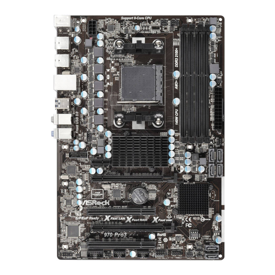
Page 15: Motherboard Layout
1.3 Motherboard Layout Support 8-Core CPU CPU_FAN2 CPU_FAN1 USB 2.0 T: USB0 B: USB1 USB 2.0 T: USB2 B: USB3 USB 2.0 T: USB4 B: USB5 USB 3.0 T: USB0 B: USB1 CHA_FAN1 PWR_FAN1 USB3_2_3 Chipset PCIE1 PCIE2 CMOS BATTERY SB950 AUDIO CODEC... -
Page 16: I/O Panel
1.4 I/O Panel PS/2 Mouse Port (Green) Microphone (Pink) LAN RJ-45 Port USB 3.0 Port (USB3_0_1) Side Speaker (Gray) USB 2.0 Port (USB_4_5) Rear Speaker (Black) USB 2.0 Port (USB_2_3) Central / Bass (Orange) USB 2.0 Port (USB_0_1) Line In (Light Blue) PS/2 Keyboard Port (Purple) ** 7 Front Speaker (Lime) -
Page 17: Installation
2. Installation This is an ATX form factor motherboard. Before you install the motherboard, study the configuration of your chassis to ensure that the motherboard fits into it. Pre-installation Precautions Take note of the following precautions before you install motherboard components or change any motherboard settings. -
Page 18: Cpu Installation
2.1 CPU Installation Step 1. Unlock the socket by lifting the lever up to a 90 angle. Step 2. Position the CPU directly above the socket such that the CPU corner with the golden triangle matches the socket corner with a small triangle. Step 3. -
Page 19: Installation Of Memory Modules (Dimm)
2.3 Installation of Memory Modules (DIMM) This motherboard provides four 240-pin DDR3 (Double Data Rate 3) DIMM slots, and supports Dual Channel Memory Technology. For dual channel configuration, you always need to install identical (the same brand, speed, size and chip-type) DDR3 DIMM pair in the slots. -
Page 20: Installing A Dimm
Installing a DIMM Please make sure to disconnect power supply before adding or removing DIMMs or the system components. Step 1. Unlock a DIMM slot by pressing the retaining clips outward. Step 2. Align a DIMM on the slot such that the notch on the DIMM matches the break on the slot. -
Page 21: Expansion Slots (Pci And Pci Express Slots)
2.4 Expansion Slots (PCI and PCI Express Slots) There are 2 PCI slots and 3 PCI Express slots on this motherboard. PCI Slots: PCI slots are used to install expansion cards that have the 32-bit PCI interface. PCIE Slots: PCIE1 (PCIE x1 slot) is used for PCI Express cards with x1 lane width cards, such as Gigabit LAN card and SATA2 card. -
Page 22: Crossfirex Tm And Quad Crossfirex Tm Operation Guide
2.5 CrossFireX and Quad CrossFireX Operation Guide This motherboard supports CrossFireX and Quad CrossFireX feature. CrossFireX technology offers the most advantageous means available of combining multiple high performance Graphics Processing Units (GPU) in a single PC. Combining a range of different operating modes with intelligent software design and an innovative interconnect mechanism, CrossFireX enables the highest possible level of performance and image quality in any 3D application. - Page 23 Step 2. Connect two Radeon graphics cards by installing a CrossFire Bridge on the CrossFire Bridge Interconnects on the top of the Radeon graphics cards. (The CrossFire Bridge is provided with the graphics card you pur- chase, not bundled with this motherboard. Please refer to your graphics card vendor for details.) CrossFire Bridge Step 3.
-
Page 24: Driver Installation And Setup
2.5.2 Driver Installation and Setup Step 1. Power on your computer and boot into OS. Step 2. Remove the AMD driver if you have any VGA driver installed in your sys- tem. The Catalyst Uninstaller is an optional download. We recommend using this utility to uninstall any previously installed Catalyst drivers prior to installation. -
Page 25: Surround Display Information
Although you have selected the option “Enable CrossFire ”, the Cross- FireX function may not work actually. Your computer will automatically reboot. After restarting your computer, please confirm whether the option “Enable CrossFire ” in “ATI Catalyst Control Center” is selected or not; if not, please select it again, and then you are able to enjoy the benefit of CrossFireX feature. -
Page 26: Asrock Smart Remote Installation Guide
2.7 ASRock Smart Remote Installation Guide ASRock Smart Remote is only used for ASRock motherboard with CIR header. Please refer to below procedures for the quick installation and usage of ASRock Smart Remote. Step1. Find the CIR header located next to the USB 2.0 header on ASRock... - Page 27 The Multi-Angle CIR Receiver does not support Hot-Plug function. Please install it before you boot the system. * ASRock Smart Remote is only supported by some of ASRock motherboards. Please refer to ASRock website for the motherboard support list: http://www.asrock.com...
-
Page 28: Jumpers Setup
2.8 Jumpers Setup The illustration shows how jumpers are setup. When the jumper cap is placed on pins, the jumper is “Short”. If no jumper cap is placed on pins, the jumper is “Open”. The illustration shows a 3-pin jumper whose pin1 and pin2 are “Short”... -
Page 29: Onboard Headers And Connectors
2.9 Onboard Headers and Connectors Onboard headers and connectors are NOT jumpers. Do NOT place jumper caps over these headers and connectors. Placing jumper caps over the headers and connectors will cause permanent damage of the motherboard! Serial ATA3 Connectors These six Serial ATA3 (SATA3) connectors support (SATA3_1: see p.15, No. - Page 30 Infrared Module Header This header supports an IRTX +5VSB optional wireless transmitting (5-pin IR1) DUMMY and receiving infrared module. (see p.15 No. 27) IRRX Consumer Infrared Module Header This header can be used to connect the remote (4-pin CIR1) controller receiver. (see p.15 No.
- Page 31 PWRBTN (Power Switch): Connect to the power switch on the chassis front panel. You may con- figure the way to turn off your system using the power switch. RESET (Reset Switch): Connect to the reset switch on the chassis front panel. Press the reset switch to restart the computer if the computer freezes and fails to per- form a normal restart.
- Page 32 CPU Fan Connectors Please connect the CPU fan FAN_SPEED_CONTROL cable to the connector and (4-pin CPU_FAN1) CPU_FAN_SPEED +12V match the black wire to the (see p.15 No. 5) ground pin. 1 2 3 4 Though this motherboard provides 4-Pin CPU fan (Quiet Fan) support, the 3-Pin CPU fan still can work successfully even without the fan speed control function.
-
Page 33: Serial Port Header
Serial port Header This COM1 header supports a serial port module. (9-pin COM1) (see p.15 No.28) HDMI_SPDIF Header HDMI_SPDIF header, providing SPDIF audio output to HDMI (2-pin HDMI_SPDIF1) VGA card, allows the system to see p.15 No. 29) connect HDMI Digital TV/ projector/LCD devices. -
Page 34: Serial Ata3 (Sata3) Hard Disks Installation
2.10 Serial ATA3 (SATA3) Hard Disks Installation This motherboard adopts AMD SB950 chipset that supports Serial ATA3 (SATA3) hard disks and RAID (RAID 0, RAID 1, RAID 5 and RAID 10) functions. You may install SATA3 hard disks on this motherboard for internal storage devices. This sec- tion will guide you to install the SATA3 hard disks. -
Page 35: Sata3 Hdd Hot Plug Feature And Operation Operation Guide
* The SATA3 Hot Plug feature might not be supported by the chipset because of its limitation, the SATA3 Hot Plug support information of our motherboard is indicated in the product spec on our website: www.asrock.com 2. Make sure your SATA3 HDD can support Hot Plug function from your dealer or HDD user manual. -
Page 36: How To Hot Plug A Sata3 Hdd
How to Hot Plug a SATA3 HDD: Points of attention, before you process the Hot Plug: Please do follow below instruction sequence to process the Hot Plug, improper procedure will cause the SATA3 HDD damage and data loss. Please connect SATA power cable 1x4-pin Step 1 Connect SATA data cable to Step 2... -
Page 37: Driver Installation Guide
STEP 2: Make a SATA3 Driver Diskette. (Please use an USB floppy or a floppy disk.) A. Insert the ASRock Support CD into your optical drive to boot your system. B. During POST at the beginning of system boot-up, press <F11> key, and then a window for boot devices selection appears. -
Page 38: Installing Windows ® 8 / 8 64-Bit / 7 / 7 64-Bit / Vista
STEP 3: Use “RAID Installation Guide” to set RAID configuration. Before you start to configure RAID function, you need to check the RAID installation guide in the Support CD for proper configuration. Please refer to the BIOS RAID installation guide part of the document in the following path in the Support CD: .. -
Page 39: Installing Windows ® 8 / 8 64-Bit / 7 / 7 64-Bit / Vista
® 2.15 Installing Windows 8 / 8 64-bit / 7 / 7 64-bit / Vista Vista 64-bit / XP / XP 64-bit Without RAID Functions ® If you want to install Windows 8 / 8 64-bit / 7 / 7 64-bit / Vista / Vista 64-bit / XP / XP 64-bit OS on your SATA3 HDDs without RAID functions, please follow below... -
Page 40: Installing Windows ® 8 / 8 64-Bit / 7 / 7 64-Bit / Vista
® 2.15.2 Installing Windows 8 / 8 64-bit / 7 / 7 64-bit / Vista Vista 64-bit Without RAID Functions ® If you want to install Windows 8 / 8 64-bit / 7 / 7 64-bit / Vista / Vista 64-bit on your SATA3 HDDs without RAID functions, please follow below steps. -
Page 41: Uefi Setup Utility
3. UEFI SETUP UTILITY 3.1 Introduction This section explains how to use the UEFI SETUP UTILITY to configure your sys- tem. The SPI Memory on the motherboard stores the UEFI SETUP UTILITY. You may run the UEFI SETUP UTILITY when you start up the computer. Please press <F2>... -
Page 42: Navigation Keys
3.1.2 Navigation Keys Please check the following table for the function description of each navigation key. Navigation Key(s) Function Description Moves cursor left or right to select Screens Moves cursor up or down to select items + / - To change option for the selected items <Tab>... -
Page 43: Main Screen
3.2 Main Screen When you enter the UEFI SETUP UTILITY, the Main screen will appear and display the system overview. System Browser System Browser can let you easily check your current system configuration in UEFI setup. OMG (Online Management Guard) Administrators are able to establish an internet curfew or restrict internet access at specified times via OMG. -
Page 44: Oc Tweaker Screen
ASRock UCC ASRock UCC (Unlock CPU Core) feature simplifies AMD CPU activation. As long as a simple switch of the UEFI option “ASRock UCC”, you can unlock the extra CPU core to enjoy an instant performance boost. When UCC feature is enabled, the dual-core or triple-core CPU will boost to the... - Page 45 AMD Turbo Core Technology This item appears only when the processor you adopt supports this fea- ture. Use this to select enable or disable AMD Turbo Core Technology. Configuration options: [Auto] and [Disabled]. The default value is [Auto]. AMD IO C-State Support This allows you to enable or disable AMD IO C-State Support.
- Page 46 DRAM Timing Control DRAM Slot Use this to select DRAM slot to view SPD data. The default value is [DDR3_A1]. DRAM Timing Control Use this to select DRAM control. The default value is [Auto]. Power Down Enable Use this item to enable or disable DDR power down mode. Bank Interleaving Interleaving allows memory accesses to be spread out over banks on the same node, or accross nodes, decreasing access contention.
- Page 47 Voltage Configuration DRAM Voltage Use this to select DRAM Voltage. The default value is [Auto]. CPU Voltage Offset Use this to select CPU Voltage Offset. The default value is [Auto]. NB Voltage Use this to select NB Voltage. The default value is [Auto]. HT Voltage Use this to select HT Voltage.
-
Page 48: Advanced Screen
3.4 Advanced Screen In this section, you may set the configurations for the following items: CPU Configu- ration, Nouth Bridge Configuration, South Bridge Configuration, Storage Configura- tion, Super IO Configuration, ACPI Configuration, USB Configuration and Network Configuration. Setting wrong values in this section may cause the system to malfunction. -
Page 49: Cpu Configuration
3.4.1 CPU Configuration Cool ‘n’ Quiet Use this item to enable or disable AMD’s Cool ‘n’ Quiet technology. The default value is [Enabled]. Configuration options: [Enabled] and [Disabled]. ® If you install Windows 8 / 7 / Vista and want to enable this function, please set this item to [Enabled]. -
Page 50: North Bridge Configuration
3.4.2 North Bridge Configuration Primary Graphics Adapter This item will switch the PCI Bus scanning order while searching for video card. It allows you to select the type of Primary VGA in case of multiple video controllers. The default value of this feature is [PCI Express]. Con- figuration options: [PCI] and [PCI Express]. -
Page 51: South Bridge Configuration
3.4.3 South Bridge Configuration Onboard HD Audio Select [Auto], [Enabled] or [Disabled] for the onboard HD Audio feature. If you select [Auto], the onboard HD Audio will be disabled when PCI Sound Card is plugged. Front Panel Select [Auto] or [Disabled] for the onboard HD Audio Front Panel. On/Off Play Use this item to enable or disable On/Off Play Technology. -
Page 52: Storage Configuration
3.4.4 Storage Configuration SATA Controller Use this item to enable or disable the “SATA Controller” feature. SATA Mode Use this item to adjust SATA Mode. The default value of this option is [AHCI Mode]. Configuration options: [AHCI Mode], [RAID Mode] and [IDE Mode]. If you set this item to RAID mode, it is suggested to install SATA ODD driver on SATA3_5 and SATA3_6 ports. -
Page 53: Super Io Configuration
3.4.5 Super IO Configuration Serial Port Use this item to enable or disable the onboard serial port. Serial Port Address Use this item to set the address for the onboard serial port. Configuration options: [3F8h / IRQ4] and [3E8h / IRQ4]. Infrared Port Use this item to enable or disable the onboard infrared port. -
Page 54: Acpi Configuration
3.4.6 ACPI Configuration Suspend to RAM Use this item to select whether to auto-detect or disable the Suspend-to- RAM feature. Select [Auto] will enable this feature if the OS supports it. Check Ready Bit Use this item to enable or disable the feature Check Ready Bit. ACPI HPET table Use this item to enable or disable ACPI HPET Table. - Page 55 USB Keyboard/Remote Power On Use this item to enable or disable the system to wake from S5 using USB Keyboard/Remote. USB Mouse Power On Use this item to enable or disable the system to wake from S5 using USB Mouse. Please disable CSM when you enable Fast Boot option.
-
Page 56: Usb Configuration
3.4.7 USB Configuration USB 2.0 Controller Use this item to enable or disable the use of USB 2.0 controller. USB 3.0 Controller Use this item to enable or disable the use of USB 3.0 controller. Legacy USB Support Use this option to select legacy support for USB devices. There are four confi guration options: [Enabled], [Auto], [Disabled] and [UEFI Setup Only]. -
Page 57: Network Configuration
3.4.8 Network Configuration Internet Setting Use this item to set up the internet connection mode. Configuration options: [DHCP (Auto IP)] and [PPPOE]. UEFI Download Server Use this item to select UEFI firmware download server for Internet Flash. Configuration options: [Asia], [Europe], [USA] and [China]. -
Page 58: Hardware Health Event Monitoring Screen
3.5 Hardware Health Event Monitoring Screen In this section, it allows you to monitor the status of the hardware on your system, including the parameters of the CPU temperature, motherboard temperature, CPU fan speed, chassis fan speed, and the critical voltage. CPU Fan 1 &... -
Page 59: Boot Screen
3.6 Boot Screen In this section, it will display the available devices on your system for you to config- ure the boot settings and the boot priority. Fast Boot Fast Boot minimizes your computer’s boot time. There are three con- figuration options: [Disabled], [Fast] and [Ultra Fast]. - Page 60 Full Screen Logo Use this item to enable or disable OEM Logo. The default value is [En- abled]. AddOn ROM Display Use this option to adjust AddOn ROM Display. If you enable the option “Full Screen Logo” but you want to see the AddOn ROM information when the system boots, please select [Enabled].
-
Page 61: Security Screen
3.7 Security Screen In this section, you may set or change the supervisor/user password for the system. For the user password, you may also clear it. -
Page 62: Exit Screen
3.8 Exit Screen Save Changes and Exit When you select this option, it will pop-out the following message, “Save configuration changes and exit setup?” Select [OK] to save the changes and exit the UEFI SETUP UTILITY. Discard Changes and Exit When you select this option, it will pop-out the following message, “Discard changes and exit setup?”... -
Page 63: Software Support
Click on a specific item then follow the installation wizard to install it. 4.2.4 Contact Information If you need to contact ASRock or want to know more about ASRock, welcome to visit ASRock’s website at http://www.asrock.com; or you may contact your... -
Page 64: Installing Os On A Hdd Larger Than 2Tb
Installing OS on a HDD Larger Than 2TB ® This motherboard is adopting UEFI BIOS that allows Windows OS to be installed on a large size HDD (>2TB). Please follow below procedure to install the operating system. ® 1. Please make sure to use Windows Vista 64-bit (with SP1 or above), ®... -
Page 65: Installing Os On A Hdd Larger Than 2Tb In Raid Mode
Installing OS on a HDD Larger Than 2TB in RAID Mode ® This motherboard is adopting UEFI BIOS that allows Windows OS to be installed on a large size HDD (>2TB). Please follow below procedure to install the operating system. ®... - Page 66 7. And then key in drvcfg –s [Drv number] [Ctrl number] to enter Raid Utility. For example: key in drvcfg –s 4E B5. 8. Choose Logical Drive Main Menu to set up Raid Drive. 9. Choose Logical Drive Create Menu to create a Raid Drive. 10.
- Page 67 11. Press Space on keyboard to toggle checkbox. 12. Choose Ld Size setting, and key in the Raid size. 13. After set up Raid size, please click Start to Create. 14. Press <F10> to exit Utility. 15. During reboot, please press <F11> to enter Boot Manual. Choose UEFI: SCSI CD/DVD Drive.
- Page 68 ® 16. Follow Windows Installation Guide to install OS. ® If you install Windows 8 64-bit / 7 64-bit / Vista 64-bit in a large hard ® disk (ex. Disk volume > 2TB), it may take more time to boot into Windows or install driver/utilities.
- Page 69 B. Disable “Volume Shadow Copy” service. a. Type “computer management” in the Start Menu, then press “Enter”. b. Go to “Services and Applications>Services”; Then double click “Volume Shadow Copy”. c. Set “Startup type” to “Disable” then Click “OK”.
- Page 70 C. Reboot your system. D. After reboot, please start to install motherboard drivers and utilities. ® Windows 8 64-bit / 7 64-bit: A. Please request the hotfix KB2505454 thru this link: http://support.microsoft.com/kb/2505454/ ® B. After installing Windows 8 64-bit / 7 64-bit, install the hotfix kb2505454. (This may take long time;...
Need help?
Do you have a question about the 970 Pro3 R2.0 and is the answer not in the manual?
Questions and answers