ASROCK 970 Extreme3 User Manual
Hide thumbs
Also See for 970 Extreme3:
- User manual (64 pages) ,
- Quick installation manual (176 pages) ,
- Quick installation manual (176 pages)

Related Manuals for ASROCK 970 Extreme3


Summary of Contents for ASROCK 970 Extreme3
-
Page 1: User Manual
970 Extreme3 User Manual Version 1.0 Published August 2011 Copyright©2011 ASRock INC. All rights reserved. -
Page 2: Copyright Notice
ASRock. ASRock assumes no responsibility for any errors or omissions that may appear in this manual. With respect to the contents of this manual, ASRock does not provide warranty of any kind, either expressed or implied, including but not limited to the implied warran- ties or conditions of merchantability or itness for a particular purpose. -
Page 3: Table Of Contents
Expansion Slots (PCI and PCI Express Slots) ......19 CrossFireX and Quad CrossFireX Operation Guide .... 20 Surround Display Information ............ 23 ASRock Smart Remote Installation Guide ......... 24 Jumpers Setup ................25 Onboard Headers and Connectors ........26 2.10 Serial ATA3 (SATA3) Hard Disks Installation ...... - Page 4 3. UEFI SETUP UTILITY............38 Introduction ................38 3.1.1 UEFI Menu Bar ..............38 3.1.2 Navigation Keys ............... 39 Main Screen ................39 OC Tweaker Screen..............40 Advanced Screen ..............44 3.4.1 CPU Coniguration ............45 3.4.2 North Bridge Coniguration ..........46 3.4.3 South Bridge Coniguration ..........
-
Page 5: Introduction
In case any modiications of this manual occur, the updated ver- sion will be available on ASRock website without further notice. You may ind the latest VGA cards and CPU support lists on ASRock website as well. ASRock website http://www.asrock.com... -
Page 6: Specifications
1.2 Specifications Platform - ATX Form Factor: 12.0-in x 8.6-in, 30.5 cm x 21.8 cm - All Solid Capacitor design (100% Japan-made high-quality Conductive Polymer Capacitors) - Support for Socket AM3+ processors - Support for Socket AM3 processors: AMD Phenom II X6 / X4 / X3 / X2 (except 920 / 940) / Athlon II X4 / X3 / X2 / Sempron processors... - Page 7 Rear Panel I/O I/O Panel - 1 x PS/2 Mouse Port - 1 x PS/2 Keyboard Port - 1 x Coaxial SPDIF Out Port - 1 x Optical SPDIF Out Port - 4 x Ready-to-Use USB 2.0 Ports - 2 x Ready-to-Use USB 3.0 Ports - 1 x eSATA3 Connector - 1 x RJ-45 LAN Port with LED (ACT/LINK LED and SPEED LED)
- Page 8 - FCC, CE, WHQL - ErP/EuP Ready (ErP/EuP ready power supply is required) (see CAUTION 15) * For detailed product information, please visit our website: http://www.asrock.com WARNING Please realize that there is a certain risk involved with overclocking, including adjusting the setting in the BIOS, applying Untied Overclocking Technology, or using the third-party over- clocking tools.
- Page 9 CAUTION! ASRock UCC (Unlock CPU Core) feature simpliies AMD CPU activa- tion. As long as a simple switch of the UEFI option “ASRock UCC”, you can unlock the extra CPU core to enjoy an instant performance boost. When UCC feature is enabled, the dual-core or triple-core CPU will boost...
- Page 10 - ASRock APP Charger. Simply installing the APP Charger driver, it makes your iPhone charged much quickly from your computer and up to 40% faster than before. ASRock APP Charger allows you to quickly charge many Apple devices simultaneously and even supports continuous charging when your PC enters into Standby mode (S1), Sus- pend to RAM (S3), hibernation mode (S4) or power off (S5).
- Page 11 15. EuP, stands for Energy Using Product, was a provision regulated by Eu- ropean Union to deine the power consumption for the completed system. According to EuP, the total AC power of the completed system shall be under 1.00W in off mode condition. To meet EuP standard, an EuP ready motherboard and an EuP ready power supply are required.
-
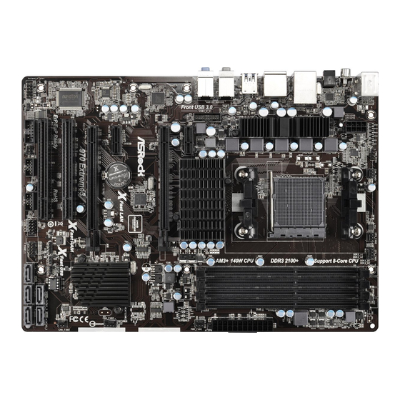
Page 12: Motherboard Layout
T: USB0 B: USB1 Chipset PWR_FAN1 PCIE1 PCIE2 CMOS Fast LAN BATTERY PCIE3 AUDIO CODEC SB950 CHA_FAN1 Chipset PCIE4 970 Extreme3 Super PCI1 Fast USB ErP/EuP Ready RoHS 32Mb CHA_FAN2 SATA3 6Gb/s BIOS CLRCMOS1 SPEAKER1 PLED1 SATA3_3 SATA3_1 PCI2 PANEL 1... -
Page 13: I/O Panel
1.4 I/O Panel PS/2 Mouse Port (Green) Microphone (Pink) LAN RJ-45 Port USB 3.0 Port (USB01) USB 2.0 Ports (USB23) *** 11 eSATA3 Connector Side Speaker (Gray) USB 2.0 Ports (USB01) Rear Speaker (Black) Optical SPDIF Out Port Central / Bass (Orange) Coaxial SPDIF Out Port Line In (Light Blue) PS/2 Keyboard Port (Purple) - Page 14 To enable Multi-Streaming function, you need to connect a front panel audio cable to the front panel audio header. After restarting your computer, you will ind “Mixer” tool on your system. Please select “Mixer ToolBox” , click “Enable playback multi-streaming”, and click “ok”. Choose “2CH”, “4CH”, “6CH”, or “8CH”...
-
Page 15: Installation
2. Installation This is an ATX form factor (12.0-in x 8.6-in, 30.5 cm x 21.8 cm) motherboard. Before you install the motherboard, study the coniguration of your chassis to ensure that the motherboard its into it. Pre-installation Precautions Take note of the following precautions before you install motherboard components or change any motherboard settings. -
Page 16: Cpu Installation
2.1 CPU Installation Step 1. Unlock the socket by lifting the lever up to a 90 angle. Step 2. Position the CPU directly above the socket such that the CPU corner with the golden triangle matches the socket corner with a small triangle. Step 3. -
Page 17: Installation Of Memory Modules (Dimm)
2.3 Installation of Memory Modules (DIMM) This motherboard provides four 240-pin DDR3 (Double Data Rate 3) DIMM slots, and supports Dual Channel Memory Technology. For dual channel coniguration, you always need to install identical (the same brand, speed, size and chip-type) DDR3 DIMM pair in the slots. -
Page 18: Installing A Dimm
Installing a DIMM Please make sure to disconnect power supply before adding or removing DIMMs or the system components. Step 1. Unlock a DIMM slot by pressing the retaining clips outward. Step 2. Align a DIMM on the slot such that the notch on the DIMM matches the break on the slot. -
Page 19: Expansion Slots (Pci And Pci Express Slots)
2.4 Expansion Slots (PCI and PCI Express Slots) There are 2 PCI slots and 4 PCI Express slots on this motherboard. PCI Slots: PCI slots are used to install expansion cards that have the 32-bit PCI interface. PCIE Slots: PCIE1 / PCIE3 (PCIE x1 slot; Black) is used for PCI Express cards with x1 lane width cards, such as Gigabit LAN card and SATA2 card. -
Page 20: Crossfirex Tm
2.5 CrossFireX and Quad CrossFireX Operation Guide This motherboard supports CrossFireX and Quad CrossFireX feature. CrossFireX technology offers the most advantageous means available of combining multiple high performance Graphics Processing Units (GPU) in a single PC. Combining a range of different operating modes with intelligent software design and an innovative interconnect mechanism, CrossFireX enables the highest possible level of performance and image quality in any 3D application. - Page 21 Step 2. Connect two Radeon graphics cards by installing CrossFire Bridge on CrossFire Bridge Interconnects on the top of Radeon graphics cards. (CrossFire Bridge is provided with the graphics card you purchase, not bundled with this motherboard. Please refer to your graphics card vendor for details.) CrossFire Bridge Step 3.
-
Page 22: Driver Installation And Setup
2.5.2 Driver Installation and Setup Step 1. Power on your computer and boot into OS. Step 2. Remove the AMD driver if you have any VGA driver installed in your sys- tem. The Catalyst Uninstaller is an optional download. We recommend using this utility to uninstall any previously installed Catalyst drivers prior to installation. -
Page 23: Surround Display Information
Although you have selected the option “Enable CrossFire ”, the Cross- FireX function may not work actually. Your computer will automatically reboot. After restarting your computer, please conirm whether the option “Enable CrossFire ” in “ATI Catalyst Control Center” is selected or not; if not, please select it again, and then you are able to enjoy the beneit of CrossFireX feature. -
Page 24: Asrock Smart Remote Installation Guide
The Multi-Angle CIR Receiver does not support Hot-Plug function. Please install it before you boot the system. * ASRock Smart Remote is only supported by some of ASRock motherboards. Please refer to ASRock website for the motherboard support list: http://www.asrock.com... -
Page 25: Jumpers Setup
2.8 Jumpers Setup The illustration shows how jumpers are setup. When the jumper cap is placed on pins, the jumper is “Short”. If no jumper cap is placed on pins, the jumper is “Open”. The illustration shows a 3-pin jumper whose pin1 and pin2 are “Short”... -
Page 26: Onboard Headers And Connectors
2.9 Onboard Headers and Connectors Onboard headers and connectors are NOT jumpers. Do NOT place jumper caps over these headers and connectors. Placing jumper caps over the headers and connectors will cause permanent damage of the motherboard! Serial ATA3 Connectors These ive Serial ATA3 (SATA3) connectors support (SATA3_1: see p.12, No. -
Page 27: Front Panel Audio Header
Consumer Infrared Module Header This header can be used to connect the remote (4-pin CIR1) controller receiver. (see p.12 No. 25) Front Panel Audio Header This is an interface for the front PRESENCE# MIC_RET panel audio cable that allows (9-pin HD_AUDIO1) OUT_RET convenient connection and (see p.12 No. - Page 28 PLED (System Power LED): Connect to the power status indicator on the chassis front panel. The LED is on when the system is operating. The LED keeps blinking when the sys-tem is in S1 sleep state. The LED is off when the system is in S3/S4 sleep state or powered off (S5).
- Page 29 CPU Fan Connectors Please connect the CPU fan FAN_SPEED_CONTROL CPU_FAN_SPEED cable to the connector and (4-pin CPU_FAN1) +12V match the black wire to the (see p.12 No. 6) ground pin. 1 2 3 4 Though this motherboard provides 4-Pin CPU fan (Quiet Fan) support, the 3-Pin CPU fan still can work successfully even without the fan speed control function.
- Page 30 HDMI_SPDIF Header HDMI_SPDIF header, providing SPDIF audio output to HDMI (2-pin HDMI_SPDIF1) VGA card, allows the system to see p.12 No. 31) connect HDMI Digital TV/ projector/LCD devices. Please connect the HDMI_SPDIF connector of HDMI VGA card to this header.
-
Page 31: Serial Ata3 (Sata3) Hard Disks Installation
2.10 Serial ATA3 (SATA3) Hard Disks Installation This motherboard adopts AMD SB950 chipset that supports Serial ATA3 (SATA3) hard disks and RAID (RAID 0, RAID 1, RAID 5 and RAID 10) functions. You may install SATA3 hard disks on this motherboard for internal storage devices. This sec- tion will guide you to install the SATA3 hard disks. -
Page 32: Sata3 Hdd Hot Plug Feature And Operation Operation Guide
* The SATA3 Hot Plug feature might not be supported by the chipset because of its limitation, the SATA3 Hot Plug support information of our motherboard is indicated in the product spec on our website: www.asrock.com 2. Make sure your SATA3 HDD can support Hot Plug function from your dealer or HDD user manual. -
Page 33: How To Hot Plug A Sata3 Hdd
How to Hot Plug a SATA3 HDD: Points of attention, before you process the Hot Plug: Please do follow below instruction sequence to process the Hot Plug, improper procedure will cause the SATA3 HDD damage and data loss. Please connect SATA power cable 1x4-pin Step 1 Connect SATA data cable to Step 2... -
Page 34: Driver Installation Guide
STEP 2: Make a SATA3 Driver Diskette. (Please use USB loppy or loppy disk.) A. Insert the ASRock Support CD into your optical drive to boot your system. B. During POST at the beginning of system boot-up, press <F11> key, and then a window for boot devices selection appears. -
Page 35: Installing Windows
STEP 3: Use “RAID Installation Guide” to set RAID coniguration. Before you start to conigure RAID function, you need to check the RAID installation guide in the Support CD for proper coniguration. Please refer to the BIOS RAID installation guide part of the document in the following path in the Support CD: .. -
Page 36: Xp 64-Bit Without Raid Functions
2.15 Installing Windows 7 / 7 64-bit / Vista / Vista 64-bit / XP / ® XP 64-bit Without RAID Functions ® If you want to install Windows 7 / 7 64-bit / Vista / Vista 64-bit / XP / XP 64-bit OS on your SATA3 HDDs without RAID functions, please follow below procedures according to the OS you install. -
Page 37: Installing Windows
2.15.2 Installing Windows 7 / 7 64-bit / Vista / Vista 64-bit ® Without RAID Functions ® If you want to install Windows 7 / 7 64-bit / Vista / Vista 64-bit on your SATA3 HDDs without RAID functions, please follow below steps. Using SATA3 HDDs with NCQ and Hot Plug functions (AHCI mode) STEP 1: Set up UEFI. -
Page 38: Uefi Setup Utility
3. UEFI SETUP UTILITY 3.1 Introduction This section explains how to use the UEFI SETUP UTILITY to conigure your sys- tem. The SPI Memory on the motherboard stores the UEFI SETUP UTILITY. You may run the UEFI SETUP UTILITY when you start up the computer. Please press <F2>... -
Page 39: Navigation Keys
3.1.2 Navigation Keys Please check the following table for the function description of each navigation key. Navigation Key(s) Function Description Moves cursor left or right to select Screens Moves cursor up or down to select items + / - To change option for the selected items <Enter>... -
Page 40: Oc Tweaker Screen
ASRock UCC ASRock UCC (Unlock CPU Core) feature simpliies AMD CPU activation. As long as a simple switch of the UEFI option “ASRock UCC”, you can unlock the extra CPU core to enjoy an instant performance boost. When UCC feature is enabled, the dual-core or triple-core CPU will boost to the... - Page 41 AMD Turbo Core Technology This item appears only when the processor you adopt supports this fea- ture. Use this to select enable or disable AMD Turbo Core Technology. Coniguration options: [Auto] and [Disabled]. The default value is [Auto]. AMD IO C-State Support This allows you to enable or disable AMD IO C-State Support.
- Page 42 Power Down Enable Use this item to enable or disable DDR power down mode. Bank Interleaving Interleaving allows memory accesses to be spread out over banks on the same node, or accross nodes, decreasing access contention. Channel Interleaving It allows you to enable Channel Memory Interleaving. Coniguration op- tions: [Disabled], [Auto].
- Page 43 Four Activate Window (tFAW) Use this item to change Four Activate Window (tFAW) Auto/Manual setting. The default is [Auto]. Voltage Control DRAM Voltage Use this to select DRAM Voltage. The default value is [Auto]. NB Voltage Use this to select NB Voltage. The default value is [Auto]. HT Voltage Use this to select HT Voltage.
-
Page 44: Advanced Screen
3.4 Advanced Screen In this section, you may set the conigurations for the following items: CPU Conigu- ration, Nouth Bridge Coniguration, South Bridge Coniguration, Storage Conigura- tion, Super IO Coniguration, ACPI Coniguration, and USB Coniguration. Setting wrong values in this section may cause the system to malfunction. -
Page 45: Cpu Configuration
3.4.1 CPU Configuration Cool ‘n’ Quiet Use this item to enable or disable AMD’s Cool ‘n’ Quiet technology. The default value is [Enabled]. Coniguration options: [Enabled] and [Disabled]. ® If you install Windows 7 / Vista and want to enable this function, please set this item to [Enabled]. -
Page 46: North Bridge Configuration
3.4.2 North Bridge Configuration Primary Graphics Adapter This item will switch the PCI Bus scanning order while searching for video card. It allows you to select the type of Primary VGA in case of multiple video controllers. The default value of this feature is [PCI Express]. Con- iguration options: [PCI] and [PCI Express]. -
Page 47: South Bridge Configuration
3.4.3 South Bridge Configuration Onboard HD Audio Select [Auto], [Enabled] or [Disabled] for the onboard HD Audio feature. If you select [Auto], the onboard HD Audio will be disabled when PCI Sound Card is plugged. Front Panel Select [Auto] or [Disabled] for the onboard HD Audio Front Panel. On/Off Play Use this item to enable or disable On/Off Play Technology. -
Page 48: Storage Configuration
3.4.4 Storage Configuration SATA Controller Use this item to enable or disable the “SATA Controller” feature. SATA Mode Use this item to adjust SATA Mode. The default value of this option is [IDE Mode]. Coniguration options: [AHCI Mode], [RAID Mode] and [IDE Mode]. If you set this item to RAID mode, it is suggested to install SATA ODD driver on SATA3_5 and eSATA3 ports. -
Page 49: Super Io Configuration
3.4.5 Super IO Configuration Serial Port Use this item to enable or disable the onboard serial port. Serial Port Address Use this item to set the address for the onboard serial port. Coniguration options: [3F8h / IRQ4] and [3E8h / IRQ4]. Infrared Port Use this item to enable or disable the onboard infrared port. -
Page 50: Acpi Configuration
3.4.6 ACPI Configuration Suspend to RAM Use this item to select whether to auto-detect or disable the Suspend-to- RAM feature. Select [Auto] will enable this feature if the OS supports it. Check Ready Bit Use this item to enable or disable the feature Check Ready Bit. Restore on AC/Power Loss This allows you to set the power state after an unexpected AC/power loss. - Page 51 ACPI HPET table Use this item to enable or disable ACPI HPET Table. The default value is [Enabled]. Please set this option to [Enabled] if you plan to use this moth- ® erboard to submit Windows Vista certiication.
-
Page 52: Usb Configuration
3.4.7 USB Configuration USB 2.0 Controller Use this item to enable or disable the use of USB 2.0 controller. USB 3.0 Controller Use this item to enable or disable the use of USB 3.0 controller. Legacy USB Support Use this option to select legacy support for USB devices. There are four coni guration options: [Enabled], [Auto], [Disabled] and [UEFI Setup Only]. -
Page 53: Hardware Health Event Monitoring Screen
3.5 Hardware Health Event Monitoring Screen In this section, it allows you to monitor the status of the hardware on your system, including the parameters of the CPU temperature, motherboard temperature, CPU fan speed, chassis fan speed, and the critical voltage. CPU Fan 1 &... -
Page 54: Boot Screen
3.6 Boot Screen In this section, it will display the available devices on your system for you to conig- ure the boot settings and the boot priority. Setup Prompt Timeout This shows the number of seconds to wait for setup activation key. 65535(0xFFFF) means indeinite waiting. -
Page 55: Security Screen
3.7 Security Screen In this section, you may set or change the supervisor/user password for the system. For the user password, you may also clear it. -
Page 56: Exit Screen
3.8 Exit Screen Save Changes and Exit When you select this option, it will pop-out the following message, “Save coniguration changes and exit setup?” Select [OK] to save the changes and exit the UEFI SETUP UTILITY. Discard Changes and Exit When you select this option, it will pop-out the following message, “Discard changes and exit setup?”... -
Page 57: Software Support
Click on a speciic item then follow the installation wizard to install it. 4.2.4 Contact Information If you need to contact ASRock or want to know more about ASRock, welcome to visit ASRock’s website at http://www.asrock.com; or you may contact your... -
Page 58: Storage Coniguration
Installing OS on a HDD Larger Than 2TB in AHCI Mode ® This motherboard is adopting UEFI BIOS that allows Windows OS to be installed on a large size HDD (>2TB). Please follow below procedure to install the operating system. ®... -
Page 59: Installing Os On A Hdd Larger Than 2Tb In Raid Mode
Installing OS on a HDD Larger Than 2TB in RAID Mode ® This motherboard is adopting UEFI BIOS that allows Windows OS to be installed on a large size HDD (>2TB). Please follow below procedure to install the operating system. ®... - Page 60 7. And then key in drvcfg –s [Drv number] [Ctrl number] to enter Raid Utility. For example: key in drvcfg –s 4E B5. 8. Choose Logical Drive Main Menu to set up Raid Drive. 9. Choose Logical Drive Create Menu to create a Raid Drive. 10.
- Page 61 11. Press Space on keyboard to toggle checkbox. 12. Choose Ld Size setting, and key in the Raid size. 13. After set up Raid size, please click Start to Create. 14. Press <F10> to exit Utility. 15. During reboot, please press <F11> to enter Boot Manual. Choose UEFI: SCSI CD/DVD Drive.
- Page 62 ® 16. Follow Windows Installation Guide to install OS. ® If you install Windows 7 64-bit / Vista 64-bit in a large hard disk (ex. Disk ® volume > 2TB), it may take more time to boot into Windows or install driver/ utilities.
- Page 63 B. Disable “Volume Shadow Copy” service. a. Type “computer management” in the Start Menu, then press “Enter”. b. Go to “Services and Applications>Services”; Then double click “Volume Shadow Copy”. c. Set “Startup type” to “Disable” then Click “OK”.
- Page 64 C. Reboot your system. D. After reboot, please start to install motherboard drivers and utilities. ® Windows 7 64-bit: A. Please request the hotix KB2505454 thru this link: http://support.microsoft.com/kb/2505454/ ® B. After installing Windows 7 64-bit, install the hotix kb2505454. (This may take long time;...
Need help?
Do you have a question about the 970 Extreme3 and is the answer not in the manual?
Questions and answers