
Subscribe to Our Youtube Channel
Related Manuals for Acer Aspire 1300


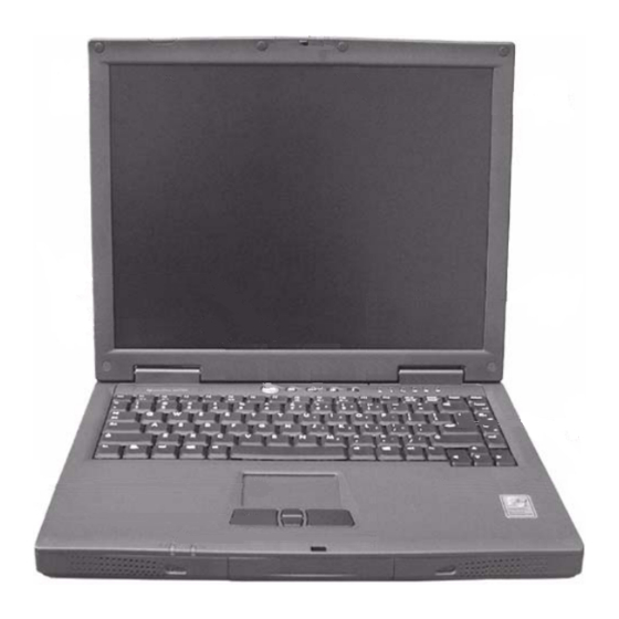
Summary of Contents for Acer Aspire 1300
- Page 1 Acer Aspire 1300 Series Service Guide Service guide files and updates are available on the ACER/CSD web; for more information, please refer to http://csd.acer.com.tw PART NO.: VD.A0307.001 PRINTED IN TAIWAN...
-
Page 2: Revision History
Revision History Please refer to the table below for the updates made on Aspire 1300 service guide. Date Chapter Updates... - Page 3 Copyright Copyright © 2002 by Acer Incorporated. All rights reserved. No part of this publication may be reproduced, transmitted, transcribed, stored in a retrieval system, or translated into any language or computer language, in any form or by any means, electronic, mechanical, magnetic, optical, chemical, manual or otherwise, without the prior written permission of Acer Incorporated.
- Page 4 Conventions The following conventions are used in this manual: Denotes actual messages that appear SCREEN MESSAGES on screen. NOTE Gives bits and pieces of additional information related to the current topic. WARNING Alerts you to any damage that might result from doing or not doing specific actions.
- Page 5 DIFFERENT part number code to those given in the FRU list of this printed Service Guide. You MUST use the list provided by your regional Acer office to order FRU parts for repair and service of customer machines.
-
Page 7: Table Of Contents
Table of Contents Chapter 1 System Specifications Features ............9 System Block Diagram . - Page 8 Aspire 1300 ........
-
Page 9: System Specifications
The thin-film transistor (TFT) liquid crystal display (LCD) supports extended graphics array (XGA) resolution, enabling 16.7 million colors at 1024X768 Aspire 1300 series notebook computer features an accelerated graphics port (AGP) video system integrated in the VIA S3 Savage 4 KN 133 (Twister K) chipset. This provides a robust solution and enables high quality video output. - Page 10 Human-centric design and ergonomics All-in-one design (incorporating hard drive, optical drive and floppy disk drive) Rugged, yet extremely protable, construction Stylish appearance Full-size keyboard with 4 programmable launch keys Comfortable palm rest area with well-positioned touchpad Expansion Upgradeable memory modules and hard disk PC card slot enables a range of add-on options Keyboard and Pointing Device 87-(US)/88(Europe)-key Windows keyboard...
-
Page 11: System Block Diagram
System Block Diagram SYSTEM BLOCK DIAGRAM PCI ..CLOCK CK-GEN Processor ( Socket A ) DC/DC ICS9248-168-TSSOP P3,4 Max1632,Max1717 19V IN P23,P24 5V,3V,CPUCORE VCC etc. Host Bus POWER IN Battery Charger INTA#(VGA) SO- DIMM THERMAL Twister-K SENSOR NB VT8362 THERMAL DIODE IN SAVAGE4 SO- DIMM LCD/INV... -
Page 12: Board Layout
Board Layout Top View A E T 2 A M B 6 2 R E V : A E T 2 A M B 6 2 R E V : A E T 2 A M B 6 2 R E V : A E T 2 A M B 6 2 R E V : A E T 2 A M B 6 2 R E V : A E T 2 A M B 6 2 R E V :... - Page 13 North Bridge VT8362 Headphone Jack RTC Battery Socket Microphone-in Jack Keyboard FFC connector LAN Connector CD/DVD-ROM Module Connector Modem Connector Chapter 1...
-
Page 14: Bottom View
Bottom View D E T 2 M B 6 D 2 R E V : D D E T 2 M B 6 D 2 R E V : D D E T 2 M B 6 D 2 R E V : D D E T 2 M B 6 D 2 R E V : D D E T 2 M B 6 D 2 R E V : D D E T 2 M B 6 D 2 R E V : D... -
Page 15: Outlook View
Outlook View A general introduction of ports allow you to connect peripheral devices, as you would with a desktop PC. Front View Item Description Display Large liquid crystal display (LCD) provides visual output. Launch keys 4 buttons that can be programmed to start frequently used applications. - Page 16 Palm rest Provides a comfortable platform for your hands when typing on the keyboard. Keyboard Full-size keyboard for inputting typed data. Status indicators Light emitting diodes (LED) that show the status of the computer and its componenets. Latch Locks and releases the lid. Chapter 1...
-
Page 17: Left Panel
Left Panel Item Description Modem jack Connects the built-in fax/data modem to a phone line. Network jack Connects the computer to an Ethernet 10/ 100-based network. Microphone-in jack Connects an external microphone for audio input. Headphone jack Connects headphones for audio output. PC card eject button Press the eject button to remove a PC card for the PC card slot. -
Page 18: Right Panel
Right Panel Item Description Optical drive Depending on your model, the optical drive is one of the following: CD-ROM drive for reading CDs. DVD-ROM drive for reading CDs and DVDs. DVD/CD-RW combo drive for reading CDs and DVDs, and writing to CD-Rs and CD- RWs. -
Page 19: Rear Panel
Rear Panel Item Description Kensington lock slot For attaching a security connector. DC-in jack Connects the AC adapter. USB ports 2 ports for connecting USB devices. External display port Connects an external (VGA) display monitor. Parallel port Connects a parallel device, such as a printer. -
Page 20: Bottom Panel
Bottom Panel Item Description Ventilation slots Enables the computer to stay cool, even after prolonged use. Battery The computer’s removable battery. Battery release latch Slide and hold the latch, and then pull the battery to remove it from the unit. Hard disk bay Removable cover provides access to the computer’s hard drive. -
Page 21: Indicators
Indicators Your computer provides an array of six indicators located above the keyboard, in addition to two indicators positioned at the from of the palm rest area. These indicators show the status of the computer and its components. The six indicators located above the keyboard provide the following status information:. Description Caps Lock active Num Lock active (Note: the keypad lock... -
Page 22: Keyboard
Keyboard Special keys Lock keys The keyboard features full-size keys with an embedded keypad, separate cursor control keys, two Windows keys, and twelve function keys (hot keys). NumLK Scr LK Caps Lock Lock Key Description Caps Lock When Caps Lock is on, all alphabetic characters are typed in uppercase. Toggle on and off by pressing the Caps Lock key on the left side of the keyboard. - Page 23 Desired Access Num Lock On Num Lock On Number keys on embedded Type numbers using keypad embedded keypad in the normal way. Hold down the jkey while Cursor-control keys on Hold Fn key while using embedded keypad using the cursor keys on the cursor-control keys.
- Page 24 Hot Key Function Fn + l Decreases the display panel brightness. Fn + m Increases the display panel brightness. Fn + p Toggles the display setting between (1) the computer’s LCD panel, (2) an external display device connected to the external display port, and (3) simultaneous display on the computer’s LCD panle and an external display device.
-
Page 25: Touchpad
Touchpad The built-in touchpad is a PS/2-compatible pointing device that senses movement on its surface. This cursor responds to your finger movements on the touchpad. In addition, the two click buttons provide the same functionality as a computer mouse, while the scroll key enables easy up and down scrolling in documents and web pages. - Page 26 NOTE: Keep your fingers, as well as the surface of the touchpad dry and clean. The touchpad is sensitive to your finger movements: the lighter the touch, the better the response. Tapping hard will not increase the touchpad’s responsiveness. Chapter 1...
-
Page 27: Launch Keys
1, key 2, key 3 and key 4. By default, key 1 is used to launch the email application and key 2 is used to launch the Internet browser. Keys 3 and 4 start the Launch Manager application. All four launch keys can be set by the user. To see the launch keys, run the Acer Launch Manger. Description Email Launches your email application. -
Page 28: Hardware Specifications And Configurations
AMD Athlon XP 1400+ (1.2G) / 1600+ (1.4G) / 1800+ (1.5G) 35W CPU package OPGA CPU core voltage 1.2V/1.45V BIOS Item Specification BIOS vendor Acer BIOS Version BIOS ROM type Flash ROM BIOS ROM size 512KB BIOS package TSOP Supported protocols ACPI 1.0b,APM 1.2, PC Card 95, SM BIOS 2.3, EPP/IEEE 1284, ECP/... - Page 29 Memory Combinations Slot 1 Slot 2 Total Memory 64MB 64 MB 64MB 64 MB 128MB 128 MB 64MB 64MB 128 MB 128MB 128 MB 64MB 128MB 192MB 128MB 64MB 192MB 128MB 128MB 256MB 256MB 64MB 320MB 64MB 256MB 320MB 256MB 128MB 384MB 128MB...
- Page 30 Floppy Disk Drive Interface Item Specification Power Requirement Input Voltage (V) +5V +/- 10% Hard Disk Drive Interface Item Specification Vendor & Model Name TOSHIBA 20G(MK2018GAP), TITAN 20G(IC25N020ATCS04-0), 07N8325, CASCADE Capacity (MB) 20000 20000 Bytes per sector Data heads Drive Format Disks Spindle speed (RPM) 4200 RPM...
- Page 31 Audio Interface Item Specification Audio Controller Conexant CX 20468-21 Audio onboard or optional Built-in Mono or Stereo Stereo Resolution 20 bit stereo Digital to analog converter 18 bit stereo Analog to Ditial converter Compatibility Microsoft PC98/PC99, AC97 2.1 Mixed sound source Line-in, CD, Video, AUX Voice channel 8/16-bit, mono/stereo...
- Page 32 USB Port Item Specification USB Compliancy Level OHCI USB 1.1 Number of USB port Location Right panel Serial port function control Enable/Disable by BIOS Setup PCMCIA Port Item Specification PCMCIA controller OZ 6912 Supports card type Type-III/II Number of slots One type-III Access location Left side...
- Page 33 Battery Item Specification Package voltage Li-ion 14.8V/ Ni-MH 9.6V DC -AC LCD inverter Item Specification Vendor & model Quanta 3HYA1 IV0008 name Input voltage (V) 8(min.) 20(max.) Input current (mA) 520(max.) Output voltage 660(typ.) (Vrms, no load) Output voltage 52(min.) 58(typ.) 64(max.) frequency (kHz)
- Page 34 AC Adapter Item Specification Input Requirements Maximum input current (A, 2.25A @ 90Vac @90Vac, full load) 1.125A @ 180Vac Nominal frequency (Hz) 47 - 63 Frequency variation range (Hz) 47 - 63 Nominal voltages (Vrms) 100- 240 Inrush current The maximum inrush current will be less than 50A and 100A when the adapter is connected to 115Vac(60Hz) and 230Vac(50Hz) respectively.
- Page 35 Power Management Power Saving Mode Phenomenon Display Standby Mode The display shuts off Keyboard, built-in touchpad, and an external PS/2 pointing device are idle for a specified period. Hard Disk Standby Mode Hard disk drive is in standby mode. (spindle turned-off) Hard disk is idle within a specified period of time Environmental Requirements Item...
- Page 36 I/O Address Map I/O Address Function 040-043 Timer 1 060, 064 Keyboard controller 87570 chip select System speaker 040B DMA controller-1 System speaker 070-073 Real-time clock and NMI mask 080-08F DMA page register 0A0-0A1 Interrupt controller-2 0C0-0DF DMA controller-2 0F0-0FF Numeric data processor 66, 62 Power management controller...
-
Page 37: System Utilities
Chapter 2 System Utilities BIOS Setup Utility The BIOS Setup Utility is a hardware configuration program built into your computer’s BIOS (Basic Input/ Output System). Your computer is already properly configured and optimized, and you do not need to run this utility. However, if you encounter configuration problems, you may need to run Setup. -
Page 38: Startup
Startup The Startup screen displays a summary of your computer hardware information, and also includes basic setup parameters. After you enter BIOS, you will first see the system information on the first page, then you can useuse the cursor up/down keys ( wy) to select the parameter you like to change. NOTE: The screen above is for reference only. -
Page 39: Exit
Exit The Exit screen contains parameters that help safeguard and protect your computer from unauthorized use. The table below describes the parameters in this screen. Parameter Description Save and Reboot Saves changes made and reboot the system. Exit (No Save) Discards changes made and exits the BIOS Setup Utility. -
Page 40: Bios Flash Utility
Acer Headquarters. You can utilize it as a basic diagnostic tool. To get this program, find it in the Aspire 1300- service CD kit. To better fit local service requirements, your regional office MAY have other diagnostic program. Please contact your regional offices or the responsible personnel/channel to provide you with further technical details. -
Page 41: Machine Disassembly And Replacement
Chapter 3 Machine Disassembly and Replacement This chapter contains step-by-step procedures on how to disassemble the notebook computer for maintenance and troubleshooting. To disassemble the computer, you need the following tools: Wrist grounding strap and conductive mat for preventing electrostatic discharge small Philips screwdriver flat head screwdriver Philiips screwdriver... -
Page 42: General Information
General Information Before You Begin Before proceeding with the disassembly procedure, make sure that you do the following: Turn off the power to the system and all peripherals. Unplug the AC adapter and all power and signal cables from the system. Remove the battery pack. -
Page 43: Disassembly Procedure Flowchart
Disassembly Procedure Flowchart The flowchart on the succeeding page gives you a graphic representation on the entire disassembly sequence and instructs you on the components that need to be removed during servicing. For example, if you want to remove the system board, you must first remove the keyboard, then disassemble the inside assembly frame in that order. - Page 44 15.0" LCD Module LCD Bezel Inverter Board LCD Hinges LCD Panel LCD Brackets LCD Cable Screw List Item Description Screw MBEA1001012 (Screw Nut-I/O) Screw MM25050IL64 (MM2.5X5.0) Screw MM25060PCI5 (MM2.5X6.0-P) Screw MM20040ICI8 (MM2.0X4.0NYLOK) Screw MM25040I243 (MM2.5 X4.0) Screw MM20025ICI6 (MM2.0X2.5) Screw MM25030ICI7 (MM2.5X3.0) Screw MM30035I354 (MM3.0X3.5) Screw MM20030ICI3 (MM2.0X3.0) Screw MS20040IEJ3 (MS2.0X4.0)
-
Page 45: Removing The Battery Pack
Removing the Battery Pack Slide the battery latch. Then remove the battery pack. Chapter 3... -
Page 46: Removing The Memory/Hdd Module
Removing the Memory/HDD Module Remove the screws that secure the ram door. Remove the ram door. Prize the memory lock with fingers then remove the memory. Unscrew the two screws that secure the HDD module. Then remove the HDD module from the notebook computer. Chapter 3... -
Page 47: Removing The Keyboard/Lcd Module
Removing the Keyboard/LCD Module Use a flat head screwdriver to prize the middle cover. Please be careful. Do not scrape the middle cover. Remove the middle cover. Unscrew the three screws that secure the keyboard. Next, turn over the keyboard. Disconnect the keyboard connector then remove the keyboard. -
Page 48: Disassembling The Main Unit
Disassembling the Main Unit Disconnect the fan connector. Remove the three screws holding the fan then remove the fan from the main unit. Unscrew the five screws that secure the thermal module then remove the thermal module. Use a tool to take out CPU from CPU socket. Unscrew the screw holding the optical drive. - Page 49 11. Press the cover latch locating on the right upper corner of the upper case. 12. Then detach the upper case from the lower assembly. 13. Unscrew the four screws that secure the FDD module. 14. Disconnect the FDD FFC then remove the FDD module from the main unit. 15.
- Page 50 22. Unscrew the four screws that lock the special nuts on the main board. Chapter 3...
-
Page 51: Disassembling The Lcd Module-14.1 Inch
Disassembling the LCD Module-14.1 Inch First, remove the six screw pads then remove the six screws as shown here. Detach the LCD bezel carefully. Disconnect the inverter power cable and LCD CCFT cable, then remove the inverter board. Unscrew the four screws that fix the left and right hinges. Remove the right and the left hinges. -
Page 52: Disassembling The Lcd Module-15.1 Inch
Disassembling the LCD Module-15.1 Inch First, remove the two screw pads then remove the two screws as shown here. Detach the LCD bezel carefully. Detach the four square screw pads. Two on each side. Unscrew the six screws that fix LCD to the LCD panel; three on each side. Remove the four screws that fix the left and the right hinges;... -
Page 53: Disassembling The External Modules
Disassembling the External Modules Disassembling the HDD Module Remove the four screws on HDD tray, two on each side. Take the HDD off the HDD tray. Disassembling the Floppy Disk Drive Module Remove the two screws holding the FDD holder. Remove the screw that fixs the FDD holder then remove the FDD from the FDD holder. - Page 54 Chapter 3...
-
Page 55: Troubleshooting
Troubleshooting Use the following procedure as a guide for computer problems. NOTE: The diagnostic tests are intended to test this model. Non-Acer products, prototype cards, or modified options can give false errors and invalid system responses. Duplicate symptom and obtain the failing symptoms in as much detail as possible. -
Page 56: System Check Procedures
System Check Procedures External Diskette Drive Check Do the following to isolate the problem to a controller, driver, or diskette. A write-enabled, diagnostic diskette is required. NOTE: Make sure that the diskette does not have more than one label attached to it. Multiple labels can cause damage to the drive or cause the drive to fail. -
Page 57: Keyboard Or Auxiliary Input Device Check
Keyboard or Auxiliary Input Device Check Remove the external keyboard if the internal keyboard is to be tested. If the internal keyboard does not work or an unexpected character appears, make sure that the flexible cable extending from the keyboard is correctly seated in the connector on the system board. If the keyboard cable connection is correct, run the Keyboard Test. -
Page 58: Touchpad Check
Check the Battery Pack To check the battery pack, do the following: From Software: Check out the Power Management in control Panel In Power Meter, confirm that if the parameters shown in the screen for Current Power Source and Total Battery Power Remaining are correct. -
Page 59: Power-On Self-Test (Post) Error Message
Power-On Self-Test (POST) Error Message The POST error message index lists the error message and their possible causes. The most likely cause is listed first. NOTE: Perform the FRU replacement or actions in the sequence shown in FRU/Action column, if the FRU replacement does not solve the problem, put the original part back in the computer. -
Page 60: Index Of Error Messages
Index of Error Messages Error Message List Error Messages FRU/Action in Sequence Struck Key See ““Keyboard or Auxiliary Input Device Check” on page 57 System CMOS checksum bad - Default RTC battery configuration used Run BIOS Setup Utility to reconfigure system, then reboot system. Real time clock error RTC battery Run BIOS Setup Utility to reconfigure system time, then reboot... - Page 61 Error Message List No beep Error Messages FRU/Action in Sequence Power-on indicator turns off and LCD is blank. Power source (battery pack and power adapter.) See “Power System Check” on page 57 Ensure every connector is connected tightly and correctly. Reconnect the DIMM.
-
Page 62: Index Of Symptom-To-Fru Error Message
Index of Symptom-to-FRU Error Message LCD-Related Symptoms Symptom / Error Action in Sequence LCD backlight doesn't work First, plug a monitor to CRT port. Next, enter BIOS utility to running “Load Default Settings” then reboot the system. Reconnect the LCD connectors. Keyboard (if the brightness function key doesn't work). - Page 63 Power-Related Symptoms Symptom / Error Action in Sequence Battery can’t be charged or discharged See “Check the Battery Pack” on page 58. Battery pack Main board System hang during POST ODD/HDD/FDD/RAM module Main board PCMCIA-Related Symptoms Symptom / Error Action in Sequence System cannot detect the PC Card (PCMCIA) PCMCIA slot assembly Main board...
- Page 64 Power Management-Related Symptoms Symptom / Error Action in Sequence The system doesn't resume from hibernation/ Connect AC adapter then check if the system resumes from standby mode. Standby/Hibernation mode. Check if the battery is low. Hard disk drive Main board The system doesn't resume from standby mode LCD cover switch after opening the lid of the portable computer.
- Page 65 Modem/LAN-Related Symptoms Symptom / Error Action in Sequence Internal modem does not work correctly. See “System Diagnostic Diskette” on page 40. Phone cable Driver Reconnect the Internal modem cable to the main board tightly. Main board Internal LAN does not work correctly Lan cable Driver Main board...
-
Page 66: Intermittent Problems
Intermittent Problems Intermittent system hang problems can be caused by a variety of reasons that have nothing to do with a hardware defect, such as: cosmic radiation, electrostatic discharge, or software errors. FRU replacement should be considered only when a recurring problem exists. When analyzing an intermittent problem, do the following: Run the diagnostic test for the system board in loop mode at least 10 times. -
Page 67: Undetermined Problems
System Check” on page 57): Power-off the computer. Visually check them for damage. If any problems are found, replace the FRU. Remove or disconnect all of the following devices: Non-Acer devices Printer, mouse, and other external devices Battery pack Hard disk drive... - Page 68 Chapter 4...
-
Page 69: Jumper And Connector Locations
Chapter 5 Jumper and Connector Locations Top View CON2 CON3 PSW1 CON1 SW1 CN25 RJ11 RJ45 DAET2AMB6D2 REV:D DAET2AMB6D2 REV:D DAET2AMB6D2 REV:D DAET2AMB6D2 REV:D DAET2AMB6D2 REV:D DAET2AMB6D2 REV:D DAET2AMB6D2 REV:D DAET2AMB6D2 REV:D DAET2AMB6D2 REV:D CON5 CON7 CON8 CON9 JSPKL1 CON11 JSPKR1 CON2 Parallel connector... -
Page 70: Bottom View
Bottom View PSW2 DAET2AMB6D2 REV:D DAET2AMB6D2 REV:D DAET2AMB6D2 REV:D DAET2AMB6D2 REV:D DAET2AMB6D2 REV:D DAET2AMB6D2 REV:D DAET2AMB6D2 REV:D DAET2AMB6D2 REV:D DAET2AMB6D2 REV:D CN10 AMC20463-002 AMC20463-002 AMC20463-002 AMC20463-002 AMC20463-002 AMC20463-002 Modem cable connector Debug port connector Modem cable connector CN10 DIMM connector 2 DIMM connector 1 PSW2 System-off switch... -
Page 71: Fru (Field Replaceable Unit) List
RMA (Return Merchandise Authorization). Please also note that there are some common parts for Aspire 1300, yet the LCD modules are different in two model. Please note that WHEN ORDERING FRU PARTS, you should check the most up-to-date information available on your regional web or channel. -
Page 72: Exploded Diagram
Exploded Diagram THE SYSTEM LCD 14.1” Chapter 6... - Page 73 LCD 15.0” FDD ASSY Chapter 6...
- Page 74 Picture Partname And Description Part Number CPU/Processor AMD ATHLON XP 1.2G(1400+) 35W TOROUGHBRED KC.A1402.001 SYSTEM AMD ATHLON XP 1.4G(1600+) 35W TOROUGHBRED AMD ATHLON XP 1.5G(1800+) 35W TOROUGHBRED KC.A1802.001 Memory MEMORY SDIMM 128M MICRON PC-133 KS.12804.001 MEMORY SDIMM 128M INFINION PC-133 KS.12802.002 MEMORY SDIMM 128M NANYA PC-133 KS.12803.001...
- Page 75 Picture Partname And Description Part Number 9-LCD 15.0” ASSY 14.1” HINGE R/L 6K.A03V7.004 3-LCD 15.0” ASSY 15.0” BRACKET R 33.A03V7.006 4--LCD 15.0” ASSY 15.0” BRACKET L 33.A03V7.007 1-LCD 15.0” LCD PANEL WITH LOGO 14.1” 60.A03V7.003 LCD PANEL WITH LOGO 15.0” 60.A03V7.005 14-LCD LCD BEZEL 14.1”...
- Page 76 Picture Partname And Description Part Number 3-FDD ASSY FDD HOLDER-PANASONIC 33.A03V7.002 HDD/ Hard Disk Drive HDD MODULE 20G TOSHIBA 6M.A03V7.021 HDD MODULE 20G IBM 6M.A03V7.022 HDD MODULE 30G IBM 6M.A03V7.023 HDD TOSHIBA 20G(MK2018GAP), TITAN KH.25204.001 HDD IBM 20G(IC25N020ATCS04-0), 07N8325, KH.25202.001 CASCADE KH.25302.001 HDD IBM 30G(IC25N030ATCS04-0), 07N8326,...
- Page 77 Picture Partname And Description Part Number ODD BRACKET 33.A03v7.001 31.A03V7.001 SYSTEM Cables POWER CORD-US 27.A03V7.001 POWER CORD-CONTINENTAL 27.A03V7.002 POWER CORD-PRC 27.A03V7.003 POWER CORD-UK 27.A03V7.004 POWER CORD-ITALIAN 27.A03V7.005 POWER CORD-DANISH 27.A03V7.006 POWER CORD-SWISS 27.A03V7.007 Boards MAIN BOARD W/LAN MB.A0306.001 SYSTEM Adapter ADAPTER DELTA 75W ADP-75FB B (W PFC), 3P AP.A0305.001 ADAPTER LITE-ON 75W PA-1750-02Q(W PFC), 3P...
- Page 78 Picture Partname And Description Part Number 9-THE ASPIRE 1300 KEYBOARD JIMMOLD US KB.A0305.001 SYSTEM ASPIRE 1300 KEYBOARD JIMMOLD UK KB.A0305.002 ASPIRE 1300 KEYBOARD JIMMOLD GERMAN KB.A0305.003 ASPIRE 1300 KEYBOARD JIMMOLD ITALIAN KB.A0305.004 ASPIRE 1300 KEYBOARD JIMMOLD CHINESE KB.A0305.005 ASPIRE 1300 KEYBOARD JIMMOLD FRENCH KB.A0305.006...
- Page 79 Picture Partname And Description Part Number 15/16-LCD HINGE COVER KIT-14.1” 6K.A03V7.001 15.0” 15/16-LCD HINGE COVER KIT-15.0” 6K.A03V7.002 15.0” TOP COVER SHIELDING 34.A03V7.001 SYSTEM Others SPEAKER ASSY (L & R) 6K.A03V7.006 THERMAL MODULE W/ HEATSINK 6K.A03V7.007 SYSTEM THERMAL PAD 47.A03V7.001 RUBBER FEET (BASE) 47.A03V7.002 12-LCD LCD DOWNSIDE TAPE...
- Page 80 Picture Partname And Description Part Number SCREW, MM25060PCI5 86.A03V7.003 SCREW, MM20040ICI8 86.A03V7.004 SCREW, MM25040I243 86.A03V7.005 SCREW MM20025ICI6 86.A03V7.006 SCREW MS17025B202 86.A03V7.007 SCREW MM17035IEC8 86.A03V7.008 SCREW MM25030ICI7 86.A03V7.009 SCREW MM30035I354 86.A03V7.010 SCREW MM20030ICI3 86.A03V7.011 SCREW MM20060ICI7 86.A03V7.012 SCREW MS20025IG57 86.A03V7.013 SCREW MS25040IH41 86.A03V7.014 SCREW MM20040IBJ7 86.A03V7.015...
- Page 81 Chapter 6...
-
Page 82: Aspire 1300
Appendix A Model Definition and Configuration Aspire 1300 series Model Memo Bat. Number (GB) 1300X AMD Athlon 14.1XGA 24X CD-ROM XP1400+ 1300XC AMD Athlon 14.1XGA 8/16/12/24 Li-ion XP1400+ Combo 1300XV AMD Athlon 14.1XGA 8X DVD Li-ion XP1400+ 1300DXV AMD Duron 1.2GHz 14.1XGA... -
Page 83: Main Features
Main Features AMD Athlon XP1400+, XP1600+, or higher processor VIA ProSavage KN133 (Twister K)+VT8362 & VT8231 chipset 2 memory slots supporting 133MHz SDRAM (PC-133), upgradeable to 1GB 10GB, 20GB or 30GB Enhanced-IDE hard disk Microsoft Windows XP operating system Appendix A... - Page 84 Appendix A...
-
Page 85: Appendix B Test Compatible Components
Appendix B Test Compatible Components This computer’s compatibility is tested and verified by Acer’s internal testing department. All of its system functions are tested under Windows XP Home environment. Refer to the following lists for components, adapter cards, and peripherals which have passed these tests. -
Page 86: Microsoft Windows Xp (Home) Environment Test
Microsoft Internet Keyboard Pro Gateway Keyboard SK-9910U Gateway Keyboard SK-9926 I/O - USB (Mouse) Microsoft Optical USB Mouse Lotitech Wheel Mouse Acer USB Mouse M012B0 I/O-USB (Camera) Microtek EyeStar U2S PC Camera USC-1 I/O-USB (HDD) Argosy HDD I/O-USB (CD-ROM) IOMega ZIP CD650... - Page 87 Item Specifications Audio Jacks JS-100 Jazz 3D Speaker SONY Earphone MDR-CD60 Microsoft Microphone Microphone Conderser MIC. Dynamic MIC. Appendix B...
- Page 88 Appendix B...
-
Page 89: Appendix C Online Support Information
This section describes online technical support services available to help you repair your Acer Systems. If you are a distributor, dealer, ASP or TPM, please refer your technical queries to your local Acer branch office. Acer Branch Offices and Regional Business Units may access our website. However some information sources will require a user i.d. - Page 90 Appendix C...
-
Page 91: Index
Index Battery Pack 44 CD-ROM/DVD-ROM Module 48 Floppy Disk Drive 51, 52 AC Adapter 33 Machine 41 ACPI 1.0a 28 Procedure Flowchart 43 AFLASH Utility 40 Display 11 Audio 31, 32 DVD-ROM Interface 30 Battery 32 Error Symptom-to-Spare Part Index 59 Battery Pack 45 External CD-ROM Drive Check 56 BIOS 28... - Page 92 Memory Check 57 USB 32 Model Definition 82 Utility BIOS 37 Modem 29 Modem Combo Card external 47 Video 31 Resolutions 31 Video controller 32 Online Support Information 89 Overview 82 Windows XP Home Environment Test Panel 15 Bottom 20 left 15 Rear 18 right 18...
Need help?
Do you have a question about the Aspire 1300 and is the answer not in the manual?
Questions and answers