ASROCK 960GM-S3 FX User Manual
User manual
Hide thumbs
Also See for 960GM-S3 FX:
- Installation manual (17 pages) ,
- Quick installation manual (159 pages)

Subscribe to Our Youtube Channel
Related Manuals for ASROCK 960GM-S3 FX


Summary of Contents for ASROCK 960GM-S3 FX
-
Page 1: User Manual
960GM-GS3 FX / 960GM-S3 FX User Manual Version 1.0 Published September 2011 Copyright©2011 ASRock INC. All rights reserved. 1 1 1 1 1... - Page 2 (including damages for loss of profits, loss of business, loss of data, interruption of business and the like), even if ASRock has been advised of the possibility of such damages arising from any defect or error in the manual or product.
-
Page 3: Table Of Contents
............Package Contents ..............5 Specifications ................6 Motherboard Layout (960GM-GS3 FX / 960GM-S3 FX) ..... 11 I/O Panel (960GM-GS3 FX) ............12 I/O Panel (960GM-S3 FX) ............13 2 . 2 . 2 . 2 . 2 . Installation... - Page 4 3 . 3 . 3 . 3 . 3 . BIOS S BIOS S BIOS S BIOS SETUP UTILITY ETUP UTILITY ETUP UTILITY ETUP UTILITY ..........................................34 BIOS S ETUP UTILITY ........... Introduction ................34 3.1.1 BIOS Menu Bar ............... 34 3.1.2 Navigation Keys .............
-
Page 5: Introduction Introduction
Introduction Introduction Introduction Thank you for purchasing ASRock 960GM-GS3 FX / 960GM-S3 FX motherboard, a reliable motherboard produced under ASRock’s consistently stringent quality control. It delivers excellent performance with robust design conforming to ASRock’s com- mitment to quality and endurance. -
Page 6: Specifications
- 5.1 CH HD Audio (Realtek ALC662 Audio Codec) Audio - Supports THX TruStudio - 960GM-GS3 FX Realtek PCIE x1 Gigabit LAN RTL8111E, speed 10/100/1000 Mb/s - 960GM-S3 FX Realtek PCIEx1 LAN 8105EL, speed 10/100 Mb/s - Supports Wake-On-LAN - Supports PXE 6 6 6 6 6... - Page 7 - Drivers, Utilities, AntiVirus Software (Trial Version), Support CD AMD OverDrive Utility, CyberLink MediaEspresso 6.5 Trial, ASRock Software Suite (CyberLink DVD Suite - OEM and Trial; ASRock MAGIX Multimedia Suite - OEM) - ASRock OC Tuner (see CAUTION 7) Unique Feature...
- Page 8 Certifications - ErP/EuP Ready (ErP/EuP ready power supply is required) (see CAUTION 17) * For detailed product information, please visit our website: http://www.asrock.com WARNING Please realize that there is a certain risk involved with overclocking, including adjusting the setting in the BIOS, applying Untied Overclocking Technology, or using the third- party overclocking tools.
- Page 9 - ASRock APP Charger. Simply installing the APP Charger driver, it makes your iPhone charged much quickly from your computer and up to 40% faster than before. ASRock APP Charger allows you to quickly charge many Apple devices simultaneously and even supports continuous charging when your PC enters into Standby mode (S1), Suspend to RAM (S3), hibernation mode (S4) or power off (S5).
- Page 10 IE8. ASRock website: http://www.asrock.com/Feature/SmartView/index.asp 13. ASRock XFast USB can boost USB storage device performance. The performance may depend on the property of the device. 14. ASRock XFast LAN provides a faster internet access, which includes below benefits.
-
Page 11: Motherboard Layout (960Gm-Gs3 Fx / 960Gm-S3 Fx)
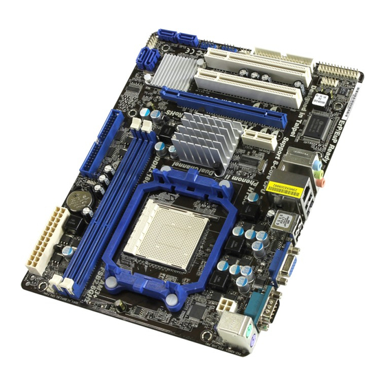
1.3 Motherboard L 1.3 Motherboard L 1.3 Motherboard Layout (960GM- ayout (960GM- ayout (960GM- ayout (960GM- GS3 FX / 960GM-S3 FX) GS3 FX / 960GM-S3 FX) GS3 FX / 960GM-S3 FX) GS3 FX / 960GM-S3 FX) 1.3 Motherboard L 1.3 Motherboard L... -
Page 12: I/O Panel (960Gm-Gs3 Fx)
1.4 I/O P 1.4 I/O Panel (960GM- 1.4 I/O P anel (960GM- anel (960GM- anel (960GM- GS3 FX) GS3 FX) GS3 FX) GS3 FX) 1.4 I/O P 1.4 I/O P anel (960GM- GS3 FX) PS/2 Mouse Port (Green) Microphone (Pink) USB 2.0 Ports (USB23) USB 2.0 Ports (USB01) RJ-45 Port... -
Page 13: I/O Panel (960Gm-S3 Fx)
1.5 I/O P 1.5 I/O Panel (960GM-S3 FX) 1.5 I/O P anel (960GM-S3 FX) anel (960GM-S3 FX) anel (960GM-S3 FX) 1.5 I/O P 1.5 I/O P anel (960GM-S3 FX) PS/2 Mouse Port (Green) Microphone (Pink) USB 2.0 Ports (USB23) USB 2.0 Ports (USB01) -
Page 14: Installation
2. 2. 2. 2. 2. Installation Installation Installation Installation Installation This is a Micro ATX form factor (9.6-in x 7.2-in, 24.4 cm x 18.3 cm) motherboard. Before you install the motherboard, study the configuration of your chassis to en- sure that the motherboard fits into it. Pre-installation Precautions Pre-installation Precautions Pre-installation Precautions... -
Page 15: Cpu Installation
CPU Installation CPU Installation CPU Installation CPU Installation CPU Installation Step 1. Unlock the socket by lifting the lever up to a 90 angle. Step 2. Position the CPU directly above the socket such that the CPU corner with the golden triangle matches the socket corner with a small triangle. Step 3. -
Page 16: Installation Of Memory Modules (Dimm)
2.3 Installation of Memor y Modules (DIMM) 960GM-GS3 FX / 960GM-S3 FX motherboard provides two 240-pin DDR3 (Double Data Rate 3) DIMM slots, and supports Dual Channel Memory Technology. For dual channel configuration, you always need to install two identical (the same brand, speed, size and chip-type) memory modules in the DDR3 DIMM slots to activate Dual Channel Memory Technology. -
Page 17: Expansion Slots (Pci And Pci Express Slots)
2.4 Expansion Slots (PCI and PCI Express Slots) 2.4 Expansion Slots (PCI and PCI Express Slots) 2.4 Expansion Slots (PCI and PCI Express Slots) 2.4 Expansion Slots (PCI and PCI Express Slots) 2.4 Expansion Slots (PCI and PCI Express Slots) There are 2 PCI slots and 2 PCI Express slots on this motherboard. -
Page 18: Multi Monitor Feature
2.5 Multi Monitor Feature 2.5 Multi Monitor Feature 2.5 Multi Monitor Feature 2.5 Multi Monitor Feature 2.5 Multi Monitor Feature This motherboard supports multi monitor feature. With the internal VGA output support and the external add-on PCI Express VGA card, you can easily enjoy the benefits of multi monitor feature. - Page 19 E. Right-click the display icon and select “Attached”, if necessary. F. Set the “Screen Resolution” and “Color Quality” as appropriate for the second monitor. Click “Apply” or “OK” to apply these new values. G. Repeat steps C through E for the diaplay icon identified by the number one, two and three.
-
Page 20: Jumpers Setup
Jumpers Setup Jumpers Setup Jumpers Setup Jumpers Setup Jumpers Setup The illustration shows how jumpers are setup. When the jumper cap is placed on pins, the jumper is “Short”. If no jumper cap is placed on pins, the jumper is “Open”. The illustration shows a 3-pin jumper whose pin1 and pin2 are “Short”... -
Page 21: Onboard Headers And Connectors
2.7 Onboard Headers and Connectors 2.7 Onboard Headers and Connectors 2.7 Onboard Headers and Connectors 2.7 Onboard Headers and Connectors 2.7 Onboard Headers and Connectors Onboard headers and connectors are NOT jumpers. Do NOT place jumper caps over these headers and connectors. Placing jumper caps over the headers and connectors will cause permanent damage of the motherboard! •... -
Page 22: Front Panel Audio Header
USB_PWR USB 2.0 Headers Besides four default USB 2.0 ports on the I/O panel, there are (9-pin USB6_7) DUMMY two USB 2.0 headers on this (see p.11 No. 19) motherboard. Each USB 2.0 header can support two USB USB_PWR 2.0 ports. USB_PWR (9-pin USB4_5) (see p.11 No. - Page 23 System Panel Header This header accommodates PLED+ PLED- PWRBTN# several system front panel (9-pin PANEL1) functions. (see p.11 No. 15) DUMMY RESET# HDLED- HDLED+ Chassis Speaker Header Please connect the chassis speaker to this header. (4-pin SPEAKER 1) SPEAKER DUMMY (see p.11 No.
- Page 24 ATX 12V Power Connector Please connect an ATX 12V power supply to this connector. (4-pin ATX12V1) (see p.11 No. 2)
-
Page 25: Sataii Hard Disk Setup Guide
SAT T T T T AII Hard Disk Setup Guide AII Hard Disk Setup Guide AII Hard Disk Setup Guide AII Hard Disk Setup Guide AII Hard Disk Setup Guide Before installing SATAII hard disk to your computer, please carefully read below SATAII hard disk setup guide. -
Page 26: Installation
Serial A Serial A Serial AT T T T T A (SA A (SA A (SAT T T T T A) / Serial A A (SA A) / Serial A A) / Serial AT T T T T AII (SA A) / Serial A AII (SA AII (SAT T T T T AII) Hard Disks... -
Page 27: Sata / Sataii Hdd Hot Plug Feature And Operation Guide
SATA / SATAII Hot Plug support information of our motherboard is indicated in the product spec on our website: www.asrock.com 2. Make sure your SATA / SATAII HDD can support Hot Plug function from your dealer or HDD user manual. - Page 28 How to Hot Plug a SATA / SATAII HDD: Points of attention, before you process the Hot Plug: Please do follow below instruction sequence to process the Hot Plug, improper procedure will cause the SATA / SATAII HDD damage and data loss. Step 1 Step 2 Connect SATA data cable to...
-
Page 29: Driver Installation Guide
Set the “SATA Operation Mode” option to [RAID]. STEP 2: Make a SATA / SATAII Driver Diskette. Insert the ASRock Support CD into your optical drive to boot your system. During POST at the beginning of system boot-up, press <F11> key, and then a window for boot devices selection appears. -
Page 30: Installing Windows ® Xp / Xp 64-Bit / Vista
STEP 3: Use “RAID Installation Guide” to set RAID configuration. Before you start to configure RAID function, you need to check the RAID installation guide in the Support CD for proper configuration. Please refer to the BIOS RAID installation guide part of the document in the following path in the Support CD: .. -
Page 31: Installing Windows ® Xp / Xp 64-Bit Without Raid
NOTE1. If you install Windows 7 / 7 64-bit / Vista / Vista 64-bit on IDE HDDs and want ® to manage (create, convert, delete, or rebuild) RAID functions on SATA / SATAII HDDs, you still need to set up “SATA Operation Mode” to [RAID] in BIOS first. Then, please set the RAID configuration by using the Windows RAID installation guide in the following path in the Support CD: .. - Page 32 Using SATA / SATAII HDDs without NCQ and Hot Plug functions (IDE mode) STEP 1: Set up BIOS. Enter BIOS SETUP UTILITY Advanced screen Storage Configuration. Set the “SATA Operation Mode” option to [IDE]. STEP 2: Install Windows ® XP / XP 64-bit OS on your system. 2.14.2 Installing Windows 2.14.2 Installing Windows 2.14.2 Installing Windows...
-
Page 33: Untied Overclocking Technology
2.15 2.15 2.15 Untied Overclocking T Untied Overclocking T Untied Overclocking Technology Untied Overclocking T echnology echnology echnology 2.15 2.15 Untied Overclocking T echnology This motherboard supports Untied Overclocking Technology, which means during overclocking, FSB enjoys better margin due to fixed PCI / PCIE buses. Before you enable Untied Overclocking function, please enter “Overclock Mode”... -
Page 34: Bios S
3. 3. 3. 3. 3. BIOS SETUP UTILITY BIOS SETUP UTILITY BIOS SETUP UTILITY BIOS SETUP UTILITY BIOS SETUP UTILITY 3.1 Introduction 3.1 Introduction 3.1 Introduction 3.1 Introduction 3.1 Introduction This section explains how to use the BIOS SETUP UTILITY to configure your system. The SPI Memory on the motherboard stores the BIOS SETUP UTILITY. -
Page 35: Navigation Keys
3.1.2 3.1.2 Navigation Keys 3.1.2 Navigation Keys Navigation Keys Navigation Keys 3.1.2 3.1.2 Navigation Keys Please check the following table for the function description of each navigation key. Navigation Key(s) Function Description Moves cursor left or right to select Screens Moves cursor up or down to select items To change option for the selected items + / -... -
Page 36: Oc Tweaker Screen
Use [Enter], [TAB] System Time [ :00:09] or [SHIFT-TAB] to System Date [Tue 09/13/2011] select a field. : 960GM-S3 FX P1.0 BIOS Version Use [+] or [-] to Processor Type : AMD Athlon(tm) II X2 235e configure system Time. Processor (64bit) - Page 37 Load Optimized mGPU OC Setting You can use this option to load mGPU overclocking setting. Please note that overclocing may cause damage to your mGPU and motherboard. It should be done at your own risk and expense. CPU Configuration Overclock Mode Use this to select Overclock Mode.
- Page 38 Multiplier/Voltage Change This item is set to [Auto] by default. If it is set to [Manual], you may adjust the value of Processor Frequency and Processor Voltage. However, it is recommended to keep the default value for system stability. BIOS SETUP UTILITY Main OC Tweaker Advanced...
- Page 39 Memory Timing BIOS SETUP UTILITY OC Tweaker Memory Timing [Disabled] Power Down Enable Bank Interleaving [Auto] Channel Interleaving [Hash 2] CAS Latency (CL) [Auto] TRCD [Auto] [Auto] TRAS [Auto] [Auto] Command Rate [Auto] Select Screen Select Screen TRTP [Auto] Select Item Select Item [Auto] Change Option...
- Page 40 TRRD Use this to adjust TRRD values. The default value is [Auto]. TWTR Use this to adjust TWTR values. The default value is [Auto]. TRTP Use this to adjust TRTP values. The default value is [Auto]. TFAW Use this to adjust TFAW values. The default value is [Auto]. Chipset Settings Onboard GPU Clock Override This allows you to enable or disable the Onboard GPU Clock Override feature.
-
Page 41: Advanced Screen
Setting wrong values in this section may cause the system to malfunction. ASRock Instant Flash ASRock Instant Flash is a BIOS flash utility embedded in Flash ROM. This convenient BIOS update tool allows you to update system BIOS without entering operating systems first like MS-DOS or Windows . -
Page 42: Cpu Configuration
3.4.1 3.4.1 CPU Configuration 3.4.1 CPU Configuration CPU Configuration CPU Configuration 3.4.1 3.4.1 CPU Configuration BIOS SETUP UTILITY Advanced CPU Configuration Cool' n' Quiet [Enabled] [Enabled] Secure Virtual Machine [Enabled] Enhanced Halt State(C1E) Select Screen Select Screen Select Item Select Item Change Option Change Option General Help... -
Page 43: Chipset Configuration
3.4.2 3.4.2 3.4.2 Chipset Configuration Chipset Configuration Chipset Configuration 3.4.2 3.4.2 Chipset Configuration Chipset Configuration BIOS SETUP UTILITY Advanced Chipset Settings PCIE2 Link ASPM [Disabled] Onboard HD Audio [Disabled] Front Panel [Auto] Onboard Lan [Auto] Dr. LAN [Enabled] Link speed 100 Mbps Primary Graphics Adapter [PCI]... -
Page 44: Acpi Configuration
3.4.3 3.4.3 3.4.3 ACPI Configuration ACPI Configuration ACPI Configuration 3.4.3 3.4.3 ACPI Configuration ACPI Configuration BIOS SETUP UTILITY Advanced ACPI Settings Select auto-detect or disable the STR feature. Suspend To RAM [Auto] Check Ready Bit [Auto] Away Mode Support [Disabled] Restore on AC / Power Loss [Power Off] Ring-In Power On... -
Page 45: Storage Configuration
3.4.4 3.4.4 Storage Configuration 3.4.4 Storage Configuration Storage Configuration Storage Configuration 3.4.4 3.4.4 Storage Configuration BIOS SETUP UTILITY Advanced Configure onboard Storage Configuration serial ATA controller. Onboard SATA Controller [Enabled] SATA Operation Mode [IDE] IDE1 Master [Hard Disk] IDE1 Slave [Not Detected] SATAII_1 [Not Detected]... - Page 46 TYPE Use this item to configure the type of the IDE device that you specify. Configuration options: [Not Installed], [Auto], [CD/DVD], and [ARMD]. [Not Installed]: Select [Not Installed] to disable the use of IDE device. [Auto]: Select [Auto] to automatically detect the hard disk drive. After selecting the hard disk information into BIOS, use a disk utility, such as FDISK, to partition and format the new IDE hard disk drives.
-
Page 47: Pcipnp Configuration
3.4.5 3.4.5 PCIPnP Configuration 3.4.5 PCIPnP Configuration PCIPnP Configuration PCIPnP Configuration 3.4.5 3.4.5 PCIPnP Configuration BIOS SETUP UTILITY Advanced Value in units of PCI Advanced PCI / PnP Settings clocks for PCI device latency timer PCI Latency Timer [32] register. PCI IDE BusMaster [Enabled] Select Screen... -
Page 48: Floppy Configuration
3.4.6 3.4.6 Floppy Configuration 3.4.6 Floppy Configuration Floppy Configuration Floppy Configuration 3.4.6 3.4.6 Floppy Configuration In this section, you may configure the type of your floppy drive. BIOS SETUP UTILITY Advanced Floppy Configuration Select the type of floppy drive connected to the Floppy A [1.44 MB 3 "] system. - Page 49 Parallel Port Mode Use this item to set the operation mode of the parallel port. The default value is [ECP+EPP]. If this option is set to [ECP+EPP], it will show the EPP version in the following item, “EPP Version”. Configuration options: [Normal], [Bi-Directional], and [ECP+EPP].
-
Page 50: Usb Configuration
3.4.8 3.4.8 USB Configuration 3.4.8 USB Configuration USB Configuration USB Configuration 3.4.8 3.4.8 USB Configuration BIOS SETUP UTILITY Advanced USB Configuration To enable or disable the onboard USB controllers. USB Controller [Enabled] USB 2.0 Support [Enabled] Legacy USB Support [Enabled] USB Keyboard/Remote Power On [Disabled] USB Mouse Power On... -
Page 51: Hardware Health Event Monitoring Screen
Hardware Health Event Monitoring Screen Hardware Health Event Monitoring Screen Hardware Health Event Monitoring Screen Hardware Health Event Monitoring Screen Hardware Health Event Monitoring Screen In this section, it allows you to monitor the status of the hardware on your system, including the parameters of the CPU temperature, motherboard temperature, CPU fan speed, chassis fan speed, and the critical voltage. -
Page 52: Boot Screen
Boot Screen Boot Screen Boot Screen Boot Screen Boot Screen In this section, it will display the available devices on your system for you to config- ure the boot settings and the boot priority. BIOS SETUP UTILITY Main OC Tweaker Advanced H/W Monitor Boot... -
Page 53: Security Screen
Use this option to select logo in POST screen. This option only appears when you enable the option “Full Screen Logo”. Configuration options: [Auto], [EUP], [Scenery] and [ASRock]. The default value is [Auto]. Boot From Onboard LAN Use this item to enable or disable the Boot From Onboard LAN feature. -
Page 54: Exit Screen
3.8 Exit Screen Exit Screen Exit Screen Exit Screen Exit Screen BIOS SETUP UTILITY Main OC Tweaker Advanced H/W Monitor Boot Security Exit Exit Options Exit system setup after saving the Save Changes and Exit changes. Discard Changes and Exit Discard Changes F10 key can be used for this operation. -
Page 55: Software Support Software Support
4.2.4 Contact Information Contact Information Contact Information Contact Information Contact Information If you need to contact ASRock or want to know more about ASRock, welcome to visit ASRock’s website at http://www.asrock.com; or you may contact your dealer for further information.
Need help?
Do you have a question about the 960GM-S3 FX and is the answer not in the manual?
Questions and answers