Asus M3A - Motherboard - ATX User Manual
User manual
Hide thumbs
Also See for M3A - Motherboard - ATX:
- User manual (8 pages) ,
- User manual (44 pages) ,
- User manual (106 pages)
Table of Contents
Advertisement
Advertisement
Table of Contents

Subscribe to Our Youtube Channel
Related Manuals for Asus M3A - Motherboard - ATX


Summary of Contents for Asus M3A - Motherboard - ATX
- Page 2 Product warranty or service will not be extended if: (1) the product is repaired, modified or altered, unless such repair, modification of alteration is authorized in writing by ASUS; or (2) the serial number of the product is defaced or missing.
-
Page 3: Table Of Contents
Welcome! ..................1-1 Package contents ................. 1-1 Special features ................1-2 1.3.1 Product highlights ............1-2 1.3.2 ASUS AI Lifestyle unique features ........1-4 1.3.3 ASUS intelligent performance and overclocking features ............1-6 Chapter 2: Hardware information Before you proceed ..............2-1 Motherboard overview .............. -
Page 4: Contents
4.1.1 ASUS Update utility ............4-1 4.1.2 Creating a bootable floppy disk ........4-4 4.1.3 ASUS EZ Flash 2 utility ........... 4-5 4.1.4 AFUDOS utility ..............4-6 4.1.5 ASUS CrashFree BIOS 3 utility ........4-8 BIOS setup program ..............4-9 4.2.1... - Page 5 4.6.2 Boot Settings Configuration .......... 4-32 4.6.3 Security ................. 4-34 Tools menu ................. 4-36 4.7.1 ASUS EZ Flash 2 ............4-36 Exit menu ..................4-37 Software support Installing an operating system ........... 5-1 Support CD information .............. 5-1 5.2.1 Running the support CD ..........5-1 5.2.2...
- Page 6 Contents 5.3.3 Audio configurations ............. 5-13 5.3.4 ASUS PC Probe II ............5-17 5.3.5 ASUS AI Gear 2 ............5-23 5.3.6 ASUS AI Nap ..............5-24 5.3.7 ASUS Q-Fan 2 .............. 5-25 RAID configurations ..............5-26 5.4.1 Installing hard disks ............5-26 5.4.2...
-
Page 7: Notices
Notices Federal Communications Commission Statement This device complies with Part 15 of the FCC Rules. Operation is subject to the following two conditions: • This device may not cause harmful interference, and • This device must accept any interference received including interference that may cause undesired operation. -
Page 8: Safety Information
Safety information Electrical safety • To prevent electrical shock hazard, disconnect the power cable from the electrical outlet before relocating the system. • When adding or removing devices to or from the system, ensure that the power cables for the devices are unplugged before the signal cables are connected. If possible, disconnect all power cables from the existing system before you add a device. -
Page 9: About This Guide
Refer to the following sources for additional information and for product and software updates. ASUS websites The ASUS website provides updated information on ASUS hardware and software products. Refer to the ASUS contact information. Optional documentation Your product package may include optional documentation, such as warranty flyers, that may have been added by your dealer. -
Page 10: Conventions Used In This Guide
Conventions used in this guide To make sure that you perform certain tasks properly, take note of the following symbols used throughout this manual. DANGER/WARNING: Information to prevent injury to yourself when trying to complete a task. CAUTION: Information to prevent damage to the components when trying to complete a task. -
Page 11: M3A Specifications Summary
- ASUS CrashFree BIOS 3 - ASUS EZ Flash 2 BIOS features 8 Mb Flash ROM, AMI BIOS, PnP, DMI 2.0, WfM2.0, SM BIOS 2.3, ACPI 2.0a, ASUS EZ Flash 2, ASUS CrashFree BIOS 3 (continued on the next page) - Page 12 (1066 MHz mode is supported by AM2+ CPU only.) - PCIe frequency tuning from 100 MHz up to 150 MHz at 1 MHz increment Overclocking protection: - ASUS C.P.R. (CPU Parameter Recall) Rear panel I/O ports 1 x PS/2 keyboard port 1 x PS/2 Mouse...
-
Page 13: Chapter 1: Product Introduction
This chapter describes the motherboard features and the new technologies it supports. Product introduction... - Page 14 Chapter summary Welcome! ..................1-1 Package contents ................. 1-1 Special features ................1-2 ASUS M3A...
-
Page 15: Welcome
® The motherboard delivers a host of new features and latest technologies, making it another standout in the long line of ASUS quality motherboards! Before you start installing the motherboard, and hardware devices on it, check the items in your package with the list below. -
Page 16: Special Features
Green ASUS This motherboard and its packaging comply with the European Union’s Restriction on the use of Hazardous Substances (RoHS). This is in line with the ASUS vision of creating environment-friendly and recyclable products/packaging to safeguard consumers’ health while minimizing the impact on the environment. -
Page 17: High Definition Audio
Definition Audio, previously codenamed Azalia) CODEC enables high-quality 192KHz/24-bit audio output that simultaneously sends different audio streams to different destinations. You can now talk to your partners on the headphones while playing multi-channel network games. See pages 2-21 and 2-22 for details. ASUS M3A... -
Page 18: Asus Ai Lifestyle Unique Features
1.3.2 ASUS AI Lifestyle unique features ASUS Quiet Thermal Solution ASUS Quiet Thermal solution makes system more stable and enhances the overclocking capability. AI Gear 2 AI Gear 2 allows you to choose from profiles to adjust CPU frequency and vCore voltage, minimizing system noise and saving 50% power consumption at most. -
Page 19: Asus Mylogo2
Smart Support CD This feature provides a checklist that allows the user to know which drivers are already installed, as well as those that are not. When using ASUS PC Probe II, you can easily monitor the critical components of the computer. -
Page 20: Asus Intelligent Performance And Overclocking Features
1.3.3 ASUS intelligent performance and overclocking features Precision Tweaker This feature allows you to fine tune the CPU/memory voltage and gradually increase the memory Front Side Bus (FSB) and PCI Express frequency at 1 MHz increment to achieve maximum system performance. -
Page 21: Chapter 2: Hardware Information
This chapter lists the hardware setup procedures that you have to perform when installing system components. It includes description of the jumpers and connectors on the motherboard. Hardware information... - Page 22 Chapter summary Before you proceed ..............2-1 Motherboard overview ..............2-2 Central Processing Unit (CPU) ........... 2-6 System memory ................. 2-11 Expansion slots ................2-16 Jumper ..................2-19 Connectors ................. 2-21 ASUS M3A...
-
Page 23: Before You Proceed
The illustration below shows the location of the onboard LED. ® SB_PWR Standby Powered M3A Onboard LED Power ASUS M3A... -
Page 24: Motherboard Overview
Motherboard overview Before you install the motherboard, study the configuration of your chassis to ensure that the motherboard fits into it. Make sure to unplug the power cord before installing or removing the motherboard. Failure to do so can cause you physical injury and damage motherboard components. -
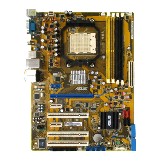
Page 25: Motherboard Layout
PCI1 ALC883 SPDIF_OUT SB600 PCIEX1_2 AAFP PCI2 CR2032 3V CLRTC Lithium Cell CMOS Power BIOS PCI3 USBPW7-10 SB_PWR FLOPPY USB910 PANEL CHA_FAN1 USB78 CHASSIS Refer to 2.7 Connectors for more information about rear panel connectors and internal connectors. ASUS M3A... -
Page 26: Layout Contents
2.2.4 Layout contents Slots Page DDR2 DIMM slots 2-11 PCI slots 2-18 PCI Express x1 slots 2-18 PCI Express 2.0 x16 slot 2-18 Jumper Page Clear RTC RAM (3-pin CLRTC) 2-19 USB device wake-up (3-pin USBPW1-4, USBPW56) 2-20 Keyboard power (3-pin KBPWR) 2-20 Rear panel connectors Page... - Page 27 System panel connector (20-8-pin PANEL) 2-31 • System power LED (2-pin PLED) • Hard disk drive activity LED (2-pin IDE_LED) • System warning speaker (4-pin SPEAKER) • ATX power button/soft-off button (2-pin PWRSW) • Reset button (2-pin RESET) ASUS Q-Connector(system panel) 2-32 ASUS M3A...
-
Page 28: Central Processing Unit (Cpu)
Central Processing Unit (CPU) The motherboard comes with an AM2+/AM2 socket designed for AMD Socket ® AM2+ Phenom™ FX / Phenom X4 / Phenom X2 / Athlon™ 64 X2 / Sempron™ processor or for Socket AM2 Athlon 64 X2 / Athlon 64 FX / Athlon 64 / Sempron processor. - Page 29 When the CPU is in place, push down the socket lever to secure the CPU. The lever clicks on the side tab to indicate that it is locked. Install a CPU heatsink and fan following the instructions that came with the heatsink package. ASUS M3A...
-
Page 30: Installing The Heatsink And Fan
2.3.2 Installing the heatsink and fan The AMD Phenom™ FX / Phenom X4 / Phenom X2 / Athlon™ 64 X2 / Athlon 64 ® FX / Athlon 64 / Sempron™ processor requires a specially designed heatsink and fan assembly to ensure optimum thermal condition and performance. Make sure that you use only AMD-certified heatsink and fan assembly. - Page 31 Push down the retention bracket lock on the retention mechanism to secure the heatsink and fan to the module base. ASUS M3A...
- Page 32 When the fan and heatsink assembly is in place, connect the CPU fan cable to the connector on the motherboard labeled CPU_FAN. CPU_FAN ® M3A CPU fan connector • Do not forget to connect the CPU fan connector! Hardware monitoring errors can occur if you fail to plug this connector.
-
Page 33: System Memory
DDR2 DIMMs into the DIMM sockets. Recommended Memory Configurations Sockets Mode DIMM_A1 DIMM_A2 DIMM_B1 DIMM_B2 (yellow) (black) (yellow) (black) – – Populated – Single-Channel Populated – – – Dual-channel (1) Populated – Populated – Dual-channel (2) Populated Populated Populated Populated ASUS M3A 2-11... - Page 34 Always use identical DDR2 DIMM pairs for dual channel mode. For optimum compatibility, it is recommended that you obtain memory modules from the same vendor. Visit the ASUS website (www.asus.com) for the latest Qualified Vendors list. Important notice on installing Windows XP 32-bit version ®...
- Page 35 Super Talent Heat-Sink Package T800UA12C4 Super Talent Heat-Sink Package T800UB1GC4 512MB NANYA NT5TU64M8BE-25C NANYA NT512T64U880BY-25C NANYA NT5TU64M8BE-25C NANYA NT1GT64U8HB0BY-25C NANYA NT5TU64M8CE-25D NANYA NT1GT64U8HCOBY-25D 512MB A3R12E3HEF641B9A05 AL6E8E63B8E1K A3R12E3HEF641B9A05 AL7E8E63B-8E1K 256MB TwinMOS E2508AB-GE-E ELPIDA 8G-24IK2-EBT Elixir N2TU51280BE-25C Elixir M2Y1G64TU8HB0B-25C ASUS M3A 2-13...
- Page 36 Dual-channel memory configuration. • C*: Supports 4 modules inserted into both the yellow and black slots as two pairs of Dual-channel memory configuration. Visit the ASUS website for the latest DDR2 QVL. 2-14 Chapter 2: Hardware information...
-
Page 37: Installing A Dimm
DIMM. Support the DIMM lightly with your fingers when pressing the retaining clips. The DIMM might DDR2 DIMM notch get damaged when it flips out with extra force. Remove the DIMM from the socket. ASUS M3A 2-15... -
Page 38: Expansion Slots
Expansion slots In the future, you may need to install expansion cards. The following sub-sections describe the slots and the expansion cards that they support. Make sure to unplug the power cord before adding or removing expansion cards. Failure to do so may cause you physical injury and damage motherboard components. -
Page 39: Interrupt Assignments
– – – – PCI slot 1 shared – – – – – – – PCI slot 2 – shared – – – – – – PCI slot 3 – – shared – – – – – ASUS M3A 2-17... -
Page 40: Pci Slots
2.5.4 PCI slots The PCI slots support cards such as a LAN card, SCSI card, USB card, and other cards that comply with PCI specifications. Refer to the figure below for the location of the slots. 2.5.5 PCI Express x1 slots This motherboard supports PCI Express x1 network cards, SCSI cards and other cards that comply with the PCI Express specifications. -
Page 41: Jumper
• Due to the chipset limitation, AC power off is required prior using C.P.R. function. You must turn off and on the power supply or unplug and plug the power cord before reboot the system. ASUS M3A 2-19... - Page 42 USB device wake-up (3-pin USBPW1-4, USBPW56) Set these jumpers to +5V to wake up the computer from S1 sleep mode (CPU stopped, DRAM refreshed, system running in low power mode) using the connected USB devices. Set to +5VSB to wake up from S3 and S4 sleep modes.
-
Page 43: Connectors
Side Speaker Out port (gray). This port connects the side speakers in an 8-channel audio configuration. Refer to the audio configuration table on the next page for the function of the audio ports in 2, 4, 6, or 8-channel configuration. ASUS M3A 2-21... - Page 44 Audio 2, 4, 6, or 8-channel configuration Headset Port 4-channel 6-channel 8-channel 2-channel Light Blue Line In Line In Line In Line In Lime Line Out Front Speaker Out Front Speaker Out Front Speaker Out Pink Mic In Mic In Mic In Mic In Orange...
-
Page 45: Internal Connectors
Pin 5 on the connector is removed to prevent incorrect cable connection when using a FDD cable with a covered Pin 5. ® FLOPPY PIN 1 NOTE: Orient the red markings on the floppy ribbon cable to PIN 1. M3A Floppy disk drive connector ASUS M3A 2-23... - Page 46 IDE connector (40-1 pin PRI_IDE) The onboard IDE connector is for the Ultra DMA 133/100/66 signal cable. There are three connectors on each Ultra DMA 133/100/66 signal cable: blue, black, and gray. Connect the blue connector to the motherboard’s IDE connector, then select one of the following modes to configure your device.
-
Page 47: Serial Ata Hard Disk Drive Connection
Connect the right-angle side of SATA signal cable to SATA device. Or you may connect the right-angle side of SATA cable to the onboard SATA port to avoid mechanical conflict with huge graphics cards. ASUS M3A 2-25... -
Page 48: Usb Connectors
Never connect a 1394 cable to the USB connectors. Doing so will damage the motherboard! You can connect the front panel USB cable to the ASUS Q-Connector (USB, blue) first, and then install the Q-Connector (USB) to the USB connector onboard if your chassis supports front panel USB ports. - Page 49 ® CHA_FAN1 M3A Fan connectors • Only the CPU_FAN and CHA_FAN 1 connectors support the ASUS Q FAN2 feature. • If you install two VGA cards, we recommend that you plug the rear chassis fan cable to the motherboard connector labled CHA_FAN1 for better themal environment.
- Page 50 Chassis intrusion connector (4-1 pin CHASSIS) This connector is for a chassis-mounted intrusion detection sensor or switch. Connect one end of the chassis intrusion sensor or switch cable to this connector. The chassis intrusion sensor or switch sends a high-level signal to this connector when a chassis component is removed or replaced.
- Page 51 • If you are uncertain about the minimum power supply requirement for your system, refer to the Recommended Power Supply Wattage Calculator at http://support.asus.com/PowerSupplyCalculator/PSCalculator. aspx?SLanguage=en-us for details. • The ATX 12 V Specification 2.0-compliant (500W) PSU has been tested...
- Page 52 Front panel audio connector (10-1 pin AAFP) This connector is for a chassis-mounted front panel audio I/O module that supports either HD Audio or legacy AC`97 audio standard. Connect one end of the front panel audio I/O module cable to this connector. AAFP HD Audio-compliant Legacy AC 97 audio...
-
Page 53: System Panel Connector
BIOS settings. Pressing the power switch for more than four seconds while the system is ON turns the system OFF. • Reset button (2-pin RESET) This 2-pin connector is for the chassis-mounted reset button for system reboot without turning off the system power. ASUS M3A 2-31... - Page 54 12. ASUS Q-Connector (system panel) You can use the ASUS Q-Connector to connect/disconnect chassis front panel cables in a few steps. Refer to the instructions below to install the ASUS Q- Connector. Connect the front panel cables to the ASUS Q-Connector.
-
Page 55: Chapter 3: Powering Up
This chapter describes the power up sequence, the vocal POST messages, and ways of shutting down the system. Powering up... -
Page 56: Starting Up For The First Time
Chapter summary Starting up for the first time ............3-1 Turning off the computer ............. 3-2 ASUS M3A... -
Page 57: Starting Up For The First Time
Check the jumper settings and connections or call your retailer for assistance. At power on, hold down the <Delete> key to enter the BIOS Setup. Follow the instructions in Chapter 4. ASUS M3A... -
Page 58: Turning Off The Computer
Turning off the computer 3.2.1 Using the OS shut down function ® If you are using Windows Click the Start button then select Turn Off Computer. Click the Turn Off button to shut down the computer. ® The power supply should turn off after Windows shuts down. -
Page 59: Chapter 4: Bios Setup
This chapter tells how to change the system settings through the BIOS Setup menus. Detailed descriptions of the BIOS parameters are also provided. BIOS setup... - Page 60 Chapter summary Managing and updating your BIOS ..........4-1 BIOS setup program ..............4-9 Main menu .................. 4-12 Advanced menu ................. 4-17 Power menu ................4-27 Boot menu .................. 4-31 Tools menu ................. 4-36 Exit menu ..................4-37 ASUS M3A...
-
Page 61: Managing And Updating Your Bios
ASUS Update (Updates the BIOS in Windows environment.) ® ASUS EZ Flash 2 (Updates the BIOS using a floppy disk or USB flash disk.) ASUS AFUDOS (Updates the BIOS using a bootable floppy disk.) ASUS CrashFree BIOS 3 (Updates the BIOS using a bootable floppy disk, USB flash disk or the motherboard support CD when the BIOS file fails or gets corrupted.) - Page 62 To update the BIOS through the Internet: Launch the ASUS Update utility from the Windows desktop by clicking Start ® > Programs > ASUS > ASUSUpdate > ASUSUpdate. The ASUS Update main window appears. Select Update BIOS from the Select the ASUS FTP site nearest...
- Page 63 To update the BIOS through a BIOS file: Launch the ASUS Update utility from the Windows desktop by clicking Start ® > Programs > ASUS > ASUSUpdate > ASUSUpdate. The ASUS Update main window appears. Select Update BIOS from a file option from the drop-down menu, then click Next.
-
Page 64: Creating A Bootable Floppy Disk
4.1.2 Creating a bootable floppy disk Do either one of the following to create a bootable floppy disk. DOS environment a. Insert a 1.44MB floppy disk into the drive. b. At the DOS prompt, type format A:/S then press <Enter>. Windows XP environment ®... -
Page 65: Asus Ez Flash 2 Utility
4.1.3 ASUS EZ Flash 2 utility The ASUS EZ Flash 2 feature allows you to update the BIOS without having to go through the long process of booting from a floppy disk and using a DOS-based utility. The EZ Flash 2 utility is built-in the BIOS chip so it is accessible by pressing <Alt>... -
Page 66: Afudos Utility
Updating the BIOS file To update the BIOS file using the AFUDOS utility: Visit the ASUS website (www.asus.com) and download the latest BIOS file for the motherboard. Save the BIOS file to a bootable floppy disk. Chapter 4: BIOS setup... - Page 67 A:\>afudos /iM3A.ROM The utility verifies the file and starts updating the BIOS. A:\>afudos /iM3A.ROM AMI Firmware Update Utility - Version 1.19(ASUS V2.07(03.11.24BB)) Copyright (C) 2002 American Megatrends, Inc. All rights reserved. WARNING!! Do not turn off power during flash BIOS Reading file ..
-
Page 68: Asus Crashfree Bios 3 Utility
4.1.5 ASUS CrashFree BIOS 3 utility The ASUS CrashFree BIOS 3 is an auto recovery tool that allows you to restore the BIOS file when it fails or gets corrupted during the updating process. You can update a corrupted BIOS file using the motherboard support CD, the floppy disk, or the USB flash disk that contains the updated BIOS file. -
Page 69: Bios Setup Program
The BIOS setup screens shown in this section are for reference purposes only, and may not exactly match what you see on your screen. • Visit the ASUS website (www.asus.com) to download the latest BIOS file for this motherboard. ASUS M3A... -
Page 70: Bios Menu Screen
4.2.1 BIOS menu screen Menu items Menu bar Configuration fields General help BIOS SETUP UTILITY Main Advanced Power Boot Tools Exit Use [ENTER], [TAB] System Time [15:13:25] or [SHIFT-TAB] to System Date [Thu 09/20/2007] select a field. Legacy Diskette A [1.44M, 3.5 in] Use [+] or [-] to configure system Time. -
Page 71: Menu Items
Up/Down arrow keys or <Page Up> /<Page Down> keys to display the other items on the screen. 4.2.9 General help Pop-up window At the top right corner of the menu screen Scroll bar is a brief description of the selected item. ASUS M3A 4-11... -
Page 72: Main Menu
Main menu When you enter the BIOS Setup program, the Main menu screen appears, giving you an overview of the basic system information. Refer to section 4.2.1 BIOS menu screen for information on the menu screen items and how to navigate through them. BIOS SETUP UTILITY Main Advanced... -
Page 73: Primary Ide Master/Slave
When set to [Disabled], the data transfer from and to the device occurs one sector at a time. Configuration options: [Disabled] [Auto] PIO Mode [Auto] Selects the PIO mode. Configuration options: [Auto] [0] [1] [2] [3] [4] ASUS M3A 4-13... -
Page 74: Sata1/2/3/4
DMA Mode [Auto] Selects the DMA mode. Configuration options: [Auto] [SWDMA0] [SWDMA1] [SWDMA2] [MWDMA0] [MWDMA1] [MWDMA2] [UDMA0] [UDMA1] [UDMA2] [UDMA3] [UDMA4] [UDMA5] SMART Monitoring [Auto] Sets the Smart Monitoring, Analysis, and Reporting Technology. Configuration options: [Auto] [Disabled] [Enabled] 32Bit Data Transfer [Disabled] Enables or disables 32-bit data transfer. -
Page 75: Storage Configuration
Enables or disables OnChip SATA Channel. Configuration options: [Disabled] [Enabled] OnChip SATA Type [IDE] This item appears only when you set the OnChip SATA Channel item to [Enabled]. Allows you to set the OnChip SATA Type. Configuration options: [IDE] [RAID] [AHCI] ASUS M3A 4-15... -
Page 76: System Information
4.3.7 System Information This menu gives you an overview of the general system specifications. The BIOS automatically detects the items in this menu. BIOS SETUP UTILITY Main AMIBIOS Version :0111 Build Date :10/05/07 Processor Type :AMD Athlon(tm) 64 Processor 3500+ Speed :2200MHz Count... -
Page 77: Advanced Menu
Allows selection of CPU overclocking options to achieve desired CPU internal frequency. Select any one of the preset overclocking configuration options: Manual Allows you to individually set overclocking parameters. Auto Loads the optimal settings for the system. Standard Loads the standard settings for the system.performance. ASUS M3A 4-17... - Page 78 The following two items appear only when you set the Ai Overclocking item to [Manual]. FSB Frequency [XXX] Displays the frequency sent by the clock generator to the system bus and PCI bus. Use the <+> and <-> keys to adjust the FSB frequency. You can also type the desired FSB frequency using the numeric keypad.
-
Page 79: Dram Timing Configuration
Allows selection of the DRAM Frequency programming method. Configuration options: [Auto] [Limit] [Manual] Memclock Value [533 MHz] This sub-item appears only when you set the Memory Clock Mode item to [Limit] and [Manual]. Configuration options: [533 MHz] [667 MHz] [800 MHz] [1066 MHz] ASUS M3A 4-19... -
Page 80: Ai Net 2
2T Mode [Auto] Allows selection of the 2T Mode. Configuration options: [Auto] [Disabled] [Enabled] DRAM Timing Mode [Auto] Allows selection of the DRAM Timing Mode. Configuration options: [Auto] [DCT 0] The following sub-items appear only when you set the DRAM Timing Mode item to [DCT 0]. -
Page 81: Cpu Configuration
Bank Interleaving [Auto] MemClk Tristate C3/ATLVID [Disabled] Memory Hole Remapping [Disabled] Power Down Enable [Enabled] Power Down Mode [Channel] Select Screen Select Item Change Option General Help Save and Exit Exit v02.61 (C)Copyright 1985-2007, American Megatrends, Inc. ASUS M3A 4-21... -
Page 82: Chipset
Bank Interleaving [Auto] Allows you to enable or disable the bank memory interleaving. Configuration options: [Disabled] [Auto] MemClk Tristate C3/ATLVID [Disabled] Allows you to enable or disable MemClk Tri-Stating during C3 and Alt VID. Configuration options: [Disabled] [Enabled] Memory Hole Remapping [Enabled] Allows you to enable or disable memory remapping around memory hole. -
Page 83: Hyper Transport Configuration
Isochronous Flow-Control Mode [Disabled] Configuration options: [Disabled] [Enable] HT Link Tristate [Disabled] Configuration options: [Disabled] [CAD/CTL] [CAD/CTL/CLK] UnitID Clumping [Disabled] Configuration options: [Disabled] [UnitID 2/3] [UnitID B/C] [UnitID 2/3&B/C] 2x LCLK Mode [Disabled] Configuration options: [Disabled] [Enable] ASUS M3A 4-23... -
Page 84: Onboard Devices Configuration
4.4.5 OnBoard Devices Configuration BIOS SETUP UTILITY Advanced Onboard Devices Configuraiton Allows BIOS to select Serial Port1 Base Addresses. Serial Port1 Address [3F8/IRQ4] HD Audio Azalia Device [Auto] Front Panel support Type [HD Audio] Onboard LAN [Enable] OnBoard NIC OPTROM [Disabled] Primary Display Adapter [PCI-E]... -
Page 85: Pci Pnp
PCI Latency timer [64] Configuration options: [32] [64] [96] [128] [160] [192] [224] [248] Allocate IRQ to PCI VGA [Yes] Configuration options: [Yes] [No Palette Snooping [Disabled] Configuration options: [Disabled] [Enabled] IRQ3/4/5/7/9/10/11/14/15 [PCI Device] Configuration options: [PCI Device] [Reserved] ASUS M3A 4-25... -
Page 86: Usb Configuration
4.4.7 USB Configuration The items in this menu allows you to change the USB-related features. Select an item then press <Enter> to display the configuration options. BIOS SETUP UTILITY Advanced USB Configuration Enables support for legacy USB. AUTO USB Devices Enabled: option disables None legacy support if... -
Page 87: Power Menu
Allows you to enable or disable the Advanced Configuration and Power Interface (ACPI) support in the Advanced Programmable Interrupt Controller (APIC). When set to Enabled, the ACPI APIC table pointer is included in the RSDT pointer list. Configuration options: [Disabled] [Enabled] ASUS M3A 4-27... -
Page 88: Apm Configuration
4.5.4 APM Configuration BIOS SETUP UTILITY Power APM Configuration Options Power Off Restore on AC Power Loss [Power Off] Power On Power On By PCI Devices [Disabled] Last State Power On By PCIE Devices [Disabled] Power On By External Modems [Disabled] Power On By RTC Alarm [Disabled]... -
Page 89: Hardware Monitor
(C)Copyright 1985-2007, American Megatrends, Inc. CPU Temperature [xxxºC/xxxºF] MB Temperature [xxxºC/xxxºF] The onboard hardware monitor automatically detects and displays the motherboard and CPU temperatures. Select [Ignored] if you do not wish to display the detected temperatures. ASUS M3A 4-29... - Page 90 CPU Fan / Chassis Fan / Power Fan Speed [xxxxRPM] or [Ignored] / [N/A] The onboard hardware monitor automatically detects and displays the fan speed in rotations per minute (RPM). If the fan is not connected to the motherboard, the field shows N/A.
-
Page 91: Boot Menu
These items specify the boot device priority sequence from the available devices. The number of device items that appears on the screen depends on the number of devices installed in the system. Configuration options: [1st FLOPPY DRIVE] [Hard Drive] [ATAPI CD-ROM] [Disabled] ASUS M3A 4-31... -
Page 92: Boot Settings Configuration
Configuration options: [Disabled] [Enabled] Full Screen Logo [Enabled] This allows you to enable or disable the full screen logo display feature. Configuration options: [Disabled] [Enabled] Set this item to [Enabled] to use the ASUS MyLogo2 feature. ™ AddOn ROM Display Mode [Force BIOS] Sets the display mode for option ROM. - Page 93 When set to Enabled, the system displays the message “Press DEL to run Setup” during POST. Configuration options: [Disabled] [Enabled] Chassis Intrusion [Enabled] Allows you to enable or disable the Chassis Intrusion function. Configuration options: [Disabled] [Enabled] ASUS M3A 4-33...
-
Page 94: Security
4.6.3 Security The Security menu items allow you to change the system security settings. Select an item then press <Enter> to display the configuration options. BIOS SETUP UTILITY Boot <Enter> to change Security Settings password. <Enter> again to Supervisor Password :Not Installed disabled password. -
Page 95: Change User Password
Password Check [Setup] When set to [Setup], BIOS checks for user password when accessing the Setup utility. When set to [Always], BIOS checks for user password both when accessing Setup and booting the system. Configuration options: [Setup] [Always] ASUS M3A 4-35... -
Page 96: Tools Menu
4.7.1 ASUS EZ Flash 2 Allows you to run ASUS EZ Flash 2. When you press <Enter>, a confirmation message appears. Use the left/right arrow key to select between [Yes] or [No], then press <Enter> to confirm your choice. Please see section 4.1.3 for details. -
Page 97: Exit Menu
Setup menus. When you select this option or if you press <F5>, a confirmation window appears. Select YES to load default values. Select Exit & Save Changes or make other changes before saving the values to the non-volatile RAM. ASUS M3A 4-37... - Page 98 4-38 Chapter 4: BIOS setup...
-
Page 99: Software Support
This chapter describes the contents of the support CD that comes with the motherboard package. Software support... - Page 100 Chapter summary Installing an operating system ........... 5-1 Support CD information .............. 5-1 Software informtion ..............5-9 RAID configurations ..............5-30 Creating a RAID driver disk ............5-38 ASUS M3A...
-
Page 101: Installing An Operating System
The contents of the support CD are subject to change at any time without notice. Visit the ASUS website(www.asus.com) for updates. 5.2.1 Running the support CD Place the support CD to the optical drive. The CD automatically displays the Drivers menu if Autorun is enabled in your computer. -
Page 102: Drivers Menu
The drivers menu shows the available device drivers if the system detects installed devices. Install the necessary drivers to activate the devices. ASUS InstAll - Drivers Installation Wizard Installs all of the drivers through the installation wizard. AMD Chipset Program Driver Installs the AMD Chipset drivers for the AMD 770 chipset. -
Page 103: Utilities Menu
This utility helps you keep your computer in healthy operating condition. ASUS Update The ASUS Update utility allows you to update the motherboard BIOS in Windows ® environment. This utility requires an Internet connection either through a network or an Internet Service Provider (ISP). -
Page 104: Make Disk Menu
Before using the ASUS Update, make sure that you have an Internet connection so that you can connect to the ASUS website. ATI WEBPAM Installs the ATI WebPAM RAID Utility. 5.2.4 Make Disk menu The Make Disk menu contains items to create the AMD 770 SATA/RAID driver disk. -
Page 105: Manual Menu
Reader from the Utilities menu before opening a user manual ® ® file. 5.2.6 ASUS Contact information Click the Contact tab to display the ASUS contact information. You can also find this information on the inside front cover of this user guide. ASUS M3A... -
Page 106: Other Information
5.2.7 Other information The icons on the top right corner of the screen give additional information on the motherboard and the contents of the support CD. Click an icon to display the specified information. Motherboard Info Displays the general specifications of the motherboard. Browse this CD Displays the support CD contents in graphical format. -
Page 107: Technical Support Form
Technical support Form Displays the ASUS Technical Support Request Form that you have to fill out when requesting technical support. Filelist Displays the contents of the support CD and a brief description of each in text format. ASUS M3A... -
Page 108: Software Information
5.3.1 ASUS MyLogo2™ The ASUS MyLogo2™ utility lets you customize the boot logo. The boot logo is the image that appears on screen during the Power-On Self-Tests (POST). The ASUS MyLogo2 is automatically installed when you install the ASUS Update utility from ™... - Page 109 Ratio box. When the screen returns to the ASUS Update utility, flash the original BIOS to load the new boot logo. 10. After flashing the BIOS, restart the computer to display the new boot logo during POST.
-
Page 110: Cool 'N' Quiet!™ Technology
5.3.2 Cool ‘n’ Quiet!™ Technology The motherboard supports the AMD Cool ‘n’ Quiet! Technology that dynamically ™ and automatically change the CPU speed, voltage, and amount of power depending on the task the CPU performs. Enabling Cool ‘n’ Quiet!™ Technology To enable Cool ‘n’... - Page 111 AMD ™ heatsink and fan assembly with monitor chip • If you purchased a separate heatsink and fan package, use the ASUS Q-Fan technology feature to automatically adjust the CPU fan speed according to your system loading. ASUS M3A...
- Page 112 ™ If you are using Windows XP and Vista, click the Start button. Select All ® Programs > ASUS > Cool & Quiet > Cool & Quiet vX.XXX. The Cool ‘n’ Quiet! technology screen appears and displays the current ™...
-
Page 113: Audio Configurations
Audio Manager icon on the taskbar. From the taskbar, double-click on the SoundEffect icon to display the Realtek HD Audio Manager. Realtek HD Audio Manager Realtek HD Audio Manager Exit button Configuration options Minimize button Control settings window Information button ASUS M3A 5-13... -
Page 114: Configuration Options
Information Click the information button ( ) to display information about the audio driver version, DirectX version, audio controller, audio codec, and language setting. Minimize Click the minimize button ( ) to minimize the window. Exit Click the exit button ( ) to exit the Realtek HD Audio Manager. - Page 115 Manager, click the Audio I/O tab. Click the drop-down menu to select the channel configuration. The control settings window displays the status of connected devices. Click for analog and digital options. Click <OK> to effect the Audio I/O settings and exit ASUS M3A 5-15...
- Page 116 Microphone The Microphone option allows you configure your input/output settings and to check if your audio devices are connected properly. To set the Microphone options: From the Realtek HD Audio Manager, click the Microphone tab. Click the Noise Suppression option button to reduce the static background noise when recording.
-
Page 117: Asus Pc Probe Ii
To launch the PC Probe II from the Windows desktop, click Start > All Programs ® > ASUS > PC Probe II > PC Probe II v1.xx.xx. The PC Probe II main window appears. After launching the application, the PC Probe II icon appears in the Windows ®... - Page 118 Button Function Opens the Configuration window Opens the Report window Opens the Desktop Management Interface window Opens the Peripheral Component Interconnect window Opens the Windows Management Instrumentation window Opens the hard disk drive, memory, CPU usage window Shows/Hides the Preference section Minimizes the application Closes the application Sensor alert...
- Page 119 Click to clicking the or buttons. You can increase also adjust the threshold values value using the Config window. Click to You cannot adjust the sensor decrease threshold values in a small value monitoring panel. ASUS M3A 5-19...
- Page 120 Monitoring sensor alert The monitor panel turns red when a component value exceeds or is lower than the threshold value. Refer to the illustrations below. Small display Large display WMI browser Click to display the WMI (Windows Management Instrumentation) browser. This browser displays various Windows®...
- Page 121 The left panel of the tab lists all logical drives. Click a hard disk drive to display the information on the right panel. The pie chart at the bottom of the window represents the used (blue) and the available HDD ASUS M3A 5-21...
- Page 122 Memory usage The Memory tab shows both used and available physical memory. The pie chart at the bottom of the window represents the used (blue) and the available physical memory. Configuring PC Probe II Click to view and adjust the sensor threshold values. The Config window has two tabs: Sensor/Threshold and Preference.
-
Page 123: Asus Ai Gear 2
5.3.5 ASUS AI Gear 2 ASUS AI Gear 2 provides four system performance options that allows you to select the best performance setting for your computing needs. This easy-to-use utility adjusts the processor frequency and vCore voltage to minimize system noise and power consumption. -
Page 124: Asus Ai Nap
5.3.6 ASUS AI Nap This feature allows you to minimize the power consumption of your computer whenever you are away. Enable this feature for minimum power consumption and a more quiet system operation. After installing AI Suite from the bundled support CD, you can launch the utility by double-clicking the AI Suite icon on the Windows OS taskbar and click the AI Nap button on the AI Suite main window. -
Page 125: Asus Q-Fan 2
5.3.7 ASUS Q-Fan 2 This ASUS Q-Fan 2 Control feature allows you to set the appropriate performance level of the CPU Q-Fan 2 or the Chassis Q-Fan 2 for more efficient system operation. After enabling the Q-Fan 2 function, the fans can be set to automatically adjust depending on the temperature, to decrease fan speed, or to achieve the maximum fan speed. -
Page 126: Raid Configurations
RAID configurations ® The motherboard comes with the AMD SB600 Southbridge RAID controller that allows you to configure Serial ATA hard disk drives as RAID sets. The motherboard supports the following RAID configurations. RAID 0 (Data striping) optimizes two identical hard disk drives to read and write data in parallel, interleaved stacks. -
Page 127: Amd ® Raid Configurations
In the Main Menu, go to Storage Configuration, and set the OnChip SATA Type item to [RAID]. Press <F10> to save the changes and exit. The RAID BIOS setup screens shown in this section are for reference only, and may not exactly match the items on your screen. ASUS M3A 5-27... - Page 128 ® FastBuild™ Utility ® To enter the AMD FastBuild™ utility: Boot up your computer. Press <Ctrl+F> during POST to display the main menu of the utility. FastBuild (tm) Utility (c) 2004-2005 AMD Technology, Inc. [ Main Menu ] View Drive Assignments..[1] Define LD.....[2] Delete LD.....[3] Controller Configuration..[4]...
- Page 129 ---- ---- ---- ---- LD 5 ---- ---- ---- ---- LD 6 ---- ---- ---- ---- LD 7 ---- ---- ---- ---- LD 8 ---- ---- ---- ---- [ Keys Available ] [↑]Up [↓]Down [ESC]Exit [Enter] Select ASUS M3A 5-29...
- Page 130 Creating a RAID 1 configuration To create a RAID 1 set: In the Main Menu, press <2> to enter the “Define LD” function. Press <Enter>, and the following screen appears. FastBuild (tm) Utility (c) 2004-2005 AMD Technology, Inc. [ Define LD Menu ] LD No RAID Mode Total Drv...
- Page 131 ---- ---- ---- ---- LD 5 ---- ---- ---- ---- LD 6 ---- ---- ---- ---- LD 7 ---- ---- ---- ---- LD 8 ---- ---- ---- ---- [ Keys Available ] [↑]Up [↓]Down [ESC]Exit [Enter] Select ASUS M3A 5-31...
-
Page 132: Deleting A Raid Configuration
Deleting a RAID configuration To create a RAID set: In the Main Menu, press <3> to enter the “Delete LD” function. Select the RAID item you want to delete and press <Del> or <Alt+D>. FastBuild (tm) Utility (c) 2004-2005 AMD Technology, Inc. [ Delete LD Menu ] LD No RAID Mode... -
Page 133: Creating A Raid Driver Disk
During the OS installation, the system prompts you to press the F6 key to install third-party SCSI or RAID driver. Press <F6> then insert the floppy disk with RAID driver into the floppy disk drive. Follow the succeeding screen instructions to complete the installation. ASUS M3A 5-33... - Page 134 5-34 Chapter 5: Software support...
Need help?
Do you have a question about the M3A - Motherboard - ATX and is the answer not in the manual?
Questions and answers