Table of Contents
Advertisement
Introduction.................................................................................................................................................1
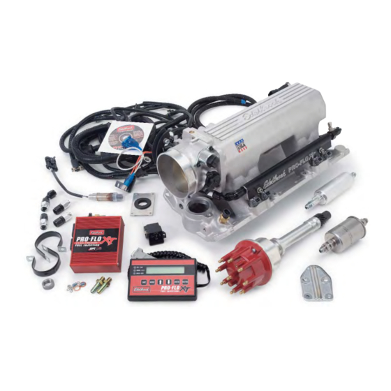
Components................................................................................................................................................2
Preliminaries...............................................................................................................................................3
Fuel System ................................................................................................................................................6
Induction System ......................................................................................................................................10
Sensors ....................................................................................................................................................13
O2 Sensor Installation ...............................................................................................................................15
Main System Harness ...............................................................................................................................16
Ignition System .........................................................................................................................................25
Other Applications.................................................................................................................................... 26
Software Installation .................................................................................................................................28
Calibration Selection .................................................................................................................................29
System Start-Up........................................................................................................................................30
Electronic Engine Management .................................................................................................................33
Pro-Flo Quick Tuning Guide.......................................................................................................................34
Calibration Module Flowchart ....................................................................................................................36
Parts and Part Numbers ............................................................................................................................37
Service & Warranty ...................................................................................................................................39
Thank you for selecting the Edelbrock Pro-Flo XT Fuel Injection System. This Multi-Point Fuel Injection System has been designed for 350 c.i.d.
small-block Chevrolet engines, and is designed to provide excellent performance, fuel economy, and maintenance-free operation. Installation of
the Edelbrock Pro-Flo XT Fuel Injection System involves modifications to the fuel system, ignition system, induction system, and possibly the
valve train. Although there are steps that must take place before others, the modifications do not necessarily have to be performed in a particular
order. Each modification is described in a separate section in this manual. Please study these instructions carefully before beginning installation
of any part of the Pro-Flo XT system.
EFI Technical Hotline at (800) 416-8628, 7am-5pm PST, Monday-Friday
Catalog #3527, #3528
Rev. 8/08 - AJ/mc
TABLE OF CONTENTS
Part #3527 and #3528
If you have any questions, do not hesitate to call our
E-mail: EFItech@edelbrock.com
Pro-Flo EFI Installation Instructions
INTRODUCTION
1
©2008 Edelbrock Corporation
Brochure No. 63-3527
Advertisement
Table of Contents

Related Manuals for Edelbrock PRO-FLO XT 3527


Summary of Contents for Edelbrock PRO-FLO XT 3527
-
Page 1: Table Of Contents
Service & Warranty ...39 Thank you for selecting the Edelbrock Pro-Flo XT Fuel Injection System. This Multi-Point Fuel Injection System has been designed for 350 c.i.d. small-block Chevrolet engines, and is designed to provide excellent performance, fuel economy, and maintenance-free operation. Installation of the Edelbrock Pro-Flo XT Fuel Injection System involves modifications to the fuel system, ignition system, induction system, and possibly the valve train. -
Page 2: Components
OEM pieces. In the event that one of these parts needs to be replaced, you are likely to find a replacement at your local parts supplier, in addition to your local Edelbrock dealer or directly from Edelbrock. For a list of part numbers, refer to the PART NUMBERS section at the back of this manual. -
Page 3: Tools And Equipment
Check all internal manifold passages with a light and wire, making sure they are clean and unobstructed. Check automatic transmission shift points before removal of your stock manifold and adjust linkage after Edelbrock manifold installation for same shift points (if needed). -
Page 4: Emission Controls
If you have insufficient clearance, a hood scoop may solve the problem. EMISSION CONTROLS The Edelbrock Pro-Flo XT system will not accept stock emissions control systems. Check local laws for requirements before installing the Pro-Flo system. Not legal on pollution-controlled motor vehicles. -
Page 5: Fuel Requirements
Pro-Flo system has been installed. Incorrect shift points can result in transmission damage. ENGINE CLEANING Edelbrock recommends that the Pro-Flo XT system be installed on a clean engine in order to prevent dirt from falling into the engine lifter valley or intake ports. -
Page 6: Fuel Pump And Filter
Because your Edelbrock Pro-Flo XT system controls fuel delivery very differently than a carburetor, some conversions to your fuel system are necessary. Pro-Flo XT electronic fuel injection requires high and constant fuel volume and fuel pressure. For this reason, a good primary fuel line is critical. - Page 7 NOTE: Whichever method you use to install the return fuel line, be careful to keep the end of the line away from the fuel pickup, as shown. Otherwise, aerated return fuel can be drawn into the pickup. Pro-Flo EFI Installation Instructions ©2008 Edelbrock Corporation Brochure No. 63-3527...
- Page 8 Bend the end of the return line away from the sock on the end of the fuel pickup line. Solder or weld the return hard line to the fuel pickup line. HARD RETURN LINE METHOD Catalog #3527, #3528 ©2008 Edelbrock Corporation Rev. 8/08 - AJ/mc Pro-Flo EFI Installation Instructions Brochure No. 63-3527...
-
Page 9: Fuel System Installation
2 seconds each time. Check the entire fuel system for leaks. Refer to the SYSTEM START-UP section of this manual for details. Catalog #3527, #3528 Rev. 8/08 - AJ/mc Pro-Flo EFI Installation Instructions ©2008 Edelbrock Corporation Brochure No. 63-3527... -
Page 10: Fuel Rails
The Edelbrock Pro-Flo XT system delivers fuel and air to the engine via the induction system consisting primarily of a manifold, 90mm air valve, fuel rails, and fuel injectors. The induction system is fully assembled, tested, seal checked, and flowed at the factory and is as easy to install as a manifold. -
Page 11: Pre-Installation
Do not use this port for a coolant temperature sensor since the reduced orifice size may prevent an accurate reading. Catalog #3527, #3528 Rev. 8/08 - AJ/mc Pro-Flo EFI Installation Instructions ©2008 Edelbrock Corporation Brochure No. 63-3527... - Page 12 Edelbrock recommends the use of Loctite 598 OEM High Temperature Silicone Gasket instead of end seal gaskets. Apply a 1/4-inch thick bead of sealant across each end seal surface, overlapping the intake gasket at the four corners (NOTE: Use the recommended silicon sealer.
-
Page 13: Manifold Absolute Pressure Sensor
The Edelbrock Pro-Flo XT system interprets overall engine operating conditions and fuel/spark requirements based on readings from sensors that measure specific engine conditions. The Pro-Flo system includes five sensors: 1) Manifold Absolute Pressure 2) Manifold Air Temperature 3) Coolant Temperature... -
Page 14: Throttle Position Sensor
Catalog #3527, #3528 Rev. 8/08 - AJ/mc Pro-Flo EFI Installation Instructions THROTTLE POSITION SENSOR The Throttle Position Sensor, an integral part of the Pro-Flo throttle body, measures throttle angle. ©2008 Edelbrock Corporation Brochure No. 63-3527... -
Page 15: O2 Sensor Installation
Check to ensure SENSOR HAS BEEN INSTALLED. O2 SELECT JUMPER INSTALL FOR WIDEBAND (OPTIONAL) Pro-Flo EFI Installation Instructions O2 SENSOR SELECT O2 SELECT JUMPER CAP INSTALL FOR NARROW BAND (INCLUDED IN KIT) ©2008 Edelbrock Corporation Brochure No. 63-3527... - Page 16 Catalog #3527, #3528 ©2008 Edelbrock Corporation Rev. 8/08 - AJ/mc Pro-Flo EFI Installation Instructions Brochure No. 63-3527...
-
Page 17: Main System Harness
MAIN SYSTEM HARNESS This diagram illustrates the chassis side of the Pro-Flo XT Main System Harness. Catalog #3527, #3528 ©2008 Edelbrock Corporation Rev. 8/08 - AJ/mc Pro-Flo EFI Installation Instructions Brochure No. 63-3527... - Page 18 Catalog #3527, #3528 ©2008 Edelbrock Corporation Rev. 8/08 - AJ/mc Pro-Flo EFI Installation Instructions Brochure No. 63-3527...
- Page 19 MAIN SYSTEM HARNESS This diagram illustrates the engine side of the Pro-Flo XT Main System Harness. Catalog #3527, #3528 ©2008 Edelbrock Corporation Rev. 8/08 - AJ/mc Pro-Flo EFI Installation Instructions Brochure No. 63-3527...
- Page 20 Catalog #3527, #3528 ©2008 Edelbrock Corporation Rev. 8/08 - AJ/mc Pro-Flo EFI Installation Instructions Brochure No. 63-3527...
-
Page 21: Installation
Inspect the Main System Harness, making sure that all connectors and grounds are properly in place. Edelbrock strongly recommends mounting the Pro-Flo XT ECU in the passenger compartment to protect it from possible damage. A 37-pin bulkhead connector has been supplied to simplify wire routing. Mounting this connector will require drilling an 1-1/2” hole in the firewall, along with four 3/16”... -
Page 22: Engine Harness
Pro-Flo EFI Installation Instructions J6: Ignition Coil Coil Connectors J19: Fuel Pump J18: O Sensor Ignition Harness J2: Customer Interface Sensor Select J3: Firewall Bulkhead Connector +12v Switched Power J7: Calibration Module J8: PC Interface Chassis Harness ©2008 Edelbrock Corporation Brochure No. 63-3527... -
Page 23: Throttle Cable Installation
The Manifold Absolute Pressure sensor attaches to the The Throttle Position sensor attaches to the harness with Connector J5. The Manifold Air Temperature sensor attaches to the Pro-Flo EFI Installation Instructions harness with Connector J17. harness with Connector J16. ©2008 Edelbrock Corporation Brochure No. 63-3527... - Page 24 This sleeve prevents the clamp from shorting the fuel pump terminals. B L K O R N Catalog #3527, #3528 Rev. 8/08 - AJ/mc IGNITION HARNESS GROUND TO REAR CYL HEAD Pro-Flo EFI Installation Instructions RED (COIL +) BROWN (COIL -) ©2008 Edelbrock Corporation Brochure No. 63-3527...
-
Page 25: Ignition System
Catalog #3527, #3528 Rev. 8/08 - AJ/mc IGNITION SYSTEM Pro-Flo EFI Installation Instructions NOTE: The red and brown wires should be the only coil connections. Do not add another switched power wire to the positive terminal. ©2008 Edelbrock Corporation Brochure No. 63-3527... -
Page 26: Typical Installation
The Pro-Flo XT system has been designed and calibrated specifically using the Chevrolet 350 c.i.d. Small-block with large-valve style cylinder heads (such as Edelbrock’s Performer RPM Street Cylinder Heads with 2.02-inch valves) and tubular headers as a baseline. It is unlikely that every engine on which the Pro-Flo XT system is installed will match this baseline combination. The system can be used with similar applications, as long as the necessary fuel calibration adjustments are made. - Page 27 Clean 5 volt reference for use with most three wire analog sensors Oil pressure sensor input to ECU. Use with VRef and Sensor Gnd. Recommend Edelbrock P/N 36011, 0-100 psig pressure sensor. Fuel pressure sensor input to ECU. Use with VRef and Sensor Gnd.
-
Page 28: Installing The Software
It allows Edelbrock tech support personnel to view your ECU data real time using the iLink feature (internet connection required) • It allows you to send your existing calibration file to Edelbrock tech support personnel using the iLink feature (internet connection required). •... - Page 29 Starting with the correct calibration file will reduce the amount of tuning needed. NOTE: Edelbrock recommends a minimum of 112° for intake lobe seperation angle on all Pro-Flo EFI applications. A value less...
-
Page 30: System Start-Up
Once the Edelbrock Pro-Flo system has been installed, there are a few procedures you must follow to break-in the system. Carefully performing these break-in procedures will ensure best results and optimal performance. Use this checklist to double-check the following areas BEFORE starting the car: ❑... - Page 31 MODE = S C R O L L E N T E R Base Tim'g set: OFF MODE Pro-Flo EFI Installation Instructions = S C R O L L E N T E R ©2008 Edelbrock Corporation Brochure No. 63-3527...
- Page 32 • Set IDLE CONTROL ON. Set TARGET IDLE to the same RPM established by the idle stop screw. • Save calibration settings to “A” Catalog #3527, #3528 Rev. 8/08 - AJ/mc ® system. Pro-Flo EFI Installation Instructions ©2008 Edelbrock Corporation Brochure No. 63-3527...
-
Page 33: Electronic Engine Management
ELECTRONIC ENGINE MANAGEMENT The Edelbrock Pro-Flo system uses the Speed-Density method of electronic engine management, in which fuel and spark requirements are based on engine speed (RPM) and engine load (manifold pressure and temperature). The Electronic Control Unit (ECU) receives signals regarding engine speed (from the distributor), and the three load factors consisting of coolant temperature (ECT), Manifold Absolute Pressure (MAP) and air temperature (MAT). -
Page 34: Pro-Flo Quick Tuning Guide
ENGINE RPM 1000 2000 3000 4000 5000 Problem Area LEAN Pro-Flo EFI Installation Instructions 7000 In this example, tune by adding 10% fuel at each area marked by an “X”, surrounding the problem area. ©2008 Edelbrock Corporation Brochure No. 63-3527... - Page 35 System Editor icon shown below. The engine controllers included in the Edelbrock Pro Flo system CANNOT be edited live using the System Editor software. In other words, System Editor can only be used to edit the calibration file loaded in the software. You cannot directly edit the calibration file loaded into the ECU. When you make changes to a calibration file, it must be saved and flashed into your ECU’s memory before those changes take effect.
- Page 36 CALIBRATION MODULE DIAGRAM Catalog #3527, #3528 ©2008 Edelbrock Corporation Rev. 8/08 - AJ/mc Pro-Flo EFI Installation Instructions Brochure No. 63-3527...
-
Page 37: Part Numbers
Many of the components of the Pro-Flo system are available separately. Many are standard OEM parts. In the event that one of these parts need to be replaced, you are likely to find a replacement at your local parts supplier, in addition to your local Edelbrock dealer or directly from Edelbrock. - Page 38 ( 2) 1/4”-20 x .5” hex flange screw ( 1) Fuel regulator nut ( 1) MAT sensor grommet ( 1) 45° fitting ( 2) -6 fuel pump fitting ( 1) -6 to 3/8” pipe adapter Pro-Flo EFI Installation Instructions ©2008 Edelbrock Corporation Brochure No. 63-3527...
-
Page 39: Service & Warranty
In the event that your Edelbrock Pro-Flo System should need servicing, return the unit pre-paid to the Edelbrock Service and Repair facility at 2700 California Street, Torrance, CA 90503. Do not attempt to disassemble or service the components of the Pro-Flo system yourself. Doing so may void the warranty.
Need help?
Do you have a question about the PRO-FLO XT 3527 and is the answer not in the manual?
Questions and answers