Table of Contents
Advertisement
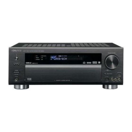
AUDIO VIDEO SURROUND RECEIVER
KRF - X9090D
INSTRUCTION MANUAL
About the supplied remote control
Compared to standard remote controls, the remote control supplied with this model has several
operation modes. These modes enable the remote control unit to control other audio/video components.
In order to effectively use the remote control it is important to read the operating instructions and obtain
a proper understanding of the remote control and how to switch its operation modes (etc.).
Using the remote control without completely understanding its design and how to switch the operation
modes may result in incorrect operations.
B60-5561-10 01 CS
(E,X)
OC
0504
Advertisement
Table of Contents

Related Manuals for Kenwood KRF-X9090D


Summary of Contents for Kenwood KRF-X9090D
- Page 1 AUDIO VIDEO SURROUND RECEIVER KRF - X9090D INSTRUCTION MANUAL About the supplied remote control Compared to standard remote controls, the remote control supplied with this model has several operation modes. These modes enable the remote control unit to control other audio/video components. In order to effectively use the remote control it is important to read the operating instructions and obtain a proper understanding of the remote control and how to switch its operation modes (etc.).
-
Page 2: Before Applying The Power
Caution : Read this page carefully to ensure safe Before applying the power operation. How to use this manual Units are designed for operation as follows. U.S.A. and Canada ........... AC 120 V only This manual is divided into four sections, Preparations, Operations, Australia ............ -
Page 3: Table Of Contents
Connecting the antennas ......... 18 Preparing for surround sound ....... 19 Before setting up the speakers ....... 19 Setting up the speakers automatically (AUTO SETUP) “Kenwood Room Acoustic Calibration” .... 20 Setting up the speakers manually (MANUAL SETUP) ........... 22 Other settings ..........24 Normal playback .......... -
Page 4: Unpacking
If the unit was shipped to you directly, (Approx.) notify your shipper immediately. Kenwood recommends that you retain the original carton and packing materials in case you need to move or ship the unit in the future. -
Page 5: Special Features
• DTS 96/24 • DTS • DSP Mode Kenwood Room Acoustic Calibration Without going through a complicated manual setup procedure, this function automatically measures the capacity of your speaker system, speaker layout and acoustic specifications of your listening room correctly with the provided microphone, and provides the best listening environment. -
Page 6: Names And Functions Of Parts
Names and functions of parts Main unit CLIP Input mode Listen mode indicators MUTE Speaker indicator indicators SLEEP indicator indicator RDS indicators indicators Input channel MUTE DIGITAL DOLBY DIGITAL EX DTS 96/24 DOLBY H STEREO NEO:6 indicators AUTO DETECT AUTO indicator DOLBY EX ES MATRIX6.1 DOLBY VS... -
Page 7: Components
Names and functions of parts Remote control unit This remote control unit can be used not only for Kenwood products but also for other non-Kenwood products by setting the appropriate manufacturer’s setup codes. 1 LCD (Liquid Crystal Display) TV key Shows the operation mode of the remote Use to turn the TV on or off. -
Page 8: Setting Up The System
Setting up the system Make connections as shown in the following pages. Input mode settings When connecting the related system components, be sure to refer to the instruction manuals supplied with the CD/DVD, VIDEO 2, VIDEO 3 and DVD/6CH inputs each include jacks components you are connecting. -
Page 9: Connecting The Terminals
Setting up the system Connecting the terminals 1 Strip coating. 2 Loosen. Speaker placement Center Speaker 3 Insert. 4 Secure. Subwoofer Front Speakers (L, R) Listening position Surround Speakers (L, R) Surround Back Surround Back Left Speaker Right Speaker • Never short circuit the + and – speaker cords. •... -
Page 10: Connecting A Dvd Player (6-Channel Input)
Setting up the system Connecting a DVD player (6-channel input) If you have connected a DVD player to this model with digital connection, be sure to read the “Input mode settings” section carefully. COAXIAL OPTICAL OPTICAL OPTICAL CD/DVD VIDEO 3 MONITOR VIDEO VIDEO... -
Page 11: Connecting Audio Components
Setting up the system Connecting audio components To AC wall outlet • The earth terminal with the H symbol is used for noise reduction of REC OUT PLAY IN record player. It is not PHONO CD/DVD MD/TAPE for safety earth. Cassette Deck or MD Recorder DVD Player or CD Player... -
Page 12: Connecting Video Components
Setting up the system Connecting video components S VIDEO Jacks About the S VIDEO Jacks S VIDEO S VIDEO S VIDEO S VIDEO S VIDEO S VIDEO S VIDEO VIDEO VIDEO VIDEO VIDEO VIDEO VIDEO Use the S VIDEO Jacks to make connections to video components with * DVD IN input jack is used for... -
Page 13: Digital Connections
Setting up the system Digital connections The digital in jacks can accept DTS, Dolby Digital, or PCM signals. Connect components capable of outputting DTS, Dolby Digital, or standard PCM (CD) format digital signals. If you have connected any digital components to this model, be sure to read the “Input mode settings” section carefully. COAXIAL OPTICAL OPTICAL... -
Page 14: Connecting Video Components
Setting up the system Connecting video components (COMPONENT VIDEO) If you have connected this model to a video component with COMPONENT jacks, you can get a better picture quality than by connecting to the S-VIDEO jacks. * DVD IN input jack is used for either CD/DVD input or DVD/ 6CH input. -
Page 15: Connecting The Speakers
Setting up the system Connecting the speakers Surround Back Speaker/s When connecting a single Surround Back Speaker, connect it to SURROUND BACK L terminals and se- lect “SB LARGEx1” or “SB NML/THXx1” at Speaker £ settings. Surround Speakers Right Left Left Right Powered... -
Page 16: Pre Out Connections
Setting up the system PRE OUT connections This receiver has additional PRE OUT jacks. These can be used for various purposes, but will need to be connected to an external power amplifier as shown in the example below. CENTER ROOM B FRONT SURROUND SURROUND BACK SUB WOOFER PRE OUT... -
Page 17: Connecting To Another Room (Room B)
Setting up the system Connecting to another room (ROOM B) This connection allows you to connect your main system to a monitor TV and speaker system located in another area (ROOM B). CENTER VIDEO ROOM B ROOM B FRONT SURROUND SURROUND BACK SUB WOOFER PRE OUT Front Speakers (Room B) -
Page 18: Connecting To The Av Aux Jacks
Setting up the system Connecting to the AV AUX jacks Connecting the antennas The AV AUX jacks are convenient for connection of video components The broadcast reception cannot be made unless the antennas are such as a camcorder or a video game. connected. -
Page 19: Preparing For Surround Sound
Preparing for surround sound Before setting up the speakers AUTO SETUP For the optimum surround playback, variety of speaker settings are necessary. Following the procedure below, go through the settings described in CALIBRATE further pages. START RETURN Measuring ERROR MESSAGE Analyzing WARNING COMPLETE... -
Page 20: Setting Up The Speakers Automatically (Auto Setup)
ENTER key to return to the "AUTO SETUP" display. night time. “Kenwood Room Acoustic Calibration” function automatically per- Notes forms the following adjustments with the provided microphone by •... - Page 21 Preparing for surround sound E01 : No MIC E99 : Error Microphone is not connected. Communication error occurred in the unit. Connect the provided microphone for setup to the SETUP MIC Try the calibration again. If the same message appears, consult jack.
-
Page 22: Setting Up The Speakers Manually
Preparing for surround sound Setting up the speakers manually (MANUAL SETUP) W06 : No Spk S Surround speakers are not connected. Select a speaker system. Connect a pair of Surround speakers if you have a set. If you have THX certified speakers, please set them to NML/THX. If there are no Surround speakers, no need to connect it. - Page 23 Preparing for surround sound 9 Use the MULTI CONTROL knob or MULTI %/fi keys to select 2 Press the 5/∞ keys or MULTI @/# keys for the following the appropriate Surround Speaker setting. displays: 1 T.TONE AUTO If you selected “FRNT LARGE” as the Front Speaker setting, : Adjust the volume level from each speaker by using test tone.
-
Page 24: Other Settings
Preparing for surround sound 3 Measure the distance from the listening position to each of Other settings the speakers. Jot down the distance to each of the speakers. Adjust the Subwoofer RE-MIX. Distance to Front Left Speaker (L) : ____ meters (feet) Distance to Center Speaker (C) : ____ meters (feet) 1 Press the 5/∞... - Page 25 Preparing for surround sound 2 Use the MULTI CONTROL knob or MULTI %/fi keys to select 1 Press the 5/∞ keys or MULTI @/# keys to select the “AUDIO the distance between left and right Surround Back speaker. DELAY“ and press the MEMORY/ENTER key or the ENTER key.
-
Page 26: Normal Playback
Normal playback Listening to a source component Preparing for playback Some preparatory steps are needed before starting playback. (POWER ON/STANDBY) SPEAKERS INPUT MODE POWER ON/OFF Turning on the receiver 1 Turn on the power to the related components. 2 Turn on the power to this receiver by pressing the POWER ON/ OFF and (POWER ON/STANDBY) key. -
Page 27: Input Level Adjustment (Analog Sources Only)
Normal playback Input level adjustment (analog sources only) Adjusting the sound ACTIVE EQ mode Input level adjustment (analog sources only) If the input level of an analog source signal is too high, the CLIP indicator After completing "Setting up the speakers automatically (AUTO SETUP)", the most suitable equalizer curve for the frequency characteristics of will blink. - Page 28 Normal playback Adjusting the TONE One-touch low frequency emphasis (BASS BOOST) You can adjust the sound quality when the receiver is in the PCM stereo This setting can be made when the receiver is in the PCM stereo and and analog stereo mode, and both THX and Virtual mode are off. analog stereo mode, and both THX and Virtual mode are off.
-
Page 29: Recording
Recording Recording audio (analog sources) Recording music in REC MODE AUTO or MANUAL 1 Use the INPUT SELECTOR key or the Input Selector keys to select the source (CD/DVD, DVD/6CH, VIDEO 2, VIDEO 3) you want to record. 2 Set the MD or TAPE recorder to record. 3 Press and hold the DIMMER key for more than 2 seconds for the following selections;... -
Page 30: Listening To Radio Broadcasts
Listening to radio broadcasts Using RDS This model can store up to 40 stations in the memory and recall them by (Radio Data System) one-touch operation. Radio stations can be classified into RDS (Radio Data System) stations RDS is a system that transmits useful information (in the form of digital and other stations. -
Page 31: Presetting Radio Stations Manually
Listening to radio broadcasts Presetting radio stations manually Receiving preset stations The RDS auto memory function assigns preset numbers to RDS stations starting from preset number “1”. Therefore, be sure to execute the RDS auto memory function before using the following operations to manually store AM stations and other FM stations, and RDS stations. -
Page 32: Using The Rds Disp (Display) Key
Listening to radio broadcasts Using the RDS DISP (Display) key Presetting RDS stations (RDS AUTO MEMORY) This function automatically stores up to 40 RDS stations in the preset memory. In order to use the PTY function, the RDS stations must be stored in the preset memory using the RDS AUTO MEMORY function. -
Page 33: Tuning By Program Type (Pty Search)
Listening to radio broadcasts Tuning by Program TYpe Press the PTY key to start searching. (PTY search) EXAMPLE : Searching for a Pop Music broadcast. This function lets you set the tuner to automatically search for stations which are currently broadcasting the type of program (genre) you want Display while searching. -
Page 34: Ambience Effects
Ambience effects This receiver is equipped with listening modes that allow you to enjoy an enhanced sonic ambience with a variety of video sources. In order to obtain the optimum effect from the surround modes, make sure to input the proper speaker settings beforehand. Surround modes The below image is for 5.1 channel surround The below image is for 6.1 channel surround... - Page 35 Ambience effects Dolby Digital Dolby Virtual Speaker The Dolby Digital surround format lets you enjoy up to 5.1 The Dolby Virtual Speaker features a virtual surround sound field. channels of digital surround sound from Dolby Digital program This implements an effect as if there are multiple speakers in the sources (such as Laserdisc or DVD software marked listening room.
- Page 36 Ambience effects ASA (Advanced Speaker Array) THX is an exclusive set of standards and technologies established by ASA is a proprietary THX technology which processes the sound fed the world-renowned film production company, Lucasfilm Ltd. THX to 2 side and 2 back surround speakers to provide the optimal grew from George Lucas' personal desire to make your experience of surround sound experience.
-
Page 37: Surround Play
Ambience effects Surround play Each turn of the LISTEN MODE knob or press of the LISTEN MODE % / fi keys switches the setting as listed below. DTS can be used when playing CD, DVD or LD software carrying the DTS The listening mode settings are different depending on the type mark. - Page 38 Ambience effects = DTS 96/24+THX MusicMode : DTS 96/24 +THX MusicMode*3 Switching the LISTEN mode to Stereo temporarily ~ DTS+THX Select2 Cinema : DTS+THX Select2 Cinema*4 ! DTS 96/24+THX Select2 Cinema : DTS 96/24+THX Select2 Pressing the STEREO key changes the currently selected LISTEN mode Cinema*4 into Stereo.
-
Page 39: Virtual Modes
Ambience effects Virtual modes DVD 6-channel playback The following modes allow you to enjoy astonishing ambience effect Using a DVD player or the like equipped with six (5.1) output channels and even when you use only two speakers or listen through headphones. the receiver, you can enjoy surround sound playback. -
Page 40: Adjusting The Sound
Ambience effects Adjusting the sound Midnight mode (Dolby Digital and DTS mode only) You can make further adjustments to the sound while listening to When watching movies at night , you might not be able to raise the volume as loud as normal. - Page 41 Ambience effects Dimension mode (Pro Logic II x Music mode and Pro Logic II Center Image mode (Neo:6 Music mode only) Music mode only) In the CENTER IMAGE setting mode of the Neo:6 Music listen mode, it is possible to enhance the center channel audio by adjusting the center When listening to music with certain recordings, you will also be able to achieve signal component.
-
Page 42: Convenient Functions
Convenient functions Display dimmer adjustment Sleep timer The dimmer function lets you select the brightness of the receiver's The sleep timer function turns the receiver OFF (to the standby mode) display. You might find this useful if you darken your room to watch automatically when the set timer period has elapsed. -
Page 43: Searching For Your Codes
“Searching for your codes”, you may need to find out which four-digit DVD/6CH code is operating your equipment: CD/DVD CD and MD (Kenwood) For example, to find out which code is operating your TV: MD/TAPE CD and MD (Kenwood) Press the TV MODE key once. Next, press and hold the LEARN... -
Page 44: Re-Assigning Device Keys
Basic remote control operations for other components Re-assigning device keys Operating other components This operation lets you operate the registered components. The remote control can be setup to control second TV or VCR, or any combination of eight home entertainment components. For example, to control the operation of two different VCR using the remote control, the user need to re-assign the unused VIDEO 2 key to SOURCE... -
Page 45: Storing The Remote Control Code Of The Other Components
Basic remote control operations for other components Press and hold the LEARN key for 3 seconds until blinks Storing the remote control code of the other twice, then release the LEARN key. components Press the Numeric key to enter 9 , 7 , 5 . The remote control unit can store the remote control code of the other components and you can operate the other components from the remote Press any of the Source keys (DVD/6CH, VIDEO 1, VIDEO 2,... -
Page 46: Setup Code Chart
Baze 0672 Durabrand 0713 Kendo 0699, 0713 Beko 1153 0768 Kennex 0770 Bellagio 1004 Eclipse 0723, 0751 Kenwood 0490, 0534 Black Diamond 0713, 0766 Elin 0770 Kiiro 0770 Blue Sky 0651, 0672, 0695, 0713 Ellion 0850 Kiss 0665 Boghe 1004... - Page 47 Basic remote control operations for other components Setup code chart DVD player (continued) DVD player (continued) DVD player (continued) Maker Setup codes Maker Setup codes Maker Setup codes Micromega 0539 Rowa 0516, 0717, 0872, 1004 Tevion 0651, 0768, 1036 Microsoft 0522 Saba 0551, 0651...
- Page 48 Basic remote control operations for other components Setup code chart TV (continued) TV (continued) Maker Setup codes Maker Setup codes Maker Setup codes A.R. Systems 0374, 0455 Baur 0009, 0037, 0361, 0455, Continental Edison 0109, 0196, 0198, 0487 0512, 0535 Accent 0009 Cosmel...
- Page 49 Basic remote control operations for other components Setup code chart TV (continued) TV (continued) TV (continued) Maker Setup codes Maker Setup codes Maker Setup codes Euroman 0037, 0264, 0370 Grundig 0009, 0036, 0037, 0070, 0011, 0012, 0036, 0037, 0195, 0443, 0487, 0535, 0070, 0072, 0073, 0087, Europa 0037...
- Page 50 Basic remote control operations for other components Setup code chart TV (continued) TV (continued) TV (continued) Maker Setup codes Maker Setup codes Maker Setup codes Liesenkotter 0012, 0037, 0327, 0328 Mivar 0516, 0609 Otto Versand 0036, 0037, 0093, 0109, 0226, 0247, 0294, 0361, Lifetec 0009, 0037, 0218, 0374, Monaco...
- Page 51 Basic remote control operations for other components Setup code chart TV (continued) TV (continued) TV (continued) Maker Setup codes Maker Setup codes Maker Setup codes Radiomarelli 0037, 0087, 0516 Sharp 0036, 0093, 0193, 0200, Tashiko 0036, 0163 0294, 0516, 1193 RadioShack 0037, 0178 Tatung...
- Page 52 Basic remote control operations for other components Setup code chart TV (continued) HDTV Satellite Receiver Maker Setup codes Maker Setup codes Maker Setup codes Triad 0556 Hitachi 0719 @sat 1300 Trident 0516 @Sky 1334 Tristar 0193, 0218, 0264 ABsat 0123, 0832 Triumph 0346, 0516, 0556 0642, 1259...
- Page 53 0133, 0241, 0751 Eurosat 0243 Kathrein 0123, 0173, 0200, 0249, Opentel 1412 0658, 1221 Eurosky 0132, 0243, 0299, 0607 Optex 1043 Kenwood 0853 Eurostar 0607, 0880 Optus 0879 Key West 0132, 0243, 0794 Ferguson 0455, 0711, 1291 Orbitech 1099, 1100...
- Page 54 Basic remote control operations for other components Setup code chart Satellite Receiver (continued) Satellite Receiver (continued) Cable Converter Maker Setup codes Maker Setup codes Maker Setup codes Pino 1334 Supernova 0887 0003 Pioneer 0292, 0329, 0352, 0853, Tantec 0455 1063, 1269 1308 Tarbs 1225...
- Page 55 Basic remote control operations for other components Setup code chart Cable Converter (continued) VCR (Continued) Maker Setup codes Maker Setup codes Maker Setup codes Videotron 0250 Accent 0072 Craig 0037, 0072, 0240 Videoway 0250 Adyson 0072 Crown 0020, 0037, 0072, 0278, 0480 Visionetics 1064...
- Page 56 Kendo 0072, 0106, 0278, 0315, Samurai 0020 0315 0348, 0642 Sansei 0048 Nordmende 0041, 0067, 0320, 0321, Kenwood 0038, 0041, 0067 Sansui 0000, 0041, 0067, 0072, 0384, 0493 0106, 0348 0000 Oceanic 0000, 0041, 0048, 0081, Sanyo 0048, 0067, 0104, 0240,...
- Page 57 Setup codes Universum 0000, 0037, 0081, 0104, Smaragd 0348 0106, 0195, 0240, 0348, Genexxa 0037 Solavox 0020 1137 Kenwood 0028, 0037, 0190, 0339, Sonneclair 0072 Victor 0067 0523, 0677, 0681, 0826, Sontec 0037 Video Concepts 0045 0858, 0859, 1338, 1339,...
-
Page 58: Other Components' Operations
Refer to the following sections for details. • The key descriptions in this section are for representative components. These keys can be used to perform the basic operations of KENWOOD and other manufacturers’ components which the setup code for each component had been entered beforehand. - Page 59 Basic remote control operations for other components Refer to the following for the type of remote control operations available for each component. Satellite Receiver operation keys Cable converter operation keys...
- Page 60 Basic remote control operations for other components Refer to the following for the type of remote control operations available for each component. VCR operation keys CD player operation keys...
- Page 61 Basic remote control operations for other components Refer to the following for the type of remote control operations available for each component. MD recorder operation keys (made by KENWOOD) Notes 1. Certain codes may only operate some of the function available on a given model.
-
Page 62: Additional In Case Of Difficulty
In case of difficulty Resetting the Microcomputer With the power cord plugged in, turn the POWER ON/ The microcomputer may malfunction (unit cannot be operated, or shows an erroneous display) if the power cord is unplugged while OFF key OFF. Then, while holding down the (ON/ the power is ON, or due to some other external factor. - Page 63 In case of difficulty Tuner Symptom Cause Remedy Radio stations cannot be received. • No antenna is connected. • Connect an antenna. • The broadcast band is not set properly. • Set the broadcast band properly. • The frequency of the desired station is not •...
-
Page 64: Information Specifications
................300 mV / 47 kΩ Ω Ω Ω Ω Notes 1. KENWOOD follows a policy of continuous advancements in development. For this reason specifications may be changed without notice. 2. The full performance may not be exhibited in an extremely cold location (under a water-freezing temperature).
Need help?
Do you have a question about the KRF-X9090D and is the answer not in the manual?
Questions and answers