
Related Manuals for B&K Pro10


Summary of Contents for B&K Pro10
-
Page 1: Table Of Contents
Table of contents Safety precautions page 3 Introduction page 4 Front panel view page 5 Front panel description page 6 Record page 6 Select page 6 Tape Monitor page 6 Direct Bypass page 6 Power Switch (Mute) page 6 Headphone page 6 page 6 Balance... - Page 2 Unbalanced Preouts page 9 Tape Monitor Loop page 9 Line Level Inputs page 9 Phono Inputs page 9 Phono Ground page 10 Power Connection page 10 Phono Stage Configuration page 10 MM/MC selection page 10 Capacitive Loading page 10 Resistive Loading page 11 Tables page 12...
-
Page 3: Safety Precautions
SAFETY PRECAUTIONS PLEASE READ BEFORE INSTALLING • Turn preamplifier ‘off’ when plugging in or unplugging input and speaker cables!!! • When plugging in or unplugging interconnect cables running from source to preamplifier, always mute the preamplifier and rotate the preamplifiers volume control to minimum first. It is recommended that you turn the amplifier ‘off’... -
Page 4: Introduction
Introduction Thank you for selecting B&K Components, Ltd.’s PRO10 preamplifier. The PRO10 is designed for the discriminating audiophile. The PRO10 is a DC coupled preamplifier that has been designed using all discrete circuit topology with a switchable head amp on the phono stage. -
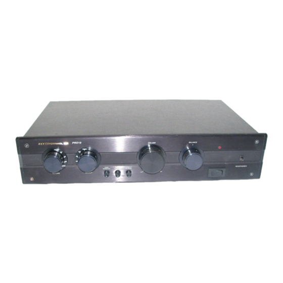
Page 5: Front Panel View
Front panel view Record selector knob Source selector knob Tape monitor button Direct bypass button Power switch (mute switch) Headphone jack Power on LED Balance knob Volume knob Mono/Stereo selector button Page 5... -
Page 6: Front Panel Description
Front panel description RECORD - Controls which one of the six input pairs is routed directly to the record output connectors (REC OUT). The selected input signal bypasses the remainder of the preamplifier’s circuitry to provide the purest possible recording source. SELECT - Controls which one of the six input pairs is routed to the processing circuitry and then to the preamplifier output connectors (PRE AMP OUT). -
Page 7: Balance
BALANCE - The balance control is used to adjust the relative volume of the left and right channels. This affects the PRE AMP OUT connections and the headphone output. VOLUME - Turning the volume control clockwise increases the volume level, counterclockwise decreases the volume level. -
Page 8: Back Panel View
Back panel view Balanced pre-outputs Unbalanced pre-outputs (RCA) Tape monitor loop Line level inputs Phono inputs Phono Ground connection Power connection for external power supply Page 8... -
Page 9: Back Panel Description
Back panel description BALANCED PREOUTS - For use with balanced output cables when your amplifier has balanced inputs. The balanced outputs will help improve the quality of sound being reproduced by the amplifier when there is a long run between the amplifier and the preamplifier. -
Page 10: Phono Ground
PHONO GROUND - For connection of your ground wire for phono use. POWER CONNECTION - For connection of the included power supply. ** Caution must be taken when connecting the included power supply. Do not force the plug as you may damage the pins inside the preamplifier. The plug is keyed so you can only insert it in one orientation. -
Page 11: Resistive Loading
selector switch. Trim the leads of the capacitors (one required per channel) to approximately inch. Insert the leads into the CLOAD pin receptacles securely. Resistive Loading NOTE: The PRO10 is shipped from the factory with a 100 Kohm resistor installed and the phono stage MM configuration selected. -
Page 12: Tables
NOTE: You may not be able to attain the proper value resistor to fit you application, use the closest standard value you can find. Refer to the following table for more calculated values of MM Rc desired Ri calculated Ri standard (ohms) (ohms) (ohms) -
Page 13: Block Diagram
Figure 1 Block Diagram Page 13... - Page 14 Page 14...
-
Page 15: Making The Connection
Making the connection The diagram below shows a typical connection between the preamplifier and a B&K amplifier using the unbalanced RCA outputs. Note: The balanced button on the amplifier must be in the off (out) position. The diagram below shows a typical connection between the preamplifier and a B&K amplifier using the balanced XLR outputs. - Page 16 Page 16...
-
Page 17: Specifications
PRO10 Specifications Moving Coil Sensitivity (at 1kHz) .09 mV Moving Coil Overload (at 1kHz) 17 mV Moving Coil Load Resistance Variable Moving Coil Load Capacitance Variable Moving Coil (S/N A Weighted) 70 dB Moving Magnet Sensitivity (at 1kHz) .8 mV Moving Magnet Overload (at 1kHz) 225 mV Moving Magnet Load Resistance... -
Page 18: Warranty
Limited Warranty B&K Components Ltd., referred to herein as B&K, warrants your B&K equipment against all defects in material and workmanship for a period of five years from the date of purchase. This warranty applies only to the original purchaser and only to equipment in normal residential use and service. Defective equipment must be returned to B&K, prepaid, accompanied by sufficient payment to cover the cost of return shipping and handling, and will be repaired or replaced at the discretion of B&K whose decision as to the method of reparation will be final.
Need help?
Do you have a question about the Pro10 and is the answer not in the manual?
Questions and answers