Table of Contents
Advertisement
Advertisement
Table of Contents

Summary of Contents for B&K Phono10
- Page 1 B&K IMPLY ETTER B&K Components, Ltd. Phono 10 Owner’s Manual P/N12839 0902...
- Page 2 B&K Components, Ltd., 2100 Old Union Road, Buffalo New York 14227-2725 Phone 1-800-543-5252 or (716) 656-0026, Fax (716) 656-1291 E-mail: info@bkcomp.com Web: www.bkcomp.com...
-
Page 3: Table Of Contents
TABLE OF CONTENTS Table of Contents...........................iii Safety Precautions ..........................1 Introduction .............................2 Features ..............................2 Rear Panel View ............................3 Design and Construction ........................4 Phono 10 Connections ...........................4 Phono Stage ............................5 Selecting Moving Magnet / Moving Coil ..........................5 Capacitive Loading .................................6 Resistive Loading..................................6 Control I/O Connections.........................8 Gain Switch .............................9 Digital Output ............................9... -
Page 4: Safety Precautions
SAFETY PRECAUTIONS PLEASE READ BEFORE INSTALLING WARNING: to prevent fire or shock hazard, do not expose this unit to rain or moisture. Care should be taken to prevent objects or liquid from entering the enclosure. Never handle the power cord with wet hands. -
Page 5: Introduction
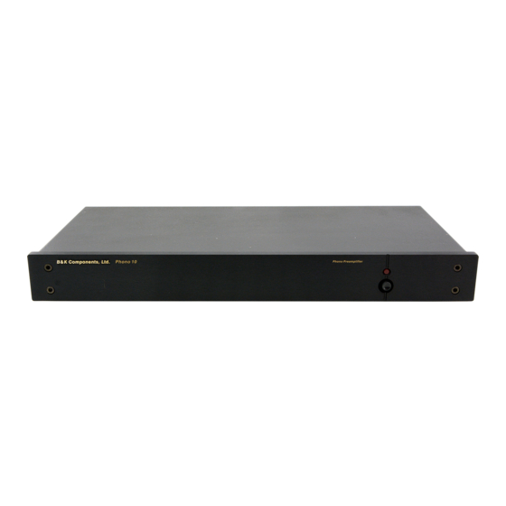
INTRODUCTION Thank you for selecting B&K Components, Ltd.’s Phono 10 phono preamplifier. The Phono 10 is a discrete circuit DC coupled topology RIAA phono preamplifier. It features a selectable head amp for use with both Moving Coil (MC) and Moving Magnet (MM) players. In addition to a control I/O circuit is incorporated for standby / turn-on from an external device there is also a S/PDIF coax digital output for use with CD quality recording. -
Page 6: Rear Panel View
REAR PANEL VIEW Gain Left and Right Left and Right Control I /O Analog Outputs Analog Inputs Switch B&K C O N T R O L C O N T R O L C A U T I O N I / O I / O D I G I TA L... -
Page 7: Design And Construction
DESIGN AND CONSTRUCTION The Phono 10 utilizes high quality electronic circuitry to achieve an environment wherein a detailed, transparent and highly musical sound can be realized. The high quality parts complement includes state-of-the-art solid state devices, 1% metal film resistors, polypropylene capacitors and a low noise toroidal transformer. PHONO 10 CONNECTIONS All leads should be connected securely to the input and output terminals. -
Page 8: Phono Stage
PHONO STAGE The phono stage of the Phono 10 may be configured for either Moving Magnet (MM) or Moving Coil (MC) applications with the additional capability to set the resistive and capacitive loading of the phono cartridge. Note: Your Phono 10 has already been configured for a MM stage with a resistive load of 50 Kohms. You do not have to perform any modifications unless you so desire. -
Page 9: Capacitive Loading
IMPORTANT - ENSURE THAT THE POWER CORD IS DISCONNECTED FROM THE AC OUTLET PRIOR TO PERFORMING ANY OF THE FOLLOWING PROCEDURES! CAPACITIVE LOADING NOTE: The Phono 10 is shipped from the factory with no capacitor installed. Typically, the capacitance of the phono cables (Cphono cables) is sufficient and no capacitor is needed. - Page 10 Table 1 Resistive Loading Rc desired Ri calculated Ri standard Examples (Ohms) (Ohms) (Ohms) 30.1 68.1 2.1 k 2.10 k 5.0 k 5.3 k 5.36 k 20.0 k 25.0 k 24.9 k 35.0 k 53.8 k 53.6 k 50.0 k 100.0 k * 100 k 75.0 k...
-
Page 11: Control I/O Connections
CONTROL I/O CONNECTIONS A control input/output is provided on the Phono 10 preamplifier to remotely turn the unit on and off. A receiver or preamplifiers control output, such as is provided with the B&K series, can be utilized to provide a control signal to the Phono 10. -
Page 12: Gain Switch
GAIN SWITCH A gain switch is provided on the Phono 10 to help match the Left and Right output level to that of the other sources in the system. This is useful in maintaining a constant volume level of the receiver or preamplifier when selecting different sources. -
Page 13: Troubleshooting
TROUBLESHOOTING PROBLEM POSSIBLE CAUSE POSSIBLE SOLUTION No sound 1. Power cord not plugged in 1. Reconnect power cord (‘On’ LED not 2. Power off at AC source 2. Check AC switch or fuse illuminated) 3. AC power inlet fuse blown or faulty 3. -
Page 14: Specifications
SPECIFICATIONS Moving Coil Sensitivity (at 1 kHz) .09 mV Moving Coil Overload (at 1 kHz) 17 mV Moving Coil Load Resistance Variable Moving Coil Capacitance Variable Moving Coil (S/N A Weighted) 78 dB Moving Magnet Sensitivity (at 1 kHz) .8 mV Moving Magnet Overload (at 1 kHz) 225 mV Moving Magnet Load Resistance... -
Page 15: Limited Warranty
LIMITED WARRANTY B & K Components Ltd., referred to herein as B & K, warrants your B & K equipment against all defects in material and workmanship for a period of five years from the date of purchase. This warranty applies only to the original purchaser and only to equipment in normal residential use and service. -
Page 16: Www.bkcomp.com
WWW.BKCOMP.COM B&K Components, Ltd. 2100 Old Union Road Buffalo, New York 14227 Phone: 716 – 656 - 0026...


Need help?
Do you have a question about the Phono10 and is the answer not in the manual?
Questions and answers