Chamberlain MH Owner's Manual
Industrial duty door operator
Hide thumbs
Also See for MH:
- User manual (12 pages) ,
- Quick start (2 pages) ,
- Installation manual (32 pages)
Table of Contents
Advertisement
Quick Links
Advertisement
Table of Contents

Subscribe to Our Youtube Channel
Related Manuals for Chamberlain MH


Summary of Contents for Chamberlain MH
- Page 1 F A C T O R Y S E T OWNER'S MANUAL C2 Wiring See page 8 for MODELS: other wiring configurations ✦ ✦ INDUSTRIAL DUTY DOOR OPERATOR NOT FOR RESIDENTIAL USE 2 YEAR WARRANTY 41B6 Serial # (located on electrical box cover) Installation Date Wiring Type...
-
Page 2: Specifications
Model MJ: Floor level disconnect for emergency #48 chain manual door operation. OUTPUT SHAFT SPEED:..80 RPM Model MH: Floor level chain hoist with electrical interlock for emergency manual door operation. DOOR SPEED: ......approx. 9" per sec. depending on door Model HMJ: Includes both floor level disconnect systems described above. -
Page 3: Important Safety Notes
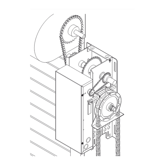
5-1/2" (13.97 cm) All MJ, MH, and HMJ series operators have dual output shafts and may be mounted on either the right (standard) or left side of door, and in either a vertical (standard) or horizontal mounting position. If you need to move the drive sprocket, loosen BOTH set screws, remove the sprocket and key, and place on the opposite side of the drive shaft. -
Page 4: Installation
INSTALLATION Important NOTE: Before your operator is installed, be sure the door has been properly aligned and is working smoothly. The operator may be wall mounted or mounted on a bracket or shelf. If necessary, refer to the operator preparations on page 3. Refer to the illustration and instructions below that suits your application. 1a. -
Page 5: Manual Operation
7. Install Hand Chain (Models MH and HMJ only) 8. Mount Chain Keeper / Keyhole Bracket Place hand chain around hand chain wheel. Be Using suitable hardware mount the chain keeper sure to pass it through both openings in the chain approximately 4 feet above the floor, near the free guide. -
Page 6: Entrapment Protection Accessories (Optional)
ENTRAPMENT PROTECTION ACCESSORIES (OPTIONAL) SENSING EDGES WARNING All types of sensing edges with an isolated normally open (N.O.) output are compatible with your operator. To reduce the risk of SEVERE INJURY or DEATH, ALWAYS This includes pneumatic and electric edges. If your install reversing sensors when the 3-button control station is CAUTION door does not have a bottom sensing edge and you... - Page 7 WARNING POWER WIRING WARNING POWER WIRING CONNECTIONS 1. Remove the cover from the electrical enclosure. To reduce the risk of SEVERE INJURY or DEATH: Inside this enclosure you will find the wiring diagram(s) • ANY maintenance to the operator or in the area near the for your unit.
-
Page 8: Special Control Wiring
CONTROL WIRING DETERMINE WIRING TYPE Refer to the wiring diagram located on the inside cover the electrical box to determine the type of control wiring. Standard C2 or B2 Wiring WARNING Standard operators are shipped from the factory with jumper set for C2 wiring, which requires constant To prevent possible SERIOUS INJURY or DEATH, install pressure on button to close the door. -
Page 9: Caution Warning
CONTROL WIRING (cont’d) WARNING WARNING WARNING Install the control station and receiver where the door is To prevent possible SERIOUS INJURY or DEATH from a moving visible, but away from the door and its hardware. When a gate or garage door: CAUTION CAUTION WARNING... -
Page 10: Test The System
WARNING WARNING TEST THE SYSTEM Turn on power. Test all controls and safety devices to CAUTION WARNING make sure they are working properly. It will be necessary to refer back to page 6 for fine adjustment To reduce the risk of SEVERE INJURY or DEATH: of the limit switches. -
Page 11: Maintenance Schedule
MAINTENANCE SCHEDULE Check at the intervals listed in the following chart. EVERY EVERY EVERY ITEM PROCEDURE 3 MONTHS 6 MONTHS 12 MONTHS Drive Chain Check for excessive slack. Check & adjust as required. ● ✔ Lubricate.* ● ✔ Sprockets Check set screw tightness ●... -
Page 12: Schematic Diagram
SCHEMATIC DIAGRAM 1754 (OPTIONAL) (OPTIONAL) BIMETAL LIGHT RELAY MAX. 100W CLOSE-B N.O. MOTOR * RES. OPEN-A CAPACITOR CLOSE-C BRAKE SOLENOID OPEN-C BL/BK WIRE NUT PR1. STOP (WHEN PRESENT) 10VA. 24VAC. HAND CHAIN SEC. INTERLOCK SW. MOVE JUMPER WIRE TO TERMINAL #2 FOR MOMENTARY CONTACT ON CLOSE CLOSE-A N.O. -
Page 13: Wiring Diagram
WIRING DIAGRAM 1754 OPEN CLOSE N.C. N.C. AUX.OPEN AUX.CLOSE N.C. N.O. RADIO REC'R TO REVERSE MOTOR DIRECTION INTERCHANGE RED & YELLOW WIRES. RESISTOR MOTOR BRAKE SOLENOID CAPACITOR BL/BK WIRE NUT BL/BK PRIMARY XFMR BL R SECONDARY BL/BK INTLK. N.O. OR P GROUND A.R.S. - Page 14 ELECTRICAL BOX - ILLUSTRATED PARTS...
- Page 15 REPLACEMENT PART KITS Below are replacement kits available for your operator. For replacement of electrical box, motor or brake components be sure to match model number of your unit to kit number below to ensure proper voltage requirements. Optional modifications and/or accessories included with your operator may add or remove certain components from these lists.
- Page 16 ILLUSTRATED PARTS – Model MJ...
- Page 17 Electrical Box - 86-RP04-100 Roll Pin 1/8x1" HMJ5025L, 230V LH K20-5150LD Motor - Model HMJ5011 K20-5250LD Motor - Model HMJ5025 K75-12588 · MH DISCONNECT SERVICE KIT ITEM PART# DESCRIPTION K72-12591 · CLUTCH SHAFT KIT 10-10707 Disconnect Support Bracket ITEM PART#...
- Page 18 ILLUSTRATED PARTS – Model MH...
- Page 19 REPLACEMENT PARTS LIST – MODEL SERVICE KITS INDIVIDUAL PARTS ITEM PART# DESCRIPTION ITEM PART# DESCRIPTION K72-19979 Clutch Shaft Kit 11-19471 Clutch Shaft - H 12-19504 Keyed Flange Bearing 1" Complete with: Clutch Shaft, Keyed Flange Bearing, Dual 15-19480 Dual Sprocket 32/14 Sprocket 32/14, 14 Tooth Sprocket, 15-19481 Sprocket, 14 Tooth...
- Page 20 ILLUSTRATED PARTS – Model HMJ...
- Page 21 REPLACEMENT PARTS LIST – MODEL SERVICE KITS INDIVIDUAL PARTS ITEM PART# DESCRIPTION ITEM PART# DESCRIPTION K72-19975 Clutch Shaft Kit 11-19470* Clutch Shaft - J Complete with: Clutch Shaft, 12-19504 Keyed Flange Bearing 1" 1" Keyed Flange Bearings, Dual 15-19480 Dual Sprocket 32/14 Sprocket 32/14, Splined Core 15-19484 Splined Core Sprocket...
-
Page 22: Operator Notes
OPERATOR NOTES... - Page 23 OPERATOR NOTES...
-
Page 24: Control Connection Diagram
CONTROL CONNECTION DIAGRAM IMPORTANT NOTES: wire device such as pullswitch, single button, loop detector, 1) The 3-Button Control Station provided must be connected for card key or such device. operation. 4) When adding accessories, install them one at a time and test 2) If a STOP button is not used, a jumper must be placed each one after it is added to ensure proper installation and between terminals 3 and 4.
Need help?
Do you have a question about the MH and is the answer not in the manual?
Questions and answers