Table of Contents
Advertisement
Advertisement
Table of Contents

Related Manuals for Asus F1A55-M/CSM


Summary of Contents for Asus F1A55-M/CSM
- Page 1 F1A55-M...
- Page 2 Product warranty or service will not be extended if: (1) the product is repaired, modified or altered, unless such repair, modification of alteration is authorized in writing by ASUS; or (2) the serial number of the product is defaced or missing.
-
Page 3: Table Of Contents
Contents Notices ......................vi Safety information ..................vii About this guide ..................viii F1A55-M specifications summary ............. ix Chapter 1: Product introduction Welcome! ..................1-1 Package contents ................. 1-1 Special features ................1-1 1.3.1 Product highlights ............1-1 Before you proceed ..............1-4 Motherboard overview .............. - Page 4 Managing and updating your BIOS ..........2-1 2.1.1 ASUS Update utility ............2-1 2.1.2 ASUS EZ Flash 2 ............2-2 2.1.3 ASUS CrashFree BIOS 3 utility ........2-3 2.1.4 ASUS BIOS Updater ............2-4 BIOS setup program ..............2-7 Main menu .................. 2-11 2.3.1 System Language [English] ...........2-11...
- Page 5 Setup Mode [EZ Mode] ..........2-26 2.7.6 Boot Option Priorities ............ 2-26 2.7.7 Boot Override ..............2-26 Tools menu ................. 2-27 2.8.1 ASUS EZ Flash 2 Utility ..........2-27 2.8.2 ASUS O.C. Profile ............2-27 2.8.3 ASUS SPD Information ..........2-27 Exit menu ..................2-28...
-
Page 6: Notices
This class B digital apparatus complies with Canadian ICES-003. ASUS Recycling/Takeback Services ASUS recycling and takeback programs come from our commitment to the highest standards for protecting our environment. We believe in providing solutions for you to be able to responsibly recycle our products, batteries, other components as well as the packaging materials. -
Page 7: Safety Information
Complying with the REACH (Registration, Evaluation, Authorisation, and Restriction of Chemicals) regulatory framework, we published the chemical substances in our products at ASUS REACH website at http://csr.asus.com/english/REACH.htm. DO NOT throw the motherboard in municipal waste. This product has been designed to enable proper reuse of parts and recycling. -
Page 8: About This Guide
Refer to the following sources for additional information and for product and software updates. ASUS websites The ASUS website provides updated information on ASUS hardware and software products. Refer to the ASUS contact information. Optional documentation Your product package may include optional documentation, such as warranty flyers, that may have been added by your dealer. -
Page 9: F1A55-M Specifications Summary
DDR3 1866 /1600/ 1333/ 1066 MHz memory modules The maximum 64GB memory capacity can be supported with 16GB or above DIMMs. ASUS will update the memory QVL once the DIMMs are available in the market. ** Refer to www.asus.com for the latest Memory QVL (Qualified Vendors List). - Page 10 ASUS unique features ASUS EPU TurboV MemOK! AI Suite II Anti-Surge Protection ASUS Fan Xpert ASUS UEFI BIOS EZ Mode featuring user-friendly graphics interface ASUS CrashFree BIOS 3 ASUS EZ Flash 2 ASUS MyLogo 2™ ASUS exclusive Precision Tweaker 2 overclocking features - vCore: Adjustable CPU voltage at 0.003125V increment...
- Page 11 1 x I/O shield 1 x User Manual 1 x Support DVD Support DVD Drivers ASUS utilities ASUS Update Anti-Virus software (OEM version) Form factor uATX form factor: 9.6 in x 9.6 in (24.4 cm x 24.4 cm) *Specifications are subject to change without notice.
-
Page 13: Chapter 1: Product Introduction
® The motherboard delivers a host of new features and latest technologies, making it another standout in the long line of ASUS quality motherboards! Before you start installing the motherboard, and hardware devices on it, check the items in your package with the list below. -
Page 14: Asus Exclusive Features
ASUS TurboV Feel the adrenaline rush of real-time OC-now a reality with the ASUS TurboV. This easy OC tool allows you to overclock without exiting or rebooting the OS; and its user-friendly interface makes overclock with just a few clicks away. -
Page 15: Asus Mylogo 2
ASUS EZ Flash 2 ASUS EZ Flash 2 is a user-friendly utility that allows you to update the BIOS without using a bootable floppy disk or an OS-based utility. ASUS MyLogo 2™... -
Page 16: Before You Proceed
ErP requires products to meet certain energy efficiency requirements in regards to energy consumptions. This is in line with ASUS vision of creating environment-friendly and energy-efficient products through product design and innovation to reduce carbon footprint of the product and thus mitigate environmental impacts. -
Page 17: Motherboard Overview
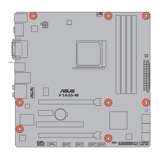
Screw holes Place eight screws into the holes indicated by circles to secure the motherboard to the chassis. DO NOT overtighten the screws! Doing so can damage the motherboard. Place this side towards the rear of the chassis. F1A55-M ASUS F1A55-M... -
Page 18: Motherboard Layout
1.5.3 Motherboard layout 24.4cm(9.6in) KB_USB3_E12 CPU_FAN SPDIF_O2 ATX12V 1042 _HDMI MemOK! DRAM_LED USB34 LAN1_USB12 AUDIO F1A55-M PCIEX16_1 8111E SB_PWR PCIEX1_1 Lithium Cell CMOS Power ® Super PCI1 PCIEX16_2 32Mb BIOS VT1708S SPDIF_OUT COM1 USB56 USB78 USB910 USB1112 CLRTC AAFP PANEL 1.5.4 Layout contents Connectors/Jumpers/Slots/LED... -
Page 19: Accelerated Processing Unit (Apu)
Carefully insert the APU into the socket until it fits in place. The APU fits only in one correct orientation. DO NOT force the APU into the socket to prevent bending the pins and damaging the APU! Small triangle Gold triangle ASUS F1A55-M... - Page 20 When the APU is in place, push down the socket lever to secure the APU. The lever clicks on the side tab to indicate that it is locked. Install a APU heatsink and fan following the instructions that comes with the heatsink package. You can also refer to section 1.6.2 Installing heatsink and fan for instructions.
-
Page 21: Installing The Heatsink And Fan
Your boxed CPU heatsink and fan assembly should come with installation instructions for the CPU, heatsink, and the retention mechanism. If the instructions in this section do not match the CPU documentation, follow the latter. Attach one end of the retention bracket to the retention module base. ASUS F1A55-M... -
Page 22: System Memory
Align the other end of the retention bracket to the retention module base. A clicking sound denotes that the retention bracket is in place. Ensure that the fan and heatsink assembly perfectly fits the retention mechanism module base, otherwise you cannot snap the retention bracket in place. Push down the retention bracket lock on the retention mechanism to secure the heatsink and fan to the module base. -
Page 23: Memory Configurations
• The maximum 64GB memory capacity can be supported with 16GB or above DIMMs. ASUS will update the memory QVL once the DIMMs are available in the market. • The default memory operation frequency is dependent on its Serial Presence Detect (SPD), which is the standard way of accessing information from a memory module. - Page 24 F1A55-M Motherboard Qualified Vendors Lists (QVL) DDR3-1866MHz capability DIMM socket support (Optional) Chip Vendors Part No. Size Brand Chip NO. Timing Voltage CORSAIR CMT4GX3M2A1866C9(XMP) 4GB(2 x 2GB) DS - 9-9-9-24 1.65V • • • CORSAIR CMZ8GX3M2A1866C9(XMP) 8GB(2 x 4GB) DS - 9-10-9-27 1.50V •...
- Page 25 4GB(2 x 2GB) DS - 7-7-7-20 1.75V • • OCZ3P1333LV6GK 6GB(3 x 2GB) DS - 7-7-7-20 1.65V • • • AL7F8G73F-DJ2 SS PSC A3P1GF3FGF • • • AL8F8G73F-DJ2 DS PSC A3P1GF3FGF • • • (continued on the next page) ASUS F1A55-M 1-13...
- Page 26 • C*: Supports two pairs of modules inserted into both the blue slots and the black slots as two pairs of dual-channel memory configuration. Visit the ASUS website at www.asus.com for the latest QVL. 1-14 Chapter 1: Product introduction...
-
Page 27: Installing A Dimm
DIMM. Support the DIMM lightly with your fingers when pressing the retaining clips. The DIMM might get damaged when it flips out with extra force. DIMM notch Remove the DIMM from the socket. ASUS F1A55-M 1-15... -
Page 28: Expansion Slots
Expansion slots In the future, you may need to install expansion cards. The following sub-sections describe the slots and the expansion cards that they support. Unplug the power cord before adding or removing expansion cards. Failure to do so may cause you physical injury and damage motherboard components. -
Page 29: Jumpers
• You do not need to clear the RTC when the system hangs due to overclocking. For system failure due to overclocking, use the CPU Parameter Recall (C.P.R) feature. Shut down and reboot the system so the BIOS can automatically reset parameter settings to default values. ASUS F1A55-M 1-17... -
Page 30: Connectors
1.10 Connectors 1.10.1 Rear panel ports 5 6 7 8 PS/2 Keyboard/Mouse Combo port (purple/green). This port is for a PS/2 keyboard or PS/2 mouse. Optical S/PDIF Out port. This port connects an external audio output device via an optical S/PDIF cable. Video Graphics Adapter (VGA) port. - Page 31 OS environment and after the USB 3.0 driver installation. • USB 3.0 devices can only be used as data storage only. • We strongly recommend that you connect USB 3.0 devices to USB 3.0 ports for faster and better performance for your USB 3.0 devices. ASUS F1A55-M 1-19...
-
Page 32: Internal Connectors
• The CPU_FAN connector supports a CPU fan of maximum 2A (24 W) fan power. • Only the CPU_FAN and CHA_FAN1 connectors support the ASUS Fan Xpert feature. • If you install two VGA cards, we recommend that you plug the rear chassis fan cable to the motherboard connector labeled CHA_FAN1 for better thermal environment. -
Page 33: Atx Power Connectors
The system may become unstable or may not boot up if the power is inadequate. • If you are uncertain about the minimum power supply requirement for your system, refer to the Recommended Power Supply Wattage Calculator at http://support.asus. com/PowerSupplyCalculator/PSCalculator.aspx?SLanguage=en-us for details. ASUS F1A55-M... - Page 34 Serial ATA 3.0 Gb/s connectors (7-pin SATA3G_1~6) These connectors are for the Serial ATA 3.0 Gb/s signal cables for Serial ATA hard disk drives and optical disc drives. If you installed Serial ATA hard disk drives, you can create a RAID 0, RAID 1, RAID 10, or JBOD configuration through the onboard controller.
-
Page 35: System Panel Connector
ATX power button/soft-off button (2-pin PWRSW) This connector is for the system power button. • Reset button (2-pin RESET) This 2-pin connector is for the chassis-mounted reset button for system reboot without turning off the system power. ASUS F1A55-M 1-23... -
Page 36: Front Panel Audio Connector
Digital audio connector (4-1 pin SPDIF_OUT) This connector is for an additional Sony/Philips Digital Interface (S/PDIF) port. F1A55-M SPDIF_OUT F1A55-M Digital audio connector Ensure that the audio device of Sound playback is VIA High Definition Audio (the name may be different based on the OS). Go to Start > Control Panel > Sounds and Audio Devices >... -
Page 37: Usb Connectors
USB78 USB910 USB1112 F1A55-M PIN 1 PIN 1 PIN 1 PIN 1 F1A55-M USB2.0 connectors Never connect a 1394 cable to the USB connectors. Doing so will damage the motherboard! The USB 2.0 module is purchased separately. ASUS F1A55-M 1-25... -
Page 38: Onboard Switches
If the installed DIMMs still fail to boot after the whole tuning process, the DRAM_LED lights continuously. Replace the DIMMs with ones recommended in the Memory QVL (Qualified Vendors Lists) in this user manual or on the ASUS website at www.asus.com. -
Page 39: Onboard Leds
, the LED next to the error device will continue lighting until the problem is solved. This user-friendly design provides an intuitional way to locate the root problem within a second. DRAM LED F1A55-M F1A55-M DRAM LED ASUS F1A55-M 1-27... -
Page 40: Software Support
The contents of the Support DVD are subject to change at any time without notice. Visit the ASUS website at www.asus.com for updates. To run the Support DVD Place the Support DVD into the optical drive. -
Page 41: Chapter 2: Bios Information
BIOS in the future. Copy the original motherboard BIOS using the ASUS Update utility. 2.1.1 ASUS Update utility The ASUS Update is a utility that allows you to manage, save, and update the motherboard BIOS in Windows environment. ®... -
Page 42: Asus Ez Flash 2
Follow the onscreen instructions to complete the updating process. 2.1.2 ASUS EZ Flash 2 The ASUS EZ Flash 2 feature allows you to update the BIOS without using an OS-based utility. Before you start using this utility, download the latest BIOS file from the ASUS website at www.asus.com. -
Page 43: Asus Crashfree Bios 3 Utility
2.1.3 ASUS CrashFree BIOS 3 utility The ASUS CrashFree BIOS 3 is an auto recovery tool that allows you to restore the BIOS file when it fails or gets corrupted during the updating process. You can restore a corrupted BIOS file using the motherboard support DVD or a USB flash drive that contains the updated BIOS file. -
Page 44: Asus Bios Updater
2.1.4 ASUS BIOS Updater The ASUS BIOS Updater allows you to update BIOS in DOS environment. This utility also allows you to copy the current BIOS file that you can use as a backup when the BIOS fails or gets corrupted during the updating process. - Page 45 Backing up the current BIOS To backup the current BIOS file using the BIOS Updater Ensure that the USB flash drive is not write-protected and has enough free space to save the file. At the FreeDOS prompt, type bupdater /o[filename] and press <Enter>. D:\>bupdater /oOLDBIOS1.rom Filename Extension The [filename] is any user-assigned filename with no more than eight alphanumeric...
-
Page 46: Updating The Bios File
• Ensure to load the BIOS default settings to ensure system compatibility and stability. Select the Load Optimized Defaults item under the Exit menu. Refer to section 2.9 Exit menu for details. • Ensure to connect all SATA hard disk drives after updating the BIOS file if you have disconnected them. ASUS F1A55-M... -
Page 47: Bios Setup Program
BIOS setup program Use the BIOS Setup program to update the BIOS or configure its parameters. The BIOS screens include navigation keys and brief online help to guide you in using the BIOS Setup program. Entering BIOS Setup at startup To enter BIOS Setup at startup: •... -
Page 48: Bios Menu Screen
Loads optimized default Selects the boot device priority Normal mode ASUS Optimal mode Displays the system properties of the selected mode on the right hand side The boot device options vary depending on the devices you installed to the system. -
Page 49: Advanced Mode
The Advanced Mode provides advanced options for experienced end-users to configure the BIOS settings. The figure below shows an example of the Advanced Mode. Refer to the following sections for the detailed configurations. To access the EZ Mode, click Exit, then select ASUS EZ Mode. Back button Menu items... -
Page 50: Menu Items
You cannot select an item that is not user-configurable. A configurable field is highlighted when selected. To change the value of a field, select it and press <Enter> or click on it to display a list of options. 2-10 ASUS F1A55-M... -
Page 51: Main Menu
Main menu The Main menu screen appears when you enter the Advanced Mode of the BIOS Setup program. The Main menu provides you an overview of the basic system information, and allows you to set the system date, time, language, and security settings. EFI BIOS Utility - Advanced Mode Exit Main... -
Page 52: Administrator Password
To clear the user password, follow the same steps as in changing a user password, but press <Enter> when prompted to create/confirm the password. After you clear the password, the User Password item on top of the screen shows Not Installed. 2-12 ASUS F1A55-M... -
Page 53: Ai Tweaker Menu
Ai Tweaker menu The Ai Tweaker menu items allow you to configure overclocking-related items. Be cautious when changing the settings of the Ai Tweaker menu items. Incorrect field values can cause the system to malfunction. The configuration options for this section vary depending on the CPU and DIMM model you installed on the motherboard. -
Page 54: Ai Overclock Tuner [Auto]
Saving Mode] [Medium Power Saving Mode] [Max Power Saving Mode] 2.4.5 OC Tuner OC Tuner automatically overclocks the frequency and voltage of CPU and DRAM for enhancing the system performance. Press <Enter> and select OK to start automatic overclocking. 2-14 ASUS F1A55-M... -
Page 55: Dram Timing Control
2.4.6 DRAM Timing Control The sub-items in this menu allow you to set the DRAM timing control features. Use the <+> and <-> keys to adjust the value. To restore the default setting, type [auto] using the keyboard and press <Enter>. Changing the values in this menu may cause the system to become unstable! If this happens, revert to the default settings. -
Page 56: Vdda Voltage [Auto]
This item allows you to set this function for better system performance. Configuration options: [Auto] [Disabled] [Enabled] The actual performance boost may vary depending on your CPU specification. 2.4.14 APU Spread Spectrum [Auto] [Auto] Automatic configuration. [Disabled] Enhances the PCIE overclocking ability. [Enabled] Sets to [Enabled] for EMI control. 2-16 ASUS F1A55-M... -
Page 57: Advanced Menu
Advanced menu The Advanced menu items allow you to change the settings for the CPU and other system devices. Be cautious when changing the settings of the Advanced menu items. Incorrect field values can cause the system to malfunction. EFI BIOS Utility - Advanced Mode Exit Main Ai Tweaker... -
Page 58: Sata Configuration
S.M.A.R.T. Status Check [Enabled] S.M.A.R.T. (Self-Monitoring, Analysis and Reporting Technology) is a monitor system. When read/write of your hard disk errors occur, this feature allows the hard disk to report warning messages during the POST. Configuration options: [Enabled] [Disabled] 2-18 ASUS F1A55-M... -
Page 59: Usb Configuration
2.5.3 USB Configuration The items in this menu allow you to change the USB-related features. The USB Devices item shows the auto-detected values. If no USB device is detected, the item shows None. Legacy USB Support [Enabled] [Enabled] Enables the support for USB devices on legacy operating systems (OS). [Disabled] The USB devices can be used only for the BIOS setup program. -
Page 60: Onboard Devices Configuration
Allows you to enable or disable the serial port (COM). Configuration options: [Enabled] [Disabled] Change Settings [Auto] Allows you to select the Serial Port base address. Configuration options: [Auto] [IO=3F8h; IRQ=4] [IO=2F8h; IRQ=3] [IO=3E8h; IRQ=4] [IO=2E8h; IRQ=3] 2-20 ASUS F1A55-M... -
Page 61: Apm
2.5.6 Restore AC Power Loss [Power Off] [Power On] The system goes into on state after an AC power loss. [Power Off] The system goes into off state after an AC power loss. [Last State] The system goes into either off or on state, whatever the system state was before the AC power loss. -
Page 62: Monitor Menu
The onboard hardware monitor automatically detects and displays the CPU / chassis / Power fan speeds in rotations per minute (RPM). If the fan is not connected to the motherboard, the field shows N/A. Select Ignore if you do not wish to display the detected speed. 2-22 ASUS F1A55-M... -
Page 63: Cpu Q-Fan Control [Enabled]
2.6.3 CPU Q-Fan Control [Enabled] [Disabled] Disables the CPU Q-Fan control feature. [Enabled] Enables the CPU Q-Fan control feature. CPU Fan Speed Low Limit [600 RPM] This item appears only when you enable the CPU Q-Fan Control feature and allows you to disable or set the CPU fan warning speed. -
Page 64: Cpu Voltage, 3.3V Voltage, 5V Voltage, 12V Voltage
The onboard hardware monitor automatically detects the voltage output through the onboard voltage regulators. Select Ignore if you do not want to detect this item. 2.6.6 Anti Surge Support [Disabled] This item allows you to enable or disable the Anti Surge function. Configuration options: [Disabled] [Enabled] 2-24 ASUS F1A55-M... -
Page 65: Boot Menu
[Disabled] Disables the full screen logo display feature. Set this item to [Enabled] to use the ASUS MyLogo 2™ feature. Post Report [5 sec] This item appears only when the Full Screen Logo item is set to [Disabled] and allows you to set the waiting time for the system to display the post report. -
Page 66: Option Rom Messages [Force Bios]
• To select the boot device during system startup, press <F8> when ASUS Logo appears. • To access Windows OS in Safe Mode, press <F8> after POST. -
Page 67: Tools Menu
> ASUS SPD Information 2.8.1 ASUS EZ Flash 2 Utility Allows you to run ASUS EZ Flash 2. Press [Enter] to launch the ASUS EZ Flash 2 screen. For more details, see section 2.1.2 ASUS EZ Flash 2. 2.8.2 ASUS O.C. Profile This item allows you to store or load multiple BIOS settings. -
Page 68: Exit Menu
Load Optimized Defaults Save Changes & Reset Discard Changes & Exit ASUS EZ Mode Launch EFI Shell from filesystem device Load Optimized Defaults This option allows you to load the default values for each of the parameters on the Setup menus. -
Page 69: Asus Contact Information
+1-510-739-3777 +1-510-608-4555 Web site usa.asus.com Technical Support Telephone +1-812-282-2787 Support fax +1-812-284-0883 Online support support.asus.com ASUS COMPUTER GmbH (Germany and Austria) Address Harkort Str. 21-23, D-40880 Ratingen, Germany +49-2102-959911 Web site www.asus.de Online contact www.asus.de/sales Technical Support Telephone (Component) +49-1805-010923*...
Need help?
Do you have a question about the F1A55-M/CSM and is the answer not in the manual?
Questions and answers