Table of Contents
Advertisement
Quick Links
Advertisement
Table of Contents

Related Manuals for Asus F1A55 R2.0


Summary of Contents for Asus F1A55 R2.0
- Page 1 F1A55 R2.0...
- Page 2 Product warranty or service will not be extended if: (1) the product is repaired, modified or altered, unless such repair, modification of alteration is authorized in writing by ASUS; or (2) the serial number of the product is defaced or missing.
-
Page 3: Table Of Contents
Contents Safety information ...................... vi About this guide ......................vii F1A55 R2.0 specifications summary ................ ix Package contents ...................... xii Product introduction Special features..................1-1 1.1.1 Product highlights................ 1-1 1.1.2 ASUS Exclusive features ............1-2 Before you proceed ................... 1-5 Motherboard overview ................ - Page 4 BIOS information 2-1 Managing and updating your BIOS ............2-1 2.1.1 ASUS Update utility..............2-1 2.1.2 ASUS EZ Flash 2 ................ 2-2 2.1.3 ASUS CrashFree BIOS 3 utility........... 2-3 2.1.4 ASUS BIOS Updater ..............2-4 BIOS setup program .................. 2-6 BIOS menu screen ..................
- Page 5 2.7.8 Boot Option Priorities ..............2-26 2.7.9 Boot Override ................2-26 Tools menu ....................2-27 2.8.1 ASUS EZ Flash 2 Utility ............2-27 2.8.2 ASUS O.C. Profile ..............2-27 2.8.3 ASUS SPD Information ............. 2-27 Exit menu ....................2-28 Appendices Notices ........................
-
Page 6: Safety Information
Safety information Electrical safety • To prevent electrical shock hazard, disconnect the power cable from the electrical outlet before relocating the system. • When adding or removing devices to or from the system, ensure that the power cables for the devices are unplugged before the signal cables are connected. If possible, disconnect all power cables from the existing system before you add a device. -
Page 7: About This Guide
Refer to the following sources for additional information and for product and software updates. ASUS websites The ASUS website provides updated information on ASUS hardware and software products. Refer to the ASUS contact information. Optional documentation Your product package may include optional documentation, such as warranty flyers, that may have been added by your dealer. -
Page 8: Conventions Used In This Guide
Conventions used in this guide To ensure that you perform certain tasks properly, take note of the following symbols used throughout this manual. DANGER/WARNING: Information to prevent injury to yourself when completing a task. CAUTION: Information to prevent damage to the components when completing a task IMPORTANT: Instructions that you MUST follow to complete a task. -
Page 9: F1A55 R2.0 Specifications Summary
Dual-channel memory architecture • The maximum 64GB memory capacity can be supported with 16GB or above DIMMs. ASUS will update the memory QVL once the DIMMs are available in the market. • Refer to www.asus.com for the latest Memory QVL (Qualified Vendors List). - Page 10 - ASUS UEFI BIOS EZ Mode - Hybrid DIGI+VRM - ASUS EPU - Network iControl ASUS Quiet Thermal Solution - ASUS Fanless Design: Stylish heatsink solution - ASUS Fan Xpert ASUS EZ DIY - ASUS CrashFree BIOS 3 - ASUS EZ Flash 2 - ASUS My Logo 2™...
- Page 11 F1A55 R2.0 specifications summary Internal I/O 3 x USB 2.0/1.1 connectors support additional 6 USB 2.0/1.1 ports connectors / buttons / 6 x SATA 3.0Gb/s connectors switches 1 x COM connector 1 x CPU fan connector 2 x Chassis fan connectors...
-
Page 12: Package Contents
DDR3 DIMM_B2 (64bit, 240-pin module) SATA3G_1 SATA3G_3 SATA3G_5 SATA3G_2 SATA3G_4 SATA3G_6 ASUS F1A55 R2.0 motherboard 2 x Serial ATA 3.0 Gb/s cables 1 x I/O-Shield User Guide Support DVD • If any of the above items is damaged or missing, contact your retailer. -
Page 13: Product Introduction
USB 3.0 transfers data 10x faster and is also backward compatible with USB 2.0 components. 100% All High-quality Conductive Polymer Capacitors This motherboard uses all high-quality conductive polymer capacitors for durability, improved lifespan, and enhanced thermal capacity. ASUS F1A55 R2.0... -
Page 14: Asus Exclusive Features
Based on technology developed for high performance ASUS products, Hybrid DIGI+ VRM on ASUS motherboards with the AMD A55 chipset allows APU voltage and VRM frequency adjustments via smart preset modes and user-defined profiles. -
Page 15: Asus Turbov
*** The actual charging speed may vary with your USB device’s conditions. ASUS TurboV Feel the adrenaline rush of real-time OC — now a reality with the ASUS TurboV. This easy OC tool allows you to overclock without exiting or rebooting the OS;... - Page 16 ErP requires products to meet certain energy efficiency requirements with regard to energy consumption. This is in line with ASUS’ vision of creating environment-friendly and energy-efficient products through product design and innovation to reduce carbon footprint of the product and thus mitigate environmental impact.
-
Page 17: Before You Proceed
Failure to do so can cause you physical injury and damage motherboard components. 1.3.1 Placement direction When installing the motherboard, place it into the chassis in the correct orientation. The edge with external ports goes to the rear part of the chassis as indicated in the image. ASUS F1A55 R2.0... -
Page 18: Screw Holes
Place six screws into the holes indicated by circles to secure the motherboard to the chassis. Do not overtighten the screws! Doing so can damage the motherboard. Place this side towards the rear of the chassis F1A55 R2.0 Chapter 1: Product introduction... -
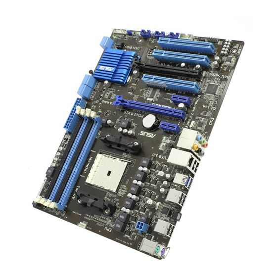
Page 19: Motherboard Layout
LAN1_USB12 CHA_FAN1 AUDIO PWR_FAN PCIEX1_1 Lithium Cell CMOS Power EATXPWR Realtek ® 8111E PCIEX16_1 F1A55 R2.0 PCIEX1_2 PCI1 Super ® A55 FCH PCIEX16_2 PCI2 64Mb BIOS PCI3 SB_PWR COM1 USB1112 USB910 USB78 CHA_FAN2 PANEL CLRTC SPDIF_OUT AAFP ASUS F1A55 R2.0... -
Page 20: Layout Contents
1.3.4 Layout contents Connectors/Jumpers/Slots/LED Page 1. Power, CPU and chassis fan connectors (3-pin PWR_FAN, 4-pin CPU_FAN, 1-23 and 4-pin CHA_FAN1/2) 2. ATX power connectors (24-pin EATXPWR, 4-pin ATX12V) 1-24 3. AMD FM1 socket 4. DDR3 DIMM slots 1-12 5. MemOK! switch 1-29 6. -
Page 21: Accelerated Processing Unit (Apu)
Contact your retailer immediately if the PnP cap is missing, or if you see any damage to the PnP cap/socket contacts/motherboard components. ASUS will shoulder the cost of repair only if the damage is shipment/ transit-related. - Page 22 Connect the CPU fan cable to the CPU_FAN connector on the motherboard. CPU_FAN F1A55 R2.0 F1A55 R2.0 CPU fan connector DO NOT forget to connect the CPU fan connector! Hardware monitoring errors can occur if you fail to plug this connector.
-
Page 23: Installing The Heatsink And Fan
Retention bracket lock Your boxed CPU heatsink and fan assembly should come with installation instructions for the CPU, heatsink, and the retention mechanism. If the instructions in this section do not match the CPU documentation, follow the latter. ASUS F1A55 R2.0 1-11... - Page 24 Attach one end of the retention bracket to the retention module base. Align the other end of the retention bracket to the retention module base. A clicking sound denotes that the retention bracket is in place. Ensure that the fan and heatsink assembly perfectly fits the retention mechanism module base, otherwise you cannot snap the retention bracket in place.
-
Page 25: System Memory
Sockets Channel A DIMM_A1 and DIMM_A2 Channel B DIMM_B1 and DIMM_B2 F1A55 R2.0 F1A55 R2.0 240-pin DDR3 DIMM sockets 1.5.2 Memory configurations You may install 1GB, 2GB, and 4GB unbuffered non-ECC DDR3 DIMMs into the DIMM sockets. • You may install varying memory sizes in Channel A and Channel B. The system maps the total size of the lower-sized channel for the dual-channel configuration. - Page 26 CPU’s capabilities and other installed devices. • The maximum 64GB memory capacity can be supported with 16GB or above DIMMs. ASUS will update the memory QVL once the DIMMs are available in the market. • The default memory operation frequency is dependent on its Serial Presence Detect (SPD), which is the standard way of accessing information from a memory module.
- Page 27 4GB(2 x 2GB) 8-8-8-24 1.7V • • • OCZ3OB1600LV4GK 4GB(2 x 2GB) 1.65V • • • OCZ3G1600LV6GK 6GB(3 x 2GB) 8-8-8-24 1.65V • • Super WA160UX6G9 6GB(3 x 2GB) • • • Talent (continued on the next page) ASUS F1A55 R2.0 1-15...
- Page 28 DDR3 1333 MHz capability DIMM socket support Chip (Optional) Vendors Part No. Size Chip NO. Timing Voltage Brand 1 DIMM 2 DIMMs 4 DIMMs A-Data AD63I1B0823EV SS A-Data 3CCA-1509A • • • 1.25V- A-Data AXDU1333GC2G9-2G(XMP) 4GB(2 x 2GB) SS - 9-9-9-24 1.35V(low •...
- Page 29 • C*: Supports two pairs of modules inserted into both the blue slots and the black slots as two pairs of dual-channel memory configuration. Visit the ASUS website at www.asus.com for the latest QVL. ASUS F1A55 R2.0 1-17...
-
Page 30: Installing A Dimm
1.5.3 Installing a DIMM Unplug the power supply before adding or removing DIMMs or other system components. Failure to do so can cause severe damage to both the motherboard and the components. Press the retaining clips outward to unlock a DIMM socket. DIMM notch Align a DIMM on the socket such that the notch on the DIMM matches the... -
Page 31: Expansion Slots
The PCI slots support cards such as a LAN card, SCSI card, USB card, and other cards that comply with PCI specifications. 1.6.4 PCI Express x1 slots This motherboard supports PCI Express x1 network cards, SCSI cards, and other cards that comply with the PCI Express specifications. ASUS F1A55 R2.0 1-19... -
Page 32: Pci Express X16 Slots
1.6.5 PCI Express x16 slots This motherboard supports two PCI Express x16 graphics cards that comply with the PCI Express specifications. PCI Express operating mode VGA configuration PCIe x16_1 PCIe x16_2 Single VGA/PCIe card (Recommended for single VGA card) Dual VGA/PCIe card •... -
Page 33: Jumpers
Normal Clear RTC (Default) F1A55 R2.0 Clear RTC RAM To erase the RTC RAM: Turn OFF the computer and unplug the power cord. Move the jumper cap from pins 1-2 (default) to pins 2-3. Keep the cap on pins 2-3 for about 5-10 seconds, then move the cap back to pins 1-2. -
Page 34: Connectors
Except when clearing the RTC RAM, never remove the cap on CLRTC jumper default position. Removing the cap will cause system boot failure! • If the steps above do not help, remove the onboard battery and move the jumper again to clear the CMOS RTC RAM data. After clearing the CMOS, reinstall the battery. - Page 35 ® • USB 3.0 devices can only be used for data storage. • We strongly recommend that you connect USB 3.0 devices to USB 3.0 ports for faster and better performance for your USB 3.0 devices. ASUS F1A55 R2.0 1-23...
-
Page 36: Internal Connectors
• The CPU_FAN connector supports a CPU fan of maximum 2A (24 W) fan power. • Only the CPU_FAN and CHA_FAN1/2 connectors support the ASUS Fan Xpert feature. • If you install two VGA cards, we recommend that you plug the rear chassis fan cable to the motherboard connector labeled CHA_FAN1/2 for better thermal environment. - Page 37 The system may become unstable or may not boot up if the power is inadequate. • If you are uncertain about the minimum power supply requirement for your system, refer to the Recommended Power Supply Wattage Calculator at http://support.asus. com/PowerSupplyCalculator/PSCalculator.aspx?SLanguage=en-us for details. ASUS F1A55 R2.0 1-25...
- Page 38 SATA3G_1 SATA3G_2 F1A55 R2.0 F1A55 R2.0 SATA 3.0Gb/s connectors These connectors are set to IDE mode by default. In IDE mode, you can connect • Serial ATA boot/data hard disk drives to these connectors. If you intend to create a Serial ATA RAID set using these connectors, set the type of the SATA connectors in the BIOS to [RAID].
- Page 39 COM1 PIN 1 F1A55 R2.0 F1A55 R2.0 Serial port (COM1) connector The COM module is purchased separately. Digital audio connector (4-1 pin SPDIF_OUT) This connector is for an additional Sony/Philips Digital Interface (S/PDIF) port.
-
Page 40: System Panel Connector
IDE_LED PWRSW RESET * Requires an ATX power supply F1A55 R2.0 System panel connector • System power LED (2-pin PLED) This 2-pin connector is for the system power LED. Connect the chassis power LED cable to this connector. The system power LED lights up when you turn on the system power, and blinks when the system is in sleep mode. - Page 41 F1A55 R2.0 HD-audio-compliant Legacy AC’97 pin definition compliant definition F1A55 R2.0 Front panel audio connector • We recommend that you connect a high-definition front panel audio module to this connector to avail of the motherboard high-definition audio capability. • If you want to connect a high definition front panel audio module to this connector, set the Front Panel Type item in the BIOS to [HD].
-
Page 42: Onboard Switch
BIOS default settings. A message will appear during POST reminding you that the BIOS has been restored to its default settings. • We recommend that you download and update to the latest BIOS version from the ASUS website at www.asus.com after using the MemOK! function. Chapter 1: Product introduction 1-30... -
Page 43: Onboard Leds
F1A55 R2.0 Standby Power Powered Off F1A55 R2.0 Onboard LED DRAM LED The DRAM LED checks the DRAM in sequence during the motherboard boot process. If an error is found, the LED next to the error device will light up until the problem is solved. -
Page 44: Software Support
Place the Support DVD into the optical drive. If Autorun is enabled in your computer, the DVD automatically displays the Specials screen which contains the unique features of ASUS motherboard. Click Drivers, Utilities, Make Disk, Manual, and Contact tabs to display their respective menus. -
Page 45: Bios Information
BIOS in the future. Copy the original motherboard BIOS using the ASUS Update utility. 2.1.1 ASUS Update utility The ASUS Update is a utility that allows you to manage, save, and update the motherboard BIOS in Windows environment. ®... -
Page 46: Asus Ez Flash 2
Follow the onscreen instructions to complete the updating process. 2.1.2 ASUS EZ Flash 2 The ASUS EZ Flash 2 feature allows you to update the BIOS without using an OS-based utility. Before you start using this utility, download the latest BIOS file from the ASUS website at www.asus.com. -
Page 47: Asus Crashfree Bios 3 Utility
2.1.3 ASUS CrashFree BIOS 3 utility The ASUS CrashFree BIOS 3 is an auto recovery tool that allows you to restore the BIOS file when it fails or gets corrupted during the updating process. You can restore a corrupted BIOS file using the motherboard support DVD or a USB flash drive that contains the updated BIOS file. -
Page 48: Asus Bios Updater
2.1.4 ASUS BIOS Updater The ASUS BIOS Updater allows you to update BIOS in a DOS environment. This utility also allows you to copy the current BIOS file that you can use as a backup when the BIOS fails or gets corrupted during the updating process. -
Page 49: Updating The Bios File
Select the Load Optimized Defaults item under the Exit menu. Refer to section 2.9 Exit menu for details. • Ensure to connect all SATA hard disk drives after updating the BIOS file if you have disconnected them. ASUS F1A55 R2.0... -
Page 50: Bios Setup Program
The BIOS setup screens shown in this section are for reference purposes only, and may not exactly match what you see on your screen. Visit the ASUS website at www.asus.com to download the latest BIOS file for this • motherboard. -
Page 51: Bios Menu Screen
Selects the boot Turbo mode device priority • The boot device options vary depending on the devices you installed to the system. The Boot Menu(F8) button is available only when the boot device is installed to the • system. ASUS F1A55 R2.0... -
Page 52: Advanced Mode
The Advanced Mode provides advanced options for experienced end-users to configure the BIOS settings. The figure below shows an example of the Advanced Mode. Refer to the following sections for the detailed configurations. To access the EZ Mode, click Exit, then select ASUS EZ Mode. Back button Menu items... -
Page 53: Menu Items
You cannot select an item that is not user-configurable. A configurable field is highlighted when selected. To change the value of a field, select it and press <Enter> to display a list of options. ASUS F1A55 R2.0... -
Page 54: Main Menu
Main menu The Main menu screen appears when you enter the Advanced Mode of the BIOS Setup program. The Main menu provides you an overview of the basic system information, and allows you to set the system date, time, language, and security settings. 2.3.1 System Language [English] Allows you to choose the BIOS language version from the options. -
Page 55: Administrator Password
To clear the user password, follow the same steps as in changing a user password, but press <Enter> when prompted to create/confirm the password. After you clear the password, the User Password item on top of the screen shows Not Installed. ASUS F1A55 R2.0 2-11... -
Page 56: Ai Tweaker Menu
Ai Tweaker menu The Ai Tweaker menu items allow you to configure overclocking-related items. Be cautious when changing the settings of the Ai Tweaker menu items. Incorrect field values can cause the system to malfunction. The configuration options for this section vary depending on the CPU and DIMM model you installed on the motherboard. -
Page 57: Ai Overclock Tuner [Auto]
Interface). Use the <+> and <-> keys to adjust the ratio. The valid value ranges vary according to your CPU model. 2.4.4 EPU Power Saving Mode [Disabled] Allows you to enable or disable the EPU power saving function. Configuration options: [Disabled] [Enabled] ASUS F1A55 R2.0 2-13... -
Page 58: Oc Tuner [Ok]
EPU Setting [Auto] This item appears only when you set the EPU Power Saving Mode item to [Enabled] and allows you to select the EPU power saving mode. Configuration options: [Auto] [Light Power Saving Mode] [Medium Power Saving Mode] [Max Power Saving Mode] 2.4.5 OC Tuner [OK] OC Tuner automatically overclocks the frequency and voltage of CPU and DRAM for... -
Page 59: Cpu Voltage [Offset Mode]
Allows you to set the 1.1Vsb voltage. The values range from 1.1000V to 1.2000V with a 0.1V interval. 2.4.14 APU 1.2V Voltage [Auto] Allows you to set the APU (Accelerated Processor Unit) 1.2V voltage. The values range from 1.2000V to 1.8000V with a 0.01V interval. ASUS F1A55 R2.0 2-15... -
Page 60: Vdda Voltage [Auto]
2.4.15 VDDA Voltage [Auto] Allows you to set the VDDA voltage. The values range from 2.5000V to 2.8000V with a 0.01V interval. • The values of the CPU Offset Voltage, VDDNB Offset Voltage, DRAM Voltage, SB 1.1V Voltage, 1.1Vsb Voltage, APU1.2V Voltage, and VDDA Voltage items are labeled in different color, indicating the risk levels of high voltage settings. -
Page 61: Cpu Configuration
While entering Setup, the BIOS automatically detects the presence of SATA devices. The SATA Port items show Not Present if no SATA device is installed to the corresponding SATA port. OnChip SATA Channel [Enabled] Enables or disables onboard channel SATA port. Configuration options: [Disable link] [Enabled] ASUS F1A55 R2.0 2-17... -
Page 62: Usb Configuration
OnChip SATA Type [IDE] Allows you to set the SATA configuration. [IDE] Set to [IDE] when you want to use the Serial ATA hard disk drives as Parallel ATA physical storage devices. [RAID] Set to [RAID] when you want to create a RAID configuration from the SATA hard disk drives. -
Page 63: Nb Configuration
Sets the front panel audio connector (AAFP) mode to high definition audio. [AC97] Sets the front panel audio connector (AAFP) mode to legacy AC’97 SPDIF Out Type [SPDIF] [SPDIF] Sets to [SPDIF] for SPDIF audio output. [HDMI] Sets to [HDMI] for HDMI audio output. ASUS F1A55 R2.0 2-19... -
Page 64: Apm
Realtek LAN Controller [Enabled] [Enabled] Enables the Realtek LAN controller. [Disabled] Disables the controller. Realtek PXE OPROM [Disabled] This item appears only when you set the previous item to [Enabled] and allows you to enable or disable the PXE OptionRom of the Realtek LAN controller. Configuration options: [Enabled] [Disabled] Asmedia USB 3.0 Controller [Enabled] [Enabled]... -
Page 65: Network Stack
This item allows user to disable or enable the Ipv4 PXE Boot support. Configuration options: [Disable Link] [Enable] Ipv6 PXE Support [Enabled] This item allows user to disable or enable the Ipv6 PXE Boot support. Configuration options: [Disable Link] [Enable] ASUS F1A55 R2.0 2-21... -
Page 66: Monitor Menu
Monitor menu The Monitor menu displays the system temperature/power status, and allows you to change the fan settings. Scroll down to display the following items: 2.6.1 CPU Temperature / MB Temperature [xxxºC/xxxºF] The onboard hardware monitor automatically detects and displays the CPU and motherboard temperatures. -
Page 67: Cpu Q-Fan Control [Enabled]
40% to 100%. When the CPU temperature is under the lower limit, the CPU fan will operate at the minimum duty cycle. 2.6.4 Chassis Q-Fan Control [Enabled] [Disabled] Disables the Chassis Q-Fan control feature. [Enabled] Enables the Chassis Q-Fan control feature. ASUS F1A55 R2.0 2-23... -
Page 68: Cpu Voltage, 5V Voltage, 12V Voltage
Chassis Fan Speed Low Limit [600 RPM] This item appears only when you enable the Chassis Q-Fan Control feature and allows you to disable or set the chassis fan warning speed. Configuration options: [Ignore] [200RPM] [300 RPM] [400 RPM] [500 RPM] [600 RPM] Chassis Fan Profile [Standard] This item appears only when you enable the Chassis Q-Fan Control feature and allows you to set the appropriate performance level of the chassis fan. -
Page 69: Boot Menu
[Disabled] Disables the full screen logo display feature. Set this item to [Enabled] to use the ASUS MyLogo 2™ feature. Post Report [5 sec] This item appears only when the Full Screen Logo item is set to [Disabled] and allows you to set the waiting time for the system to display the post report. -
Page 70: Wait For 'F1' If Error [Enabled]
• To select the boot device during system startup, press <F8> when ASUS Logo appears. • To access Windows OS in Safe Mode, do any of the following: •... -
Page 71: Tools Menu
<Enter> to display the submenu. 2.8.1 ASUS EZ Flash 2 Utility Allows you to run ASUS EZ Flash 2. Press [Enter] to launch the ASUS EZ Flash 2 screen. For more details, see section 2.1.2 ASUS EZ Flash 2. 2.8.2 ASUS O.C. -
Page 72: Exit Menu
This option allows you to exit the Setup program without saving your changes. When you select this option or if you press <Esc>, a confirmation window appears. Select Yes to discard changes and exit. ASUS EZ Mode This option allows you to enter the EZ Mode screen. Launch EFI Shell from filesystem device This option allows you to attempt to launch the EFI Shell application (shellx64.efi) from one of... -
Page 73: Appendices
Cet appareil est conforme aux normes CNR exemptes de licence d’Industrie Canada. Le fonctionnement est soumis aux deux conditions suivantes : (1) cet appareil ne doit pas provoquer d’interférences et (2) cet appareil doit accepter toute interférence, y compris celles susceptibles de provoquer un fonctionnement non souhaité de l’appareil. F1A55 R2.0... -
Page 74: Canadian Department Of Communications Statement
ASUS Recycling/Takeback Services ASUS recycling and takeback programs come from our commitment to the highest standards for protecting our environment. We believe in providing solutions for you to be able to responsibly recycle our products, batteries, other components as well as the packaging materials. -
Page 75: Asus Contact Information
+1-812-282-3777 +1-510-608-4555 Web site usa.asus.com Technical Support Telephone +1-812-282-2787 Support fax +1-812-284-0883 Online support support.asus.com ASUS COMPUTER GmbH (Germany and Austria) Address Harkort Str. 21-23, D-40880 Ratingen, Germany +49-2102-959911 Web site www.asus.de Online contact www.asus.de/sales Technical Support Telephone +49-1805-010923* Support Fax... - Page 76 Appendices...
Need help?
Do you have a question about the F1A55 R2.0 and is the answer not in the manual?
Questions and answers