Table of Contents
Advertisement
Advertisement
Table of Contents

Related Manuals for Asus F1A55-M LK R2.0


Summary of Contents for Asus F1A55-M LK R2.0
- Page 1 F1A55-M LK R2.0...
- Page 2 Product warranty or service will not be extended if: (1) the product is repaired, modified or altered, unless such repair, modification of alteration is authorized in writing by ASUS; or (2) the serial number of the product is defaced or missing.
-
Page 3: Table Of Contents
Contents Safety information ..................vi About this guide ..................vi F1A55-M LK R2.0 specifications summary ..........viii Chapter 1: Product introduction Welcome! ..................1-1 Package contents ................. 1-1 Special features ................1-1 1.3.1 Product highlights ............1-1 1.3.2 ASUS DIGI+ VRM ............1-2 1.3.3... - Page 4 Managing and updating your BIOS ..........2-1 2.1.1 ASUS Update utility ............2-1 2.1.2 ASUS EZ Flash 2 ............2-2 2.1.3 ASUS CrashFree BIOS 3 utility ........2-3 2.1.4 ASUS BIOS Updater ............2-4 BIOS setup program ..............2-6 Main menu .................. 2-10 2.3.1 System Language [English] ..........
- Page 5 2.7.8 Boot Option Priorities ............ 2-23 2.7.9 Boot Override ..............2-23 Tools menu ................. 2-24 2.8.1 ASUS EZ Flash 2 Utility ..........2-24 2.8.2 ASUS O.C. Profile ............2-24 2.8.3 ASUS SPD Information ..........2-24 Exit menu ..................2-25 Appendices...
-
Page 6: Safety Information
Safety information Electrical safety • To prevent electric shock hazard, disconnect the power cable from the electric outlet before relocating the system. • When adding or removing devices to or from the system, ensure that the power cables for the devices are unplugged before the signal cables are connected. If possible, disconnect all power cables from the existing system before you add a device. -
Page 7: Conventions Used In This Guide
Refer to the following sources for additional information and for product and software updates. ASUS websites The ASUS website provides updated information on ASUS hardware and software products. Refer to the ASUS contact information. Optional documentation Your product package may include optional documentation, such as warranty flyers, that may have been added by your dealer. -
Page 8: F1A55-M Lk R2.0 Specifications Summary
Dual-channel memory architecture * The maximum 32GB memory capacity can be supported with 16GB or above DIMMs. ASUS will update the memory QVL once the DIMMs are available in the market. ** Refer to www.asus.com for the latest Memory QVL (Qualified Vendors List). - Page 9 Network iControl* featuring instant network bandwidth domination for top network program in use ASUS EPU ASUS AI Suite II Anti-Surge Protection ASUS UEFI BIOS EZ Mode featuring friendly graphics user interface ASUS Fan Xpert ASUS CrashFree BIOS 3 ASUS EZ Flash 2 ASUS MyLogo 2™...
-
Page 11: Chapter 1: Product Introduction
® The motherboard delivers a host of new features and latest technologies, making it another standout in the long line of ASUS quality motherboards! Before you start installing the motherboard, and hardware devices on it, check the items in your package with the list below. -
Page 12: Asus Digi+ Vrm
The effect is that DIGI+ VRM technology ensures greater energy efficiency and the most precise power delivery. Boosted by world-renowned ASUS quality, it creates an ideal computing platform for a diverse range of applications, from gaming to multimedia or office work and heavy multitasking. -
Page 13: Asus Exclusive Features
- F12 BIOS snapshot hotkey for sharing UEFI information and troubleshooting - New F3 Shortcut for most accessed information - ASUS DRAM SPD (Serial Presence Detect) information for accessing memory information, detecting faulty DIMMs, and helping with difficult POST situations. -
Page 14: Fan Xpert
BIOS file using the bundled support DVD or USB flash disk that contains the latest BIOS file. ASUS EZ Flash 2 ASUS EZ Flash 2 is a utility that allows you to update the BIOS without using an OS-based utility. C.P.R. (CPU Parameter Recall) The BIOS C.P.R. -
Page 15: Before You Proceed
The illustration below shows the location of the onboard LED. SB_PWR F1A55-M LK R2.0 Standby Power Powered Off F1A55-M LK R2.0 Onboard LED ASUS F1A55-M LK R2.0... -
Page 16: Motherboard Overview
Place six screws into the holes indicated by circles to secure the motherboard to the chassis. DO NOT overtighten the screws! Doing so can damage the motherboard. Place this side towards the rear of the chassis. F1A55-M LK R2.0 Chapter 1: Product introduction... -
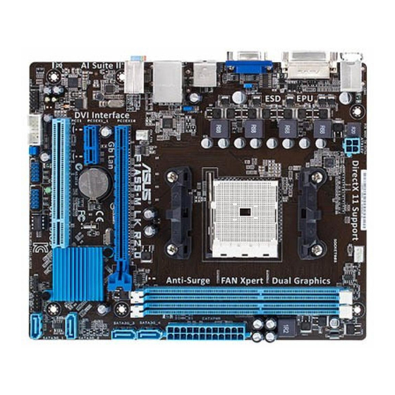
Page 17: Motherboard Layout
AMD FM1 socket 12. Clear RTC RAM (3-pin CLRTC) 1-18 DDR3 DIMM slots 1-11 13. Serial port connector (10-1 pin COM1) 1-25 SATA 3.0Gb/s connectors (7-pin SATA3G_1~4) 1-23 14. Front panel audio connector (10-1 pin AAFP) 1-25 ASUS F1A55-M LK R2.0... -
Page 18: Accelerated Processing Unit (Apu)
Installing the APU To install a APU: Locate the FM1 socket on the motherboard. F1A55-M LK R2.0 F1A55-M LK R2.0 CPU socket FM1 Socket lever Press the lever sideways to unlock the socket, then lift it up to a 90°-100° angle. - Page 19 Connect the CPU fan cable to the CPU_FAN connector on the motherboard. CPU_FAN F1A55-M LK R2.0 F1A55-M LK R2.0 CPU fan connector DO NOT forget to connect the CPU fan connector! Hardware monitoring errors can occur if you fail to plug this connector.
-
Page 20: Installing The Heatsink And Fan
1.6.2 Installing the heatsink and fan Ensure that you use only AMD-certified heatsink and fan assembly. To install the CPU heatsink and fan: Place the heatsink on top of the installed CPU, ensuring that the heatsink fits properly on the retention module base. •... -
Page 21: System Memory
The figure illustrates the location of the DDR3 DIMM sockets: Channel Sockets Channel A DIMM_A1 Channel B DIMM_B1 F1A55-M LK R2.0 F1A55-M LK R2.0 240-pin DDR3 DIMM sockets ASUS F1A55-M LK R2.0 1-11... -
Page 22: Memory Configurations
• The maximum 32GB memory capacity can be supported with 16GB or above DIMMs. ASUS will update the memory QVL once the DIMMs are available in the market. • The default memory operation frequency is dependent on its Serial Presence Detect (SPD), which is the standard way of accessing information from a memory module. - Page 23 CORSAIR CMD8GX3M4A1333C7 8GB(4 x 2GB) 7-7-7-20 1.60V • Crucial CT12864BA1339.8FF Micron 9FF22D9KPT • • Crucial CT25664BA1339.16FF Micron 9KF27D9KPT • • Crucial BL25664BN1337.16FF (XMP) 6GB(3 x 2GB) 7-7-7-24 1.65V • • (continued on the next page) ASUS F1A55-M LK R2.0 1-13...
- Page 24 DDR3-1333 MHz capability DIMM socket support Vendors Part No. Size Chip Brand Chip No. Timing Voltage (Optional) 1.35V(low ELPIDA EBJ10UE8EDF0-DJ-F ELPIDA J1108EDSE-DJ-F • • voltage) 1.35V(low ELPIDA EBJ21UE8EDF0-DJ-F ELPIDA J1108EDSE-DJ-F • • voltage) G.SKILL F3-10600CL8D-2GBHK (XMP) G.SKILL • • G.SKILL F3-10600CL9D-2GBNQ 2GB(2 x 1GB) 9-9-9-24 1.5V...
- Page 25 • A*: Supports one module inserted into either slot as single-channel memory configuration. • B*: Supports one pair of modules inserted into both the slots as one pair of dual-channel memory configuration. Visit the ASUS website at www.asus.com for the latest QVL. ASUS F1A55-M LK R2.0 1-15...
-
Page 26: Installing A Dimm
1.7.3 Installing a DIMM Unplug the power supply before adding or removing DIMMs or other system components. Failure to do so can cause severe damage to both the motherboard and the components. Press the retaining clips outward to DIMM notch unlock a DIMM socket. -
Page 27: Expansion Slots
This motherboard supports PCI Express x1 network cards, SCSI cards, and other cards that comply with the PCI Express specifications. 1.8.5 PCI Express x16 slot This motherboard supports PCI Express x16 graphics cards that comply with the PCI Express specifications. ASUS F1A55-M LK R2.0 1-17... -
Page 28: Jumpers
Normal Clear RTC (Default) F1A55-M LK R2.0 Clear RTC RAM To erase the RTC RAM: 1. Turn OFF the computer and unplug the power cord. 2. Move the jumper cap from pins 1-2 (default) to pins 2-3. Keep the cap on pins 2-3 for about 5~10 seconds, then move the cap back to pins 1-2. -
Page 29: Usb Device Wake-Up
+5VSB F1A55-M LK R2.0 (Default) F1A55-M LK R2.0 Keyboard power setting USB device wake-up (3-pin USBPW1-4, 3-pin USBPW5-8) Set these jumpers to +5V to wake up the computer from S1 sleep mode (CPU stopped, DRAM refreshed, system running in low power mode) using the connected USB devices. -
Page 30: Connectors
1.10 Connectors 1.10.1 Rear panel ports PS/2 Mouse port (green). This port is for a PS/2 mouse. LAN (RJ-45) port. This port allows Gigabit connection to a Local Area Network (LAN) through a network hub. ACT/LINK SPEED LAN port LED indications Activity/Link LED Speed LED Status... -
Page 31: Internal Connectors
These are not jumpers! DO NOT place jumper caps on the fan connectors. • The CPU_FAN connector supports a CPU fan of maximum 1A (12 W) fan power. • Only the 4-pin CPU fan supports the ASUS Fan Xpert feature. ASUS F1A55-M LK R2.0 1-21... -
Page 32: Atx Power Connectors
The system may become unstable or may not boot up if the power is inadequate. • If you are uncertain about the minimum power supply requirement for your system, refer to the Recommended Power Supply Wattage Calculator at http://support.asus. com/PowerSupplyCalculator/PSCalculator.aspx?SLanguage=en-us for details. 1-22... - Page 33 RAID 0, RAID 1, or RAID 10 configuration through the onboard controller. F1A55-M LK R2.0 F1A55-M LK R2.0 SATA 3.0Gb/s connectors • These connectors are set to IDE mode by default. In IDE mode, you can connect Serial ATA boot/data hard disk drives to these connectors.
-
Page 34: System Panel Connector
PIN 1 F1A55-M LK R2.0 +HDLED RESET F1A55-M LK R2.0 System panel connector • System power LED (2-pin PLED) This 2-pin connector is for the system power LED. Connect the chassis power LED cable to this connector. The system power LED lights up when you turn on the system power, and blinks when the system is in sleep mode. - Page 35 COM1 PIN 1 F1A55-M LK R2.0 F1A55-M LK R2.0 Serial port (COM1) connector The COM module is purchased separately. Front panel audio connector (10-1 pin AAFP) This connector is for a chassis-mounted front panel audio I/O module that supports either High Definition Audio or AC`97 audio standard.
-
Page 36: Usb Connectors
USB78 USB56 F1A55-M LK R2.0 PIN 1 PIN 1 F1A55-M LK R2.0 USB2.0 connectors Never connect a 1394 cable to the USB connectors. Doing so will damage the motherboard! The USB 2.0 module is purchased separately. 1-26 Chapter 1: Product introduction... -
Page 37: Software Support
The contents of the Support DVD are subject to change at any time without notice. Visit the ASUS website at www.asus.com for updates. To run the Support DVD Place the Support DVD into the optical drive. - Page 38 1-28 Chapter 1: Product introduction...
-
Page 39: Chapter 2: Bios Information
BIOS in the future. Copy the original motherboard BIOS using the ASUS Update utility. 2.1.1 ASUS Update utility The ASUS Update is a utility that allows you to manage, save, and update the motherboard BIOS in Windows environment. ®... -
Page 40: Asus Ez Flash 2
Follow the onscreen instructions to complete the updating process. 2.1.2 ASUS EZ Flash 2 The ASUS EZ Flash 2 feature allows you to update the BIOS without using an OS-based utility. Before you start using this utility, download the latest BIOS file from the ASUS website at www.asus.com. -
Page 41: Asus Crashfree Bios 3 Utility
2.1.3 ASUS CrashFree BIOS 3 utility The ASUS CrashFree BIOS 3 is an auto recovery tool that allows you to restore the BIOS file when it fails or gets corrupted during the updating process. You can restore a corrupted BIOS file using the motherboard support DVD or a USB flash drive that contains the updated BIOS file. -
Page 42: Asus Bios Updater
2.1.4 ASUS BIOS Updater The ASUS BIOS Updater allows you to update BIOS in DOS environment. This utility also allows you to copy the current BIOS file that you can use as a backup when the BIOS fails or gets corrupted during the updating process. -
Page 43: Updating The Bios File
At the FreeDOS prompt, type bupdater /pc /g and press <Enter>. D:\>bupdater /pc /g The BIOS Updater screen appears as below. ASUSTek BIOS Updater for DOS V1.30 Current ROM Update ROM BOARD: F1A55-M LK R2.0 BOARD: Unknown VER: 0305 VER: Unknown... -
Page 44: Bios Setup Program
• If the system fails to boot after changing any BIOS setting, try to clear the CMOS and reset the motherboard to the default value. Refer to section 1.9 Jumpers on how to erase the RTC RAM. • The BIOS setup program does not support the bluetooth devices. ASUS F1A55-M LK R2.0... -
Page 45: Bios Menu Screen
CPU/chassis fan speed the system, or enters the Advanced Mode EFI BIOS Utility - EZ Mode Exit/Advanced Mode F1A55-M LK R2.0 English BIOS Version : 0305 Build Date : 04/23/2012 CPU Type : AMD Engineering Sample... -
Page 46: Advanced Mode
The Advanced Mode provides advanced options for experienced end-users to configure the BIOS settings. The figure below shows an example of the Advanced Mode. Refer to the following sections for the detailed configurations. To access the EZ Mode, click Exit, then select ASUS EZ Mode. Back button Menu items... -
Page 47: Menu Items
Menu items The highlighted item on the menu bar displays the specific items for that menu. For example, selecting Main shows the Main menu items. The other items (Ai Tweaker, Advanced, Monitor, Boot, Tool, and Exit) on the menu bar have their respective menu items. -
Page 48: Main Menu
RAM to clear the BIOS password. See section 1.9 Jumpers for information on how to erase the RTC RAM. • The Administrator or User Password items on top of the screen show the default Not Installed. After you set a password, these items show Installed. 2-10 ASUS F1A55-M LK R2.0... -
Page 49: Administrator Password
Administrator Password If you have set an administrator password, we recommend that you enter the administrator password for accessing the system. Otherwise, you might be able to see or change only selected fields in the BIOS setup program. To set an administrator password: Select the Administrator Password item and press <Enter>. -
Page 50: Ai Tweaker Menu
DRAM Voltage 1.500V Auto APU Spread Spectrum Auto Version 2.10.1208. Copyright (C) 2012 American Megatrends, Inc. Target CPU Speed : xxxxMHz Displays the current CPU speed. Target DRAM Speed : xxxxMHz Displays the current DRAM speed. 2-12 ASUS F1A55-M LK R2.0... -
Page 51: Ai Overclock Tuner [Auto]
2.4.1 Ai Overclock Tuner [Auto] Allows you to select the CPU overclocking options to achieve the desired CPU internal frequency. Select any of these preset overclocking configuration options: [Auto] Loads the optimal settings for the system. [Manual] Allows you to individually set overclocking parameters. [D.O.C.P.] Allows you to select a DRAM O.C. -
Page 52: Dram Timing Control
CPU Voltage [Offset Mode] [Offset Mode] To offset the voltage by a positive or negative value. CPU Offset Mode Sign [+] To offset the voltage by a positive value. [–] To offset the voltage by a negative value. 2-14 ASUS F1A55-M LK R2.0... -
Page 53: Dram Voltage [Auto]
CPU Offset Voltage [Auto] Allows you to set the CPU Offset voltage. The values range from 0.000V to 0.500V with a 0.00625V interval. Refer to the CPU documentation before setting the CPU voltage. Setting a high voltage may damage the CPU permanently, and setting a low voltage may make the system unstable. -
Page 54: Advanced Menu
Enables or disables CPU virtualization. Configuration options: [Disabled] [Enabled] C-state Pmin [Enabled] When this item is set to [Enabled], the system’s processor operates at the lowest power and operating state (C-state). Configuration options: [Disabled] [Enabled] 2-16 ASUS F1A55-M LK R2.0... -
Page 55: Sata Configuration
2.5.2 SATA Configuration While entering Setup, the BIOS automatically detects the presence of SATA devices. The SATA Port items show Not Present if no SATA device is installed to the corresponding SATA port. OnChip SATA Channel [Enabled] Enables or disables onboard channel SATA port. Configuration options: [Disable link] [Enabled] OnChip SATA Type [IDE] Allows you to set the SATA configuration. -
Page 56: Nb Configuration
Configuration options: [Enabled] [Disabled] Serial Port Configuration The sub-items in this menu allow you to set the serial port configuration. Serial Port [Enabled] Allows you to enable or disable the serial port (COM). Configuration options: [Enabled] [Disabled] 2-18 ASUS F1A55-M LK R2.0... -
Page 57: Apm
Change Settings [IO=3F8h; IRQ=4] Allows you to select the Serial Port base address. Configuration options: [Auto] [IO=3F8h; IRQ=4] [IO=2F8h; IRQ=3] [IO=3E8h; IRQ=4] [IO=2E8h; IRQ=3] 2.5.6 Restore AC Power Loss [Power Off] [Power On] The system goes into on state after an AC power loss. [Power Off] The system goes into off state after an AC power loss. -
Page 58: Monitor Menu
This item appears only when you enable the CPU Q-Fan Control feature and allows you to disable or set the CPU fan warning speed. Configuration options: [Ignore] [200RPM] [300 RPM] [400 RPM] [500 RPM] [600 RPM] 2-20 ASUS F1A55-M LK R2.0... -
Page 59: Cpu Voltage, 3.3V Voltage, 5V Voltage, 12V Voltage
CPU Fan Profile [Standard] This item appears only when you enable the CPU Q-Fan Control feature and allows you to set the appropriate performance level of the CPU fan. [Standard] Sets to [Standard] to make the CPU fan automatically adjust depending on the CPU temperature. -
Page 60: Boot Menu
[Disabled] Disables the full screen logo display feature. Set this item to [Enabled] to use the ASUS MyLogo 2™ feature. Post Report [5 sec] This item appears only when the Full Screen Logo item is set to [Disabled] and allows you to set the waiting time for the system to display the post report. -
Page 61: Option Rom Messages [Force Bios]
• To select the boot device during system startup, press <F8> when ASUS Logo appears. • To access Windows OS in Safe Mode, press <F8> after POST. -
Page 62: Tools Menu
> ASUS SPD Information 2.8.1 ASUS EZ Flash 2 Utility Allows you to run ASUS EZ Flash 2. Press [Enter] to launch the ASUS EZ Flash 2 screen. For more details, see section 2.1.2 ASUS EZ Flash 2. 2.8.2 ASUS O.C. Profile This item allows you to store or load multiple BIOS settings. -
Page 63: Exit Menu
Load Optimized Defaults Save Changes & Reset Discard Changes & Exit ASUS EZ Mode Launch EFI Shell from filesystem device Load Optimized Defaults This option allows you to load the default values for each of the parameters on the Setup menus. - Page 64 2-26 ASUS F1A55-M LK R2.0...
-
Page 65: Appendices
Appendices Notices Federal Communications Commission Statement This device complies with Part 15 of the FCC Rules. Operation is subject to the following two conditions: • This device may not cause harmful interference. • This device must accept any interference received including interference that may cause undesired operation. -
Page 66: Canadian Department Of Communications Statement
ASUS Recycling/Takeback Services ASUS recycling and takeback programs come from our commitment to the highest standards for protecting our environment. We believe in providing solutions for you to be able to responsibly recycle our products, batteries, other components as well as the packaging materials. Please go to http://csr.asus.com/english/Takeback.htm for the detailed recycling information in different... -
Page 67: Asus Contact Information
+1-510-739-3777 +1-510-608-4555 Web site usa.asus.com Technical Support Telephone +1-812-282-2787 Support fax +1-812-284-0883 Online support support.asus.com ASUS COMPUTER GmbH (Germany and Austria) Address Harkort Str. 21-23, D-40880 Ratingen, Germany +49-2102-959911 Web site www.asus.de Online contact www.asus.de/sales Technical Support Telephone +49-1805-010923* Support Fax...
Need help?
Do you have a question about the F1A55-M LK R2.0 and is the answer not in the manual?
Questions and answers