Table of Contents
Advertisement
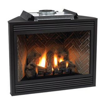
The Tahoe Direct Vent Gas Fireplaces
WARNING: If the information in this
manual is not followed exactly, a fire
or explosion may result causing prop-
erty damage, personal injury or loss
of life.
— Do not store or use gasoline or other
flammable vapors and liquids in the
vicinity of this or any other appliance.
— WHAT TO DO IF YOU SMELL GAS
•
Do not try to light any appliance.
•
Do not touch any electrical switch;
do not use any phone in your build-
ing.
•
Immediately call your gas supplier
from a neighbor's phone. Follow
the gas supplier's instructions.
•
If you cannot reach your gas sup-
plier, call the fire department.
— Installation and service must be per-
formed by a qualified installer, service
agency or the gas supplier.
13369-1-0203
INSTALLATION INSTRUCTIONS
OWNER'S MANUAL
AND
DIRECT VENT
GAS FIREPLACE
MODELS
DVS-30-2
DVS-36-2
DVS-36IP-2
DVS-42-2
DVS-42IP-2
EFFECTIVE DATE
FEBRUARY, 2003
This appliance may be installed in an
aftermarket, permanently located,
manufactured home (USA only) or mobile
home, where not prohibited by state or
local codes.
This appliance is only for use with the
type of gas indicated on the rating plate.
This appliance is not convertible for use
with other gases, unless a certified kit is
used.
WARNING: If not installed, operated and
maintained in accordance with the manu-
facturer's instructions, this product could
expose you to substances in fuel or from
fuel combustion which can cause death or
serious illness.
DVS-30RF-2
DVS-36RF-2
DVS-42RF-2
Page 1
Advertisement
Table of Contents
Troubleshooting

Related Manuals for White Mountain Hearth DVS-30-2, DVS-30RF-2, DVS-36-2, DVS-36IP-2, DVS-36RF-2, DVS-42-2, DVS-42IP-2, DVS-42RF-2


Summary of Contents for White Mountain Hearth DVS-30-2, DVS-30RF-2, DVS-36-2, DVS-36IP-2, DVS-36RF-2, DVS-42-2, DVS-42IP-2, DVS-42RF-2
-
Page 1: Installation Instructions
— Installation and service must be per- formed by a qualified installer, service agency or the gas supplier. 13369-1-0203 INSTALLATION INSTRUCTIONS OWNER'S MANUAL DVS-30-2 DVS-36-2 DVS-42-2 This appliance may be installed in an aftermarket, permanently located, manufactured home (USA only) or mobile home, where not prohibited by state or local codes. -
Page 2: Table Of Contents
Standing Pilot Wiring Diagram ... 28 Standing Pilot Lighting Instructions ... 29 Standing Pilot Troubleshooting ... 30 DVS-36 & DVS-42 Intermittent Pilot Operating Instructions ... 31 DVS-36 & DVS-42 Intermittent Pilot Wiring Diagram ... 31 DVS-36 & DVS-42 Intermittent Pilot Lighting Instructions ... 32 DVS-36 &... -
Page 3: Important Safety Information
Before enclosing the Simpson Dura-Vent vent pipe assembly operate the appliance to ensure it is venting properly. DVS-36 OR DVS-42 IS A HEATING APPLIANCE WHEN HEATER BAFFLE IS INSTALLED, SEE PAGE 7 Do Not Operate This Appliance Without Glass Front Panel Installed. -
Page 4: Safety Information For Users Of Lp Gas
SAFETY INFORMATION FOR USERS OF LP-GAS Propane (LP-Gas) is a flammable gas which can cause fires and explosions. In its natural state, propane is odorless and colorless. You may not know all the following safety precau- tions which can protect both you and your family from an accident. -
Page 5: Introduction
Instructions to Installer 1. Installer must leave instruction manual with owner after installation. 2. Installer must have owner fill out and mail warranty card supplied with the fireplace. 3. Installer should show owner how to start and operate the fireplace. This direct vent gas fireplace is designed to operate with all combustion air being siphoned from the outside of the building and all exhaust gases expelled to the outside of the building. -
Page 6: Specifications
BTU/HR (KW/H) Minmum Height without standoff Width Depth Gas Inlet (Pipe) Control Options & Accessories for All DVS-30, DVS-36 & DVS-42 GWSG-T 750 Millivolt Wall Thermostat (Only used when DVS- 36 or DVS-42 fireplace is converted into a heater.) FRBC-1... -
Page 7: Fireplace Component Installation
Figure 2 Installation of Heater Baffle for DVS-36 or DVS-42 (Figure 3) Your DVS-36 or DVS-42 fireplace is a direct vent gas fireplace. To convert your direct vent gas fireplace into a direct vent gas fireplace heater you will install the heater baffle into the fireplace. -
Page 8: Clearances To Combustibles
CLEARANCES TO COMBUSTIBLES BACK SPACER CLEARANCE TO COMBUSTIBLES BACK SIDE SPACER SIDE FLOOR FLOOR TOP STAND OFF TOP STAND OFF TOP FRAMING LEDGE TOP FRAMING LEDGE SEE MANTLE CHART SEE MANTLE CHART FOR MAXIMUM MANTLE FOR MAXIMUM MANTLE DEPTH SEE MANTLE CHART SEE MANTLE CHART FOR MINIMUM HEIGHT FOR MINIMUM HEIGHT... -
Page 9: Gas Supply
he gas pipeline can be brought in through the right or left side of the appliance. Consult the current National Fuel Gas Code, ANSI Z223.1 CAN/CGA-B149 (.1 or .2) installation code. Recommended Gas Pipe Diameter Pipe Length Schedule 40 Pipe (Feet) Inside Diameter Nat. -
Page 10: Venting Fireplace
Acceptable vertical and horizontal vent run. Unacceptable vertical and horizontal vent run. INSTALLATION Venting Graph (Dimensions in Feet) SIDEWALL VENTING GRAPH SIDEWALL VENTING GRAPH (DIMENSIONS IN FEET) (DIMENSIONS IN FEET) HORIZONTAL RUN HORIZONTAL RUN Figure 10 DVS-36/42 Shown Figure 11 13369-1-0203... - Page 11 Attention: When fireplace is installed in optional full cabinet mantel or corner mantel the (4) four nailing flanges shown in Figure 11 will not be installed on the side of outer casing. The DVS will be attached to the full cabinet mantel or corner mantel with the (2) two nailing flanges located on the top of the outer casing assembly.
- Page 12 VERTICAL, 90 ELBOW WITH HORIZONTAL TERMINATION Figure 14 HORIZONTAL ONLY, STRAIGHT OUT THE BACK 4" TO 5 5/8" 4" TO 5 5/8" PIPE 102mm TO 143mm 102mm TO 143mm 5 5/8"" TO 11 5/8" 5 5/8"" TO 11 5/8" 143mm TO 295mm 143mm TO 295mm 11 1/8""...
- Page 13 CORNER INSTALLATION VERTICAL, 90 ELBOW TO HORIZONTAL OUT THE WALL Figure 17 CORNER INSTALLATION HORIZONTAL, 45 ELBOW TO HORIZONTAL OUT THE WALL WALL FIRESTOP WALL FIRESTOP 4" TO 7 1/2" 4" TO 7 1/2" 102mm TO 191mm 102mm TO 191mm 7 5/8""...
- Page 14 CHART 1 (Figures 20 and 21) Venting with One (1) 90 Elbow or Two (2) 90 Elbows Total Vertical (With Fire Box) V 4.5' minimum 4.5' minimum 5' minimum 6' minimum 7' minimum 8' minimum 25' maximum vertical 20' maximum horizontal run Figure 21 and Chart 1 list examples of possible venting systems using two (2) 90 elbows.
- Page 15 This hole must be 10" high x 10" wide for DVS-30 or 12 3/8" high x 10 3/8" wide for DVS-36/42 with its center line determined by the amount of vertical arise and horizontal run of the termination.
-
Page 16: Termination Clearances
Important! When vent termination exits through foundation less than 20" below siding outcrop, the vent pipe must flush up with the siding. SD-985 for DVS-30 or SD-1284 for DVS-36/42 termination cap must be used. Information on Various Venting Routes and Components Important: It is always best to locate the fireplace in such a way that minimizes the number of offsets and horizontal vent length. -
Page 17: Vent Clearances
*Clearance above grade, veranda, porch, deck or balcony [*12 inches (30cm) minimum] clearance to window or door that may be opened [*12 inches (30cm) minimum for appliances < 100,000 Btuh (30kW) 36 inches (90cm) minimum for appliances > 100,000 Btuh (30kW)] clearance to permanently closed window [minimum 12 inches (30cm) recommended to prevent condensation on window]... -
Page 18: Vent System Identification
Be certain that each succeeding vent component is securely fitted and locked into the preceding component in the vent system. Venting Components Simpson Dura-Vent Part Number Part Number DVS-30 DVS-36/DVS-42 SD-908B SD-1208 6" Pipe Length SD-907B SD-1207 9" Pipe Length... -
Page 19: Dvs-30 Framing And Finishing
DVS-30 FRAMING AND FINISHING Installing Support Brackets (Figure 29) A horizontal pipe support MUST BE used for each 3 feet of horizontal run. The pipe supports should be placed around 8 inch diameter pipe and nailed in place to framing members. There... - Page 20 DVS-30 FRAMING AND FINISHING (continued) Figure 31 Figure 32 Page 20 Figure 33 See "Horizontal Termination (for all Models)" Page 22 and "Vertical Termination (for all Models)" Page 23-24. 13369-1-0203...
-
Page 21: Dvs-36 & Dvs-42 Framing And Finishing
DVS-36 & DVS-42 FRAMING AND FINISHING Installing Support Brackets (Figure 34) A horizontal pipe support MUST BE used for each 3 feet of horizontal run. The pipe supports should be placed around 8 inch diameter pipe and nailed in place to framing members. There... -
Page 22: Dvs-36 & Dvs-42 Framing And Finishing
CAUTION: If exterior walls are finished with vinyl siding, it is necessary to install the vinyl siding standoff SD-950 for DVS-30 or SD-1250 for DVS-36/42. Vinyl siding standoff SD-950 for DVS-30 or SD-1250 for DVS- 36/42 will be installed between the vent termination and the exterior wall. -
Page 23: Vertical Termination (For All Models)
NOTE: This also pertains to vertical vent systems installed on the outside of the building. Slide the vertical top SD-991 for DVS-30 or SD-1291 for DVS- 36/42 over the ends of the vent pipe and secure. (See Figure 41) Installing the Vent System in a Chase A chase is a vertical box like structure built to enclose the gas appliance and/or it's vent system. -
Page 24: Vertical Termination (For All Models)
VERTICAL TERMINATION (For All Models) (continued) Reassembly and Resealing Vent Pipe System Attach adapter pipe to vent cover in either the vertical or horizontal position, replace horizontal and vertical pipe lengths, elbows and horizontal or vertical termination kit. All vent system components lock into place by sliding the concentric pipe section with four (4) equally spaced interior beads onto the appliance collar or previously installed component end with four (4) equally spaced indented sections. - Page 25 TOP VIEW OF LOG SET REAR LOG DVS-30 Placement of glowing embers. Figure 46 TOP VIEW OF LOG SET REAR LOG DVS-36 and DVS-42 Placement of glowing embers. Figure 47 Page 25...
-
Page 26: Flame Appearance
Placement of the glowing embers (rock wool) is very individual and light coverage of the areas indicated will provide your best effects. We recommend separation of the rock wool by hand and make your coverage as light and fluffy as possible. Place just enough rock wool on the burner to obtain the glow and a gold yellow flame. -
Page 27: Remote On/Off Switch
Figure 50 STANDING PILOT OPERATING INSTRUCTIONS ON/OFF/REMOTE Switch DVS is equipped with an ON/OFF/REMOTE switch. A wire harness is attached to the ON/OFF/REMOTE switch. The red, black and green (wires) female push-ons attach to the ON/OFF/ REMOTE switch. At the opposite end of the wire harness, the black and green (wires) female push-ons attach to the gas valve. -
Page 28: Standing Pilot Wiring Diagram
STANDING PILOT OPERATING INSTRUCTIONS (continued) Manual Operation 1. Turn ON/OFF/REMOTE switch to REMOTE position. 2. Turn wall thermostat OFF. 3. Turn accessory, FRBC-1, FRBTC-1, FREC-1 or FWS-1, ON. Appliance is now in the manual mode. You must turn the appliance ON or OFF with appropriate accessory. Wall Thermostat Operation 1. -
Page 29: Standing Pilot Lighting Instructions
STANDING PILOT LIGHTING INSTRUCTIONS FOR YOUR SAFETY READ BEFORE LIGHTING WARNING: If you do not follow these instructions exactly, a fire or explosion may result causing property damage, personal injury or loss of life. A. This fireplace has a pilot which must be lighted by hand. When lighting the pilot, follow these instructions ex- actly. -
Page 30: Standing Pilot Troubleshooting
STANDING PILOT TROUBLESHOOTING With proper installation and maintenance, your new Gas Direct Vent Fireplace should provide years of trouble-free service. If you do experience a problem, refer to the Trouble Shooting Guide below. This guide will assist a qualified service person in the diagnosis of problems and the corrective action to be taken. -
Page 31: Dvs-36 & Dvs-42 Intermittent Pilot Operating Instructions
DVS-36 & DVS-42 INTERMITTENT PILOT OPERATING INSTRUCTIONS The intermittent pilot (120/24 volt system) is ON when the main burner is ON. When the main burner is OFF the intermittent pilot is OFF. The pilot flame should envelop 3/8 to 1/2 inch (10 to 13mm) of the tip of the flame rod. -
Page 32: Dvs-36 & Dvs-42 Intermittent Pilot Lighting Instructions
DVS-36 & DVS-42 INTERMITTENT PILOT LIGHTING INSTRUCTIONS FOR YOUR SAFETY READ BEFORE LIGHTING WARNING: If you do not follow these instructions exactly, a fire or explosion may result causing property damage, personal injury or loss of life. A. This appliance is equipped with an ignition device which automatically lights the pilot. -
Page 33: Dvs-36 & Dvs-42 Intermittent Pilot Troubleshooting
DVS-36 & DVS-42 INTERMITTENT PILOT TROUBLESHOOTING GENERAL: All furnaces have been fire-tested to check for proper operation. This includes, main burner flame, pilot flame, fan operation, fan control, limit control and automatic valve operation. If the furnace fails to function on initial installation, it is advisab\le to re-check the following: 1. - Page 34 DVS-36 & DVS-42 INTERMITTENT PILOT TROUBLESHOOTING If the pilot does not light, or the pilot flame current is not at least 1.0 uA and steady, the module will not energize the second main valve and the main burner will not light.
-
Page 35: Arc Length
Important 1. The following service procedures are provided as a gen- eral guide. 2. Meter readings between gas control and ignition module must be taken within the trial for ignition period. Once the ignition module locks out, the system must be reset by setting the thermostat down for at least one minute before continuing. -
Page 36: Dvs-36 & Dvs-42 Intermittent Pilot Troubleshooting
DVS-36 & DVS-42 INTERMITTENT PILOT TROUBLESHOOTING (continued) START Turn gas supply off. Turn thermostat to call for heat. Power to module. (24 VAC nominal) Spark across Igniter/sensor gap. Turn gas supply on. Pilot burner lights? Spark stops when pilot is lit? -
Page 37: Rf Standing Pilot Operating Instructions
RF STANDING PILOT OPERATING INSTRUCTIONS Features • Self powered millivolt receiver/valve • Thermostat performance • Auto mode • Self powered millivolt control • Integrated Valve Electronics • Failure analysis • Pilotstat interlock • F or C temperature units Functions • Flame powered system •... -
Page 38: Rf Wiring Diagram With Optional Blower
RF WIRING DIAGRAM Figure 54 Page 38 13369-1-0203... -
Page 39: Rf Standing Pilot Lighting Instructions
RF STANDING PILOT LIGHTING INSTRUCTIONS STANDING PILOT LIGHTING INSTRUCTIONS 13369-1-0203 Page 39... -
Page 40: Maintenance And Service
MAINTENANCE AND SERVICE PLEASE NOTE It is normal for appliances fabricated of steel to give off some expansion and/or contraction noised during the start up or cool down cycle. Similar noises are found with your furnace heat exchanger or car engine. It is not unusual for your Empire gas fireplace to give off some odor the first time it is burned. -
Page 41: How To Order Repair Parts
#44 ORIFICE - NAT AIR SHUTTER COUPLING (NAT GAS ONLY) BURNER BOX ASSEMBLY BURNER SUPPORT - LEFT BURNER SUPPORT - RIGHT PILOT ASSEMBLY - NATURAL (DVS-30) PILOT ASSEMBLY - LP (DVS-30) THERMOPILE (DVS-30) THERMOCOUPLE (DVS-30) PILOT ASSEMBLY - NATURAL (DVS- 30RF) PILOT ASSEMBLY - LP (DVS-30RF) THERMOPILE (2 REQ’D) (DVS-30RF) -
Page 42: Dvs-36 Parts List
11404 OUTER WRAPPER - LEFT 11403 OUTER WRAPPER BACK 11405 OUTER WRAPPER - RIGHT 10779 CORNER SHIELD 10054 JUNCTION BOX WELDED ASSEMBLY (DVS- 36IP) 10018 AIR DILLUTION COVER PLATE 10574 CORNER BRACE 2 10573 CORNER BRACE 1 11521 OUTER WRAPPER BOTTOM WELDED... -
Page 43: Dvs-42 Parts List
11423 OUTER WRAPPER - LEFT 11422 OUTER WRAPPER BACK 11424 OUTER WRAPPER - RIGHT 10779 CORNER SHIELD 10054 JUNCTION BOX WELDED ASSEMBLY (DVS- 42IP) 10018 AIR DILLUTION COVER PLATE 10574 CORNER BRACE 2 10573 CORNER BRACE 1 11420 OUTER WRAPPER BOTTOM WELDED... -
Page 44: Parts View
PARTS VIEW Page 44 13369-1-0203... -
Page 45: Accessory Parts
Frame — Brass Frame — High Gloss Black Frame — Black Brass Louvers High Gloss Black Louvers Brass Window Trim Junction Box Model Number Variable Speed FKA-160 Single Speed FBB1A DVS-BL-30 DVS-BL-36 DVS-BL-42 DVP1A-30-1 DVP1A-36-1 DVP1A-42-1 DVFB-AK-30 FB-AK-2 DVSBF-36BR-1 DVSBF-42BR-1 DVSBF-42BR-1 FBF-30BP-2... -
Page 46: Optional Variable Speed Blower Installation Instructions
VARIABLE SPEED BLOWER INSTALLATION INSTRUCTIONS Optional FB-BK-2 Blower Installation Factory Installed FB-BK-RF Blower 1. If applicable, turn OFF electric supply to fireplace. 2. Lower bottom louver. 3. With a 5/16" socket, loosen but do not remove either left screw or right screw that attaches bottom louver to fireplace side. -
Page 47: Fan Switch
Wiring The appliance, when installed, must be electrically grounded in accordance with local codes or, in the absence of local codes, with the National Electrical Code, ANSI/NFPA 70, if an external electrical source is utilized. This appliance is equipped with a three-prong [grounding] plug for your protection against shock hazard and should be plugged directly into a properly grounded three-prong receptacle. -
Page 48: Optional Single Speed Blower Installation Instructions
OPTIONAL SINGLE SPEED BLOWER INSTALLATION INSTRUCTIONS FBB1A Blower Installation 1. If applicable, turn OFF electric supply to fireplace. 2. Lower bottom louver. 3. With a 5/16" socket, loosen but do not remove either left screw or right screw that attaches bottom louver to fireplace side. 4. - Page 49 Wiring The appliance, when installed, must be electrically grounded in accor- dance with local codes or, in the absence of local codes, with the National Electrical Code ANSI/NFPA No. 70, if an external electrical source is utilized. This appliance is equipped with a three-prong [grounding] plug for your protection against shock hazard and should be plugged directly into a properly grounded three-prong receptacle.
-
Page 50: Optional Fresh Air Intake Installation Instructions
OPTIONAL FRESH AIR INTAKE INSTALLATION INSTRUCTIONS Optional Fresh Air Intake Kit (Figure 1) Installation of our 6" fresh air intake kit is simple and easy to complete. This system MUST BE installed before the fireplace is enclosed with finishing material. The air will be drawn into the cooling layer of the fireplace and be completely separated from the combustion casing of the direct vent fireplace. -
Page 51: Parts List
6. Insert damper rod through damper rod bracket and 3/8" diameter hole in cover plate. Insert damper rod into 1/4" diameter hole in damper door tab. Place smooth side of 1/2" diameter pushnut over end of damper rod. Press the pushnut onto the damper rod approximately 1/8". The pushnut will prevent the damper rod from falling out of 1/4"... -
Page 52: Optional Brick Liner Installation Instructions
Nine Eighteen Freeburg Ave. Belleville, Illinois 62220-2623 Page 52 BRICK LINER KIT DVS-BL-30-2, DVS- BL-36-2, DVS DVP1A-30-1, DVP1A-36-1, DVP1A-42-1 7. Repeat Step 5 and Step 6 to attach the second side panel to fireplace. 8. Attach combustion dome diverter into interior, top of firebox with three (3) 10 x 1/2"...
Need help?
Do you have a question about the DVS-30-2, DVS-30RF-2, DVS-36-2, DVS-36IP-2, DVS-36RF-2, DVS-42-2, DVS-42IP-2, DVS-42RF-2 and is the answer not in the manual?
Questions and answers