Table of Contents
Advertisement
Quick Links
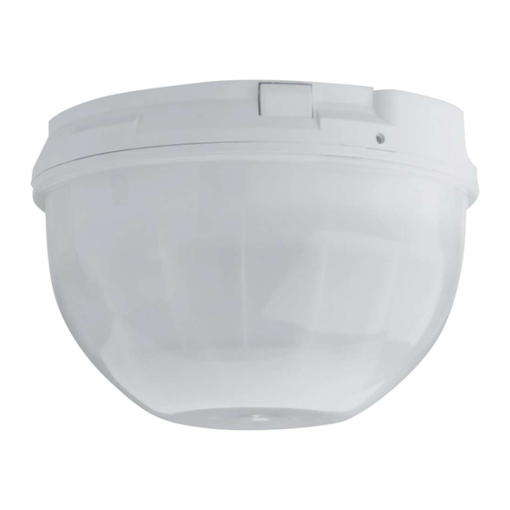
DS9360 TriTech Ceiling Mount
PIR/ Microwave Intrusion Detector
1.0
Specifications
•
Dimensions (HxDia): 3.5 in. x 5.25 in. (8.9 cm x 13.3 cm)
•
Coverage:
360° by 60 ft. (18.3 m) diameter
coverage when mounted on 8 to 18 ft.
(2.4 to 5.5 m) high ceilings. Pattern
consists of 64 zones grouped into 16
barriers, with one additional zone
looking straight down from the unit
(sabotage). Each barrier is 30 ft. (9.2 m)
long and 4.4 ft. (1.3 m) wide at 30 ft.
(9.2 m). Choice of two optical modules
depending on ceiling height.
•
Input Power:
6.0 to 15.0 VDC; 18 mA standby, 75 mA
in alarm with LEDs enabled. Use only
an Approved Limited Power Source.
•
Standby Power:
There is no internal standby battery.
Standby power must be provided by an
Approved Limited Power Source.
Eighteen mAh required for each hour of
standby time needed. For UL Listed
Requirements, 72 mAh standby current
is required.
•
Sensitivity:
Field selectable for Intermediate and
High.
•
Alarm Relay:
Silent-operating Form "C" relay. Contacts
rated 125 mA, 28 VDC maximum for DC
resistive loads. To be connected to a
SELV (Safety Extra-Low Voltage) circuit
only. Do not use with capacitive or
inductive loads.
•
Tamper:
Normally Closed (with cover in place)
tamper switch. Contacts rated at
28 VDC, 125 mA maximum. To be
connected to a SELV (Safety Extra-Low
Voltage) circuit only. Connect tamper
circuit to a 24-hour protection circuit.
•
Temperature Range: The storage and operating range is
-40°F to +120°F (-40°C to +49°C). For UL Listed
Requirements, the range is +32°F to
+120°F (0°C to +49°C).
•
Compliance: This device complies with Part 15 of the FCC
Rules and with RSS-210 of Industry and Science Canada.
Operation is subject to the following two conditions:
(1) this device may not cause harmful interference, and
(2) this device must accept any interference received,
including interference that may cause undesirable
operation.
Changes or modifications not expressly approved by Bosch
Security Systems can void the user's authority to operate the
equipment.
EN50131-2-4 Grade 2 Environmental Class II
2.0
Installation Considerations
•
Never install the detector in an environment that causes an
alarm condition in one technology. Good installations start with
the LED OFF when there is no target motion. It should never be
left to operate with the tri-color LED in a constant or intermittent
green, yellow, or red condition.
•
Point the unit away from outside traffic (roads/alleys).
NOTE:
Microwave energy will pass through glass and most
common non-metallic construction walls.
•
Avoid installations where rotating machines (e.g. ceiling fans)
are normally in operation within the coverage pattern. Point the
unit away from glass exposed to the outdoors and objects that
may change temperature rapidly.
NOTE:
The PIR detector will react to objects rapidly changing
temperature within its field-of-view.
•
Eliminate interference from nearby outside sources.
3.0
Mounting
•
Select a location likely to intercept an intruder moving beneath
and across the coverage pattern. Recommended mounting
height range is 8 to 18 feet (2.4 to 5.5 m).
•
The surface should be solid and vibration-free. (i.e. Drop tiles
should be secured if the area above the tiles is used as an air
return for HVAC systems).
•
Open the cover by turning counterclockwise. One side of the
cover will remain attached to the base of the detector. Do not
attempt to entirely remove the cover.
The Cover remains
attached to the
Enclosure
Cover
•
Remove the base from the enclosure by pressing the two
enclosure release tabs inward while lifting the enclosure away
from the base.
Hint:
Slightly rock the enclosure side-to-side during removal to
overcome the friction caused by the base-to-enclosure
terminal pins.
•
Route wiring as necessary to the rear of the base and through
the center hole.
Note:
Be sure all wiring is de-energized before routing.
•
Firmly mount the base. Depending on local regulations, the
base may be directly surface mounted using anchors, mollies,
or wing-nuts, or may be mounted to standard 4-inch octagonal
or square electrical boxes.
Base
Enclosure Release Tabs
Enclosure
Advertisement
Table of Contents

Related Manuals for Bosch DS9360 TriTech


Summary of Contents for Bosch DS9360 TriTech
- Page 1 Hint: Slightly rock the enclosure side-to-side during removal to operation. overcome the friction caused by the base-to-enclosure Changes or modifications not expressly approved by Bosch terminal pins. Security Systems can void the user’s authority to operate the equipment. •...
- Page 2 Note: The DS9360 base will not completely cover a 4-inch Wiring square box. Where aesthetics are important, a 4-inch Only apply power after all connections have been octagonal box is recommended. made and inspected. Do not coil excess wiring Hint: Mounting to removable ceiling tiles is not recommended inside detector.
- Page 3 This ensures an alarm output prior to arming the system. 9.3 Reading Bosch Security Systems, Inc. Product Date Codes For Product Date Code information, refer to the Bosch Security Systems, Inc. Web site at: http://www.boschsecurity.com/datecodes/. DS9360 Installation Guide ©...
- Page 4 © 2011 Bosch Security Systems, Inc. 3/11 130 Perinton Parkway, Fairport, New York 14450 DS9360 Installation Guide www.boschsecurity.com P/N: F01U069640-05 Page 4...
Need help?
Do you have a question about the DS9360 TriTech and is the answer not in the manual?
Questions and answers