Table of Contents
Advertisement
Quick Links
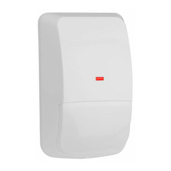
Installation Instructions
for the DS778
ASIC-Based
Passive Infrared Intrusion Detector
1.0 Specifications
• Input Power:
6.0 VDC to 15.0 VDC; 18 mA @ 12.0 VDC
• Standby Power:
There is no internal standby battery.
Connect to DC power sources capable of
supplying standby power if primary power
fails. For each hour of standby time
needed, 18 mAh are required. For UL
Certificated Installations, A minimum of
4 hours (72 mAh) is required.
• Coverage:
200 ft. by 15 ft. (60 m by 4.5 m)
• Sensitivity:
Adjustable for Intermediate or High.
• Alarm Relay:
Form "C" reed relay with contacts rated at
28 VDC, 125 mA max. for DC resistive
loads.
• Tamper Switch:
Normally Closed (with cover in place)
tamper switch. Contacts rated at 28 VDC,
125 mA max.
• Temperature:
The storage and operating range is -40°F
to +120°F (-40°C to +49°C). For UL
Certificated installations, the temperature
range is +32°F to +120°F (0°C to +49°C).
• Options:
B328 Gimbal Mount Bracket, B335 Low
Profile Mount Bracket, B338 Ceiling Mount
Bracket, TC6000 Test Cord.
Note:
Misalignment of the detector when using an optional
mounting bracket may reduce range.
2.0 Mounting
2.1 Mounting Considerations
• Select a location that is most likely to intercept an intruder moving
across the coverage pattern. The recommended mounting height
range is 6.5 ft. to 8.5 ft. (2 m to 2.6 m).
* The mounting surface should be solid and vibration free.
• Avoid direct hot and/or cold drafts, direct sunlight, heat sources,
windows, air conditioning outlets, and small animals.
• This detector won't detect through glass.
• See Section 8.0 Coverage Patterns .
2.2 Surface or Corner Mounting
Note:
For bracket mounting, refer to the installations supplied
with the bracket.
• Remove the cover. Insert a thin flathead screwdriver into the
notch at the bottom of the cover and pry up.
• Remove the chassis screw in the upper right corner of the
assembly (see Figure A ). To remove the circuit board/mirror unit
from the enclosure, push the circuit board/mirror unit toward the
top of the enclosure until it clears its four retainer tabs, then lift
out.
• Open two holes (see Figure A ) for surface or corner mounting.
Chassis
Screw
1 2 3
- +
NO
C
NC
T T
T-Strip
O PE N
Noise
Configuration
Voltage
Switches
LED
+2
+2
Tamper Switch
0
0
-8
-8
-16
-16
Figure A - Location of Major Items -
Circuit Board and Detector Enclosure
• Mark the location for the mounting screws. Use the enclosure
as a template. Pre-start the mounting screws.
• Open the appropriate wiring knockout and route the wiring
through (see Section 3.0 Wiring ).
• Securely attach the detector.
• Replace the circuit board/mirror unit.
• Adjust the mirror.
Note:
Excessive handling of the mirror surfaces may lead to
performance degradation.
-
Adjust vertically from +2° to -18° by sliding the mirror forward
or back. See Figures B and C to set the correct Vertical Angle
based on the mounting height and desired range.
Mounting Height [ft. (m)]
6.5 (2)
7.5 (2.3)
8.5 (2.6)
Figure B - Mounting Height/Range Chart
-
The angle adjust markings are on the sides of the mirror
(see Figure C ).
+2
Set
0
at
-8
-16
-1°
Figure C - Setting Vertical Angle
-
Slide the mirror forward or back until the angle hash marks
are in-line with the markers on each side of the frame.
Wiring Knockouts
Corner
Mounting
Holes (4)
Bracket
Mounting
Hole
Surface Mounting Holes
or Single Gang
Box Holes (2)
Vertical Angle Setting
100 ft. (30 m)
200 ft. (60 m)
-2°
-1°
-2°
-2°
-2°
-3°
+2
+2
0
0
-8
-8
-16
-16
Mirror
Advertisement
Table of Contents

Subscribe to Our Youtube Channel
Related Manuals for Bosch DS778


Summary of Contents for Bosch DS778
- Page 1 • Open two holes (see Figure A ) for surface or corner mounting. Installation Instructions Wiring Knockouts for the DS778 ASIC-Based Chassis Screw Passive Infrared Intrusion Detector Corner 1 2 3 T-Strip Mounting O PE N Holes (4) Noise 1.0 Specifications...
- Page 2 • Walk test the unit from both directions to determine the boundaries. • If the desired range cannot be achieved, try angling the mirror up or down to assure the coverage pattern is not aimed too high or low. Page 2 © 2004 Bosch Security Systems DS778 Installation Instructions...
- Page 3 For readings outside these limits; eliminate the cause, re-point the unit slightly, or mask off the affected zones. View of Front Polished Surface Long Range Coverage Top View meters feet Side View meters feet DS778 Installation Instructions © 2004 Bosch Security Systems Page 3...
- Page 4 © 2004 Bosch Security Systems 03/04 130 Perinton Parkway, Fairport, New York, USA 14450-9199 DS778 Installation Instructions Customer Service: (800) 289-0096; Technical Support: (888) 886-6189 P/N: 47884D Page 4...
Need help?
Do you have a question about the DS778 and is the answer not in the manual?
Questions and answers