
Related Manuals for PRESONUS CENTRAL STATION


Summary of Contents for PRESONUS CENTRAL STATION
- Page 1 CENTRAL STATION S T U D I O C O N T R O L C E N T E R USER’S MANUAL version 1.1 © 2004 Pr e S o n u s A u d i o E l e c t r o n i c s , I n c o r p o r a t e d .
- Page 2 Some states do not allow limitations on how long an implied warranty lasts, so the above limitation may not apply to you. In no event will PreSonus be liable for incidental, consequential or other damages resulting from the breach of any express or implied warranty, including, among other things, damage to property, damage based on inconvenience or on loss of use of the product, and, to the extent permitted by law, damages for personal injury.
-
Page 3: Table Of Contents
TABLE OF CONTENTS 1 Overview 1.1 Introduction 1.2 Features 2 Controls & Connections 2.1 Front Panel Layout 2.2 Talkback & Phones 2.3 Cue / Main Select 2.4 Meter 2.5 Passive Speaker Control 2.6 Back Panel Layout 2.7 Connectors 2.8 Power Supply 3 Operation 3.1 Quick Start Up 3.2 Hook Up Diagram... -
Page 4: Overview
CENTRAL STATION before trying to hook it up to your system. Thank you, once again, for buying our product and may we wish you Good Luck and enjoy your CENTRAL STATION! 1 . -
Page 5: Controls & Connections
METERING The CENTRAL STATION has dual fast-acting 30-segment peak/hold LED's for accurate metering. The front panel of the CENTRAL STATION includes both dBu and dBfs scale as well as peak/hold clear switch and meter alignment switch for additional metering options. -
Page 6: Front Panel Layout
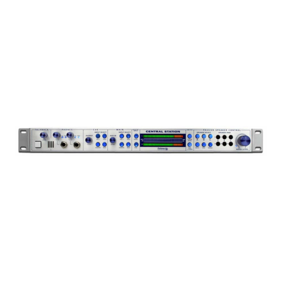
CONTROLS & CONNECTIONS 2 . 1 F R O N T P A N E L L A Y O U T The front panel of the CENTRAL STATION is divided into four sections – Talkback/Headphones, Cue/Main Select, Meter, Passive Speaker Control 2 . -
Page 7: Cue / Main Select
2 . 3 C U E / M A I N S E L E C T The CENTRAL STATION is loaded with separate CUE and MAIN signal paths. The CUE signal path includes the TALKBACK microphone signal and is intended for sending this signal to the recording artist via external headphone amp, or the two on board headphone amp. -
Page 8: Passive Speaker Control
CONTROLS & CONNECTIONS • CLEAR PEAK –The meters on the CENTRAL STATION have a PEAK hold feature in which the RED clip LED will remain on until the CLEAR PEAK button is pressed. • CALIBRATE – You can calibrate the meters on your CENTRAL STATION to match the metering on your other equipment. -
Page 9: Back Panel Layout
2 . 6 B A C K P A N E L L A Y O U T The back panel of the CENTRAL STATION is divided into six sections: DIGITAL INPUTS, SPEAKER OUTPUTS, LINE OUTPUTS, ANALONG INPUTS, CONSOLE REMOTE CONTROL and TALKBACK. -
Page 10: Connectors
Make sure you always turn off power amp and powered monitors before changing any cable connections or turning your CENTRAL STATION on or off. Loud pops can clicks can occur when making cable connections or powering up or down your CENTRAL STATION. -
Page 11: Operation
6. Using a flat screwdriver turn all PASSIVE SPEAKER OUTPUTS completely clockwise. 7. Power up your CENTRAL STATION by connecting power supply to rear of CENTRAL STATION and into electrical outlet power source or power strip, then power up your power amp or powered monitors. - Page 12 OUTPUT B, and a subwoofer to SPEAKER OUTPUT C. 23. Set the power amps on your powered monitors or speaker amps to their mid level position. 24. Play audio into the TRS 1 input of the CENTRAL STATION and select TRS 1 in the MAIN INPUT SELECT section.
-
Page 13: Hook Up Diagram
OPERATION 3 . 2 H O O K U P D I A G R A M... -
Page 14: Meter Calibration Procedure
To calibrate the meters on your CENTRAL STATION to an external DAW or audio device: 1. Input a 1kHz 0dBu sine wave test tone to ANY input on your CENTRAL STATION. Select the input you are using in the MAIN INPUT SELECT section on the front panel. In a computer based recording system, this can be accomplished by creating an audio channel and assign a test tone to it by either a tone generator, plug-in or wav file. -
Page 15: Application Diagrams
3 . 4 A P P L I C A T I O N D I A G R A M S The CENTRAL STATION is an extremely flexible tool and can be used in all stages of the recording and music production process. - Page 16 MIXDOWN / MASTERING SET UP Using the CENTRAL STATION digital to analog converter – Below is a typical mix down or mastering set up where the CENTRAL STATION’s 24 bit / 192k digital to analog converter is being used to compare the music...
-
Page 17: Technical
TECHNICAL 4 . 1 S P E C I F I C A T I O N S Audio Inputs TRS1&2 Type ¼” TRS Passive-Balanced Input Impedance 2K-5K Ohm (Speaker load and Trim level dependent) S/N Ratio Greater than 140dB THD+N Less than .0005% (1KHz @ 0dBu) Frequency Response... - Page 18 TECHNICAL Talkback Dynamic Microphone Input Type XLR Female Balanced Input Impedance 2400 Ohm Internal Microphone Type Electret Condenser Sensitivity -42dB Mic Preamp Gain Range 15-55dB Input Meters Type 30 segment LED w/ Peak Hold Range -48dB to +18dB (-66dBfs to 0dBfs) Accuracy Better than .25dB Frequency Range...
-
Page 19: Block Diagram
TECHNICAL 4 . 2 B L O C K D I A G R A M INPUT METERS INPUT SWITCHING MAIN OUT TRS1 MASTER VOLUME SPEAKER A MUTE MONO TRS2 SPEAKER B COAX SPEAKER C TOSLINK SPDIF OUTPUT SWITCHING REMOTE PHONES FOOTSWITCH INTERNAL...
Need help?
Do you have a question about the CENTRAL STATION and is the answer not in the manual?
Questions and answers