Table of Contents
Advertisement
Quick Links
Download this manual
See also:
Owner's Manual
Advertisement
Table of Contents

Subscribe to Our Youtube Channel
Related Manuals for PRESONUS ADL600


Summary of Contents for PRESONUS ADL600
- Page 1 USER’S MANUAL version 1.1 © 2005, Pr e S o n u s A u d i o E l e c t r o n i c s , I n c o r p o r a t e d . A l l r i g h t s r e s e r ve d .
- Page 2 Some states do not allow limitations on how long an implied warranty lasts, so the above limitation may not apply to you. In no event will PreSonus be liable for incidental, consequential or other damages resulting from the breach of any express...
-
Page 3: Table Of Contents
TABLE OF CONTENTS 1 Overview 1.1 Introduction 1.2 Features 2 Controls & Connections 2.1 Front Panel Layout 2.3 Back Panel Layout 2.4 Power and Ground 3 Operation 3.1 Input Sources 3.2 Microphones 3.3 Instruments 3.4 Line input 3.5 Hook up diagrams 1. -
Page 4: Overview
1 . 1 I N T R O D U C T I O N Thank you for purchasing the PreSonus ADL 600. The ADL 600 utilizes the highest quality components to insure optimum performance for an infinite period of time. We believe the ADL 600 to be an exceptional-sounding microphone preamplifier and an exceptional value. -
Page 5: Features
OVERVIEW 1 . 2 F E A T U R E S The following information is a summary of your ADL 600’s features: All Tube, Dual Transformer Microphone Pre-Amplifier. Your ADL 600 is a discrete Class A high voltage all tube, dual-transformer microphone preamplifier designed for high gain (+73dB), high headroom (+30dB), low noise (-100dB S/N ratio) and ultimate sonic performance –... -
Page 6: Controls & Connections
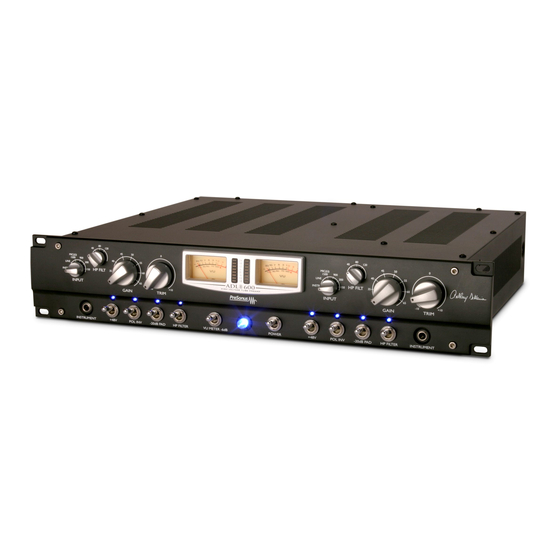
2 CONTROLS & CONNECTIONS 2 . 1 F R O N T P A N E L L A Y O U T The front panel of the ADL 600 is laid out so that if you split the front panel down the middle the controls and metering for channel 1 are on the left hand side and the controls and metering for channel 2 are on the right hand side. - Page 7 CONTROLS & CONNECTIONS +48V: The 48 volts supplied by way of the XLR connector, provides power for condenser mics and any other devices requiring continuous phantom power through the XLR input. This power is supplied at a constant level to prevent any degradation of audio quality.
-
Page 8: Back Panel Layout
CONTROLS & CONNECTIONS 2 . 2 B A C K P A N E L L A Y O U T Connectors All Input and Output connectors are transformer balanced. XLR with the following wiring standard: PIN 1 PIN 2 High PIN 3 NOTE: The LINE INPUT does not pass signal unless the INPUT selector switch... -
Page 9: Operation
3 OPERATION 3 . 1 I N P U T S O U R C E S The ADL 600 can be used with a variety of input sources: microphones, instruments and line level devices. 3 . 2 M I C R O P H O N E S The ADL 600 works great with all types of microphones including dynamic, ribbon and condenser microphones. -
Page 10: Hook Up Diagrams
OPERATION 3 . 5 H O O K U P D I A G R A M S The following hook up diagrams are provided to give you a few examples in connecting your ADL 600 for various recording applications: 1. -
Page 11: Keyboards, Syths, Drum Machines
OPERATION 3. Keyboards, Synths and Drum Machines 4. Stereo buss signal conditioning during mix-down or stereo mastering... -
Page 12: Applications
OPERATION 3 . 6 A P P L I C A T I O N S The following are a few two-channel recording applications for you to get you started in using your ADL 600. These are by no means the only way to record these instruments. -
Page 13: Electric Guitar
OPERATION Electric Guitar – Place a dynamic or ribbon microphone an inch or two away from the speaker of the guitar amplifier. Experiment with exact location. If you are recording an amp with multiple speakers experiment with each one to see if one sounds better than the others. -
Page 14: Acoustic Guitar
OPERATION Acoustic Guitar – Place a small diaphragm condenser microphone pointed at the 12 fret approximately eight inches away. Place a large diaphragm condenser microphone pointed at the bridge of the guitar approximately twelve inches from the guitar. Experiment with distances and microphone placement. Another popular method is using an XY microphone placement with two small diaphragm condenser microphones. -
Page 15: Bass Guitar
OPERATION Bass Guitar (Direct and Speaker) Plug electric bass guitar into a passive direct box. Connect instrument output from the passive direct box to a bass amplifier. Place a dynamic microphone an inch or two away from the speaker and connect microphone to ADL 600 microphone input. -
Page 16: Drum Overheads
OPERATION Drum Overheads (XY example) – Place two small diaphragm condenser microphones on an XY stereo microphone holder (bar). Position microphones so that each microphone is at a 45 degree angle pointed down at the drum kit approximately seven or eight feet up. Experiment with height. -
Page 17: Snare Drum
OPERATION Snare Drum – (top and bottom) Place dynamic microphone pointed at the center of the snare making sure drummer will not hit it. Place small diaphragm condenser microphone under the drum pointed at the snares. Experiment with microphone placement of both microphones. Also experiment with inverting the phase of the bottom microphone. -
Page 18: Technical
4 TECHNICAL... -
Page 19: Specifications
TECHNICAL 4 . 2 T E C H N I C A L S P E C I F I C A T I O N S Input Impedance Microphone ..........Selectable, 150/300/900/1500 Ohm Balanced Line ..................2KOhm Instrument ..................100KOhm Maximum Input Level Microphone (1500Ohm, +20dB Pad out) ..........+5dBu Microphone (1500Ohm, +20dB Pad in) ..........+25dBu...
Need help?
Do you have a question about the ADL600 and is the answer not in the manual?
Questions and answers