Advertisement
Quick Links
Designed for use on SWG Series Power Vent Hoods for controlling oil fired heating appliances with 120
VAC controls.
I
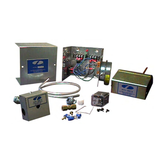
TEMS INCLUDED IN KIT
THESE INSTRUCTIONS MUST REMAIN WITH EQUIPMENT
SYSTEM CONTROL KIT
Model: CK-62
:
1) Junction box with mounted pressure switch and relay base
1) 120 VAC Relay
1) 2 Ft. Length of 1/4 inch aluminum tubing
1) 1/4 inch tubing connector
1) Flexible conduit connector
1) WMO-1 Secondary Safety Switch
1) PPC-4 Post Purge Switch
DO NOT DESTROY
Advertisement

Related Manuals for Field Controls 46149200


Summary of Contents for Field Controls 46149200
- Page 1 SYSTEM CONTROL KIT Model: CK-62 Designed for use on SWG Series Power Vent Hoods for controlling oil fired heating appliances with 120 VAC controls. TEMS INCLUDED IN KIT 1) Junction box with mounted pressure switch and relay base 1) 120 VAC Relay 1) 2 Ft.
-
Page 2: Mounting Junction Box
MOUNTING JUNCTION BOX The junction box can be mounted at the venter or remotely mounted away from the venter. (See Figure 1 & Figure 2) 1. Remove one of the knockouts from the side of the junction box where the pressure switch is mounted. Install the flexible conduit connector onto the CK-62 Junction Box and secure with fastening nut. - Page 3 PPC-4 POST PURGE KIT NOTE: All Oil Fired Appliances must have a post purge kit installed. Installation of a POST PURGE KIT is REQUIRED for oil fired appliances for the purpose of venting combustion products after the burner has shut down. This kit has an adjustable thermally activated sensing device that continues to vent the flue system until the temperature drops below switch opening temperature.
-
Page 4: Wiring Instructions
WIRING INSTRUCTIONS Wire the venter motor and controls in accordance with the National Electrical Code, manufacturer's recommendations and/or applicable local codes. UNIT MUST BE GROUNDED. Check ground circuit to make certain that the unit has been properly grounded. The wiring should be protected by an over current circuit device rated at 15 amperes. CAUTION must be taken to ensure that the wiring does not come into contact with any heat source. - Page 5 Diagram B – Oil Fired System: Wiring with Electronic Primary Page 5...
- Page 6 Diagram C – Typical Wiring for Oil Fired Warm Air Furnace with a Honeywell ST9103 Control Board Page 6...
- Page 7 Diagram D – Riello Burner Application Page 7...
- Page 8 Diagram E – Multiple Oil Fired Systems Page 8...
- Page 9 PRESSURE SWITCH SENSING TUBE INSTALLATION 1. Attach the 1/4 inch tubing connector to the pressure tube on the SWG Venter. (See Figure 3) 2. Connect the supplied 1/4" aluminum tubing to the tubing connector. Route the tubing to the CK-62 Junction Box and connect the tubing to the pressure switch.
-
Page 10: Troubleshooting Hints
TROUBLE SHOOTING HINTS 1. Main burner does not fire when thermostat calls for heat with venter operating. a. Check pressure switch adjustment. b. Check fuel flow. c. Check wiring connections between pressure switch and burner. d. Check pressure switch for continuity across terminals, during venter operation. 2. - Page 11 INSTALLATION INFORMATION CK-62 MODEL NO.:_____________________________________________________________ INSTALLER'S NAME:______________________________________________________ INSTALLER'S COMPANY:__________________________________________________ INSTALLER'S PHONE NO.:_________________________________________________ DATE OF INSTALLATION: _________________________________________________ Page 11...
- Page 12 Page 12 P/N 46149200 Rev E 11/05...
Need help?
Do you have a question about the 46149200 and is the answer not in the manual?
Questions and answers