Field Controls WMO-1 Manual
Blocked vent switch
Hide thumbs
Also See for WMO-1:
- Installation and maintenance instructions (4 pages) ,
- Manual (8 pages)
Table of Contents
Advertisement
Available languages
Available languages
Quick Links
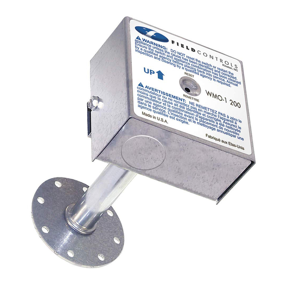
BLOCKED VENT SWITCH
The WMO-1 Blocked Vent Switch is recommended for installation with an oil fired appliance that normally
operates with its vent system under negative pressure. This device is intended to detect a blocked vent
system, responds to hot flue gases backing up through its heat transfer tube, and can be wired to shut off the
oil burner. It requires manual resetting.
WARNING: Read the installation instructions carefully and completely before proceeding with
the installation.
WARNING: Do NOT reset the device or restart the appliance unless the cause has been identified
and corrected by a qualified agency. Insure the switch appliance combination has been cleaned by
a qualified agency before placing back into service. Annual inspection and cleaning by a qualified
agency is required.
•
Wiring MUST be in accordance with the current Canadian Electrical Code and any other applicable
federal, provincial and local code requirements.
•
For installations in the USA, all wiring shall be in accordance with the National Electrical Code and
applicable local codes.
•
For continued safe operation, the appliance-switch combination is required to be inspected and
maintained annually by a qualified agency. Failure to properly maintain the appliance-switch
combination can lead to death, personal injury and/or property damage.
READ THESE INSTRUCTIONS CAREFULLY AND COMPLETELY BEFORE PROCEEDING WITH THE INSTALLATION.
This device MUST be installed by a qualified agency in accordance with the manufacturer's installation instructions. The definition of
a qualified agency is: any individual, firm, corporation or company which either in person or through a representative is engaged
in, and is responsible for, the installation and operation of HVAC appliances, who is experienced in such work, familiar with all the
precautions required, and has complied with all the requirements of the authority having jurisdiction.
Installed By:
Model: WMO-1
Please retain these instructions after installation.
Phone:
www.fieldcontrols.com
ITEMS SUPPLIED IN THIS KIT:
1-Blocked vent switch assembly
1-Gasket
1-Instruction sheet
Installation Date:
Advertisement
Table of Contents

Subscribe to Our Youtube Channel
Related Manuals for Field Controls WMO-1


Summary of Contents for Field Controls WMO-1
- Page 1 1-Gasket 1-Instruction sheet The WMO-1 Blocked Vent Switch is recommended for installation with an oil fired appliance that normally operates with its vent system under negative pressure. This device is intended to detect a blocked vent system, responds to hot flue gases backing up through its heat transfer tube, and can be wired to shut off the oil burner.
-
Page 2: Installation
INSTALLATION Mounting in the vent pipe SEE THE APPLIANCE MANUFACTURER’S INSTRUCTIONS FOR THE SPECIFIC LOCATION. IF THE APPLIANCE MANUFACTURER DOES NOT SPECIFY A LOCATION, REFER TO FIGURE 1. 1. Drill or pierce a clean hole (about ⁄ " diameter) in the vent pipe near the appliance outlet. (See Figure 1) 2. -
Page 3: Current Rating
Diagram A Honeywell R7184B & Carlin 60200-02 Diagram B Riello CURRENT RATING 120 VAC 10 FL AMPS 60 LR AMPS 240 VAC 5 FL AMPS 30 LR AMPS page 3... -
Page 4: Maintenance
Disconnect power to the appliance. Remove the two screws holding on the WMO-1 blocked vent switch assembly cover. Remove the cover. Remove the two screws holding the control box to the heat transfer tube assembly. The control box slides, unlocking it from the heat transfer tube assembly DO NOT DENT OR SCRATCH THE SURFACE OF THE THERMAL SWITCH. - Page 5 1-Joint 1-Fiche d’instructions Il est recommandé d’installer le commutateur pour ventilation bloquée WMO-1 avec un appareil au mazout qui fonctionne normalement avec son système de ventilation sous dépression. Ce dispositif est prévu pour détecter un système de ventilation bloqué, se formant dans son tube de transfert thermique et pouvant être câblé...
-
Page 6: Instructions De Câblage
ATTENTION: Débrancher toute alimentation électrique à l’appareil lors du câblage du commutateur pour ventilation bloquée. AVERTISSEMENT: Le canal de connexion du contacteur doit être monté horizontalement, a moins que ce ne soit indiqué différemment par le fabricant d’appareils. Figure 1 INSTRUCTIONS DE CÂBLAGE SUIVEZ L’APPAREIL DE FABRICATION DE CÂBLAGE DIAGRAMME. -
Page 7: Entretien
7. Débrancher toute alimentation à l’appareil. 8. Dévisser les deux vis qui maintiennent le couvercle de l’ensemble de commutateur our ventilation bloquée WMO-1. 9. Retirer le couvercle. 10. Retirer les deux vis qui maintiennent le boîtier de commande à l’ensemble du tube de transfert thermique. -
Page 8: Warranty
WARRANTY For warranty about this or any Field Controls product, visit: www.fieldcontrols.com/warranty Phone: 252.522.3031 • Fax: 252.522.0214 www.fieldcontrols.com © Field Controls, LLC P/N 46086800 Rev F 04/15...
Need help?
Do you have a question about the WMO-1 and is the answer not in the manual?
Questions and answers