Table of Contents
Advertisement
Quick Links
This symbol is intended to
alert the user to the pres-
ence of uninsulated "dan-
gerous voltage" within the
product's enclosure that may be of suf-
ficient magnitude to constitute a risk of
electric shock to persons.
IMPORTANT! FOR YOUR PROTECTION, PLEASE READ THE FOLLOWING:
WATER AND MOISTURE: Appliance should not be used near water (near a bathtub, washbowl,
kitchen sink, laundry tub, in a wet basement, or near a swimming pool, etc). Care should be taken
so that objects do not fall and liquids are not spilled into the enclosure through openings.
POWER SOURCES: The product should be connected to a power supply only of the type described
in the operating instructions or as marked on the appliance.
GROUNDING OR POLARIZATION: Precautions should be taken so that the grounding or polar-
ization is not defeated.
POWER CORD PROTECTION: Power supply cords should be routed so that they are not likely
to be walked on or pinched by items placed upon or against them, paying particular attention
to cords at plugs, convenience receptacles, and the point where they exit from the appliance.
SERVICING: The user should not attempt to service the appliance beyond that described in the
operating instructions. All other servicing should be referred to qualified service personnel.
FUSING: If your unit is equipped with a fuse receptacle, replace only with the same type fuse.
Refer to replacement text on the unit for correct fuse type.
SAFETY INSTRUCTIONS (EUROPEAN)
The conductors in the AC power cord are colored in accordance with the following code.
GREEN & YELLOW—Earth
U.K. MAIN PLUG WARNING: A molded main plug that has been cut off from the cord is
unsafe. NEVER UNDER ANY CIRCUMSTANCES SHOULD YOU INSERT A DAMAGED
OR CUT MAIN PLUG INTO A POWER SOCKET.
REPLACEMENT PARTS LIST FOR HT AMPS
10
9
8
7
THIS UNIT CONTAINS
6
HIGH VOLTAGE COMPONENTS
INSIDE. REFER SERVICING TO
QUALIFIED SERVICE PERSONNEL.
HT Series Chassis, Cables & Hardware
REF DESCRIPTION
PART #
1
Fuse Holder
23-81116
Line
Fuse Value
120 VAC 2A, 250V, Slow Blow, 3AG
15-01512
230 VAC 1A, 250V, Slow Blow, 3AG
15-01524
2
Binding Post, Dual, Black/Red, Long
03-10450
3
Circuit Board Assembly (Includes all PCB's)
80-01528
4
Unichassis
10-01509
5
Bracket, Tiedown, IC
10-63008
6
10-01501
7
Switch, Power
25-31350
8
Knob, Power Amp
07-09001
9
Mount, Toroid Cap
10-15004
Insulator, Toroid Pad (Not shown)
03-15010
10 Transformer, Power, Toroid
See Chart
11 Cover, Chassis (Not shown)
10-06005
12 Foot, .875x.3125 (Not shown)
03-19682
13 Power Cord, AC, 16AWG (Not shown)
05-01604
Parts List For HT150 PCB Sub Assemblies
REF
DESCRIPTION
A1
Op-amp, Low noise
A2
Op-amp, Low noise
C1
Capacitor, Electrolytic, 4700µF, 50V
C2
Capacitor, Electrolytic, 4700µF, 50V
C3
Capacitor, Electrolytic, 470µF, 25V
C4
Capacitor, Electrolytic, 470µF, 25V
C5
Capacitor, Electrolytic, 10µF, 50V
C6
Capacitor, Electrolytic, 10µF, 50V
C7
Capacitor, Electrolytic, 10µF, 50V
C8
Capacitor, Mylar, .047µF, 250V
C100
Capacitor, Ceramic, 56pF
This symbol is
CAUTION
intended to alert the
user to the presence of
RISK OF ELECTRIC SHOCK
important operating
DO NOT OPEN
and maintenance (servicing) instruc-
tions in the literature accompanying
the appliance.
BLUE—Neutral
BROWN—Live
1
2
3
3
3
5
REF
DESCRIPTION
QTY
C101
Capacitor, Ceramic, 56pF
1
C102
Capacitor, Electrolytic, 10µF, 50V
C103
Capacitor, Electrolytic, 10µF, 50V
1
C104
Capacitor, Ceramic, 120pF
1
C105
Capacitor, Ceramic, 120pF
2
C106
Capacitor, Electrolytic, 10µF, 50V
1
C107
Capacitor, Poly, .0047µF, 100V
1
C108
Capacitor, Poly, .022µF, 100V
2
C109
Capacitor, Electrolytic, 10µF, 50V
1
C110
Capacitor, Poly, .1 µF, 100V
1
C111
Capacitor, Poly, .1 µF, 100V
2
C112
Capacitor, Electrolytic, 10µF, 50V
1
C113
Capacitor, Electrolytic, 10µF, 50V
2
C114
Capacitor, Mylar, 0.22µF
1
C115
Capacitor, Electrolytic, 10µF, 50V
1
C200
Capacitor, Ceramic, 56pF
4
C201
Capacitor, Ceramic, 56pF
1
C202
Capacitor, Electrolytic, 10µF, 50V
C203
Capacitor, Electrolytic, 10µF, 50V
C204
Capacitor, Ceramic, 120pF
PART #
C205
Capacitor, Ceramic, 120pF
60-45580
C206
Capacitor, Electrolytic, 10µF, 50V
60-45580
C207
Capacitor, Poly, .0047µF, 100V
42-47251
C208
Capacitor, Poly, .022µF, 100V
42-47251
C209
Capacitor, Electrolytic, 10µF, 50V
47-47125
C210
Capacitor, Poly, .1 µF, 100V
47-47125
C211
Capacitor, Poly, .1 µF, 100V
47-10051
C212
Capacitor, Electrolytic, 10µF, 50V
47-10051
C213
Capacitor, Electrolytic, 10µF, 50V
47-10051
C214
Capacitor, Mylar, 0.22µF
41-47322
C215
Capacitor, Electrolytic, 10µF, 50V
45-56052
D1
Diode, 6A, 200V, MR752
LIMITED WARRANTY
Your Carvin product is guaranteed against failure for ONE YEAR. Carvin will service and supply all
parts at no charge to the customer providing the unit is under warranty. Shipping costs are the respon-
sibility of the customer. CARVIN DOES NOT PAY FOR PARTS OR SERVICING OTHER THAN OUR
OWN. A COPY OF THE ORIGINAL INVOICE IS REQUIRED TO VERIFY YOUR WARRANTY. Carvin
assumes no responsibility for horn drivers or speakers damaged by this unit. This warranty does
not cover, and no liability is assumed, for damage due to: natural disasters, accidents, abuse, loss
of parts, lack of reasonable care, incorrect use, or failure to follow instructions. This warranty is in
lieu of all other warranties, expressed or implied. No representative or person is authorized to rep-
resent or assume for Carvin any liability in connection with the sale or servicing of Carvin products.
CARVIN SHALL NOT BE LIABLE FOR INCIDENTAL OR CONSEQUENTIAL DAMAGES.
When RETURNING merchandise to the factory, you may call for a return authorization number.
Describe in writing each problem. If your unit is out of warranty, you will be charged the current
FLAT RATE for parts and labor to bring your unit up to factory specifications.
HELP SECTION
1) WILL NOT TURN ON
Check the power to the unit. Check for tripped circuit breakers, unplugged extension cords or
power-strip switches that may be turned off. Check the fuse. If a dark brownish color or no wire
can be seen within the glass fuse, then replace. The unit may be perfectly fine but occasionally
the fuse may blow because of high AC voltage surges. After the fuse has been replaced with the
proper value and if the fuse fails again, the product will require servicing (be sure to use a slow
blow fuse if required). Check your input and speaker output cables.
2) MAINTAINING YOUR EQUIPMENT
Avoid spilling liquids or allowing any other foreign matter inside the unit. The panel of your unit can
be wiped from time to time with a dry or slightly damp cloth in order to remove dust and bring back
the new look. As with all pro gear, avoid prolonged use in caustic environments (salt air). When
used in such an environment, be sure the amplifier is adequately protected by rack, covers, etc..
RISK OF ELECTRIC SHOCK
REF
DESCRIPTION
D2
Diode, 6A, 200V, MR752
D3
Diode, 6A, 200V, MR752
D4
Diode, 6A, 200V, MR752
D5
LED, Small Yellow
D6
Diode, 1A, 200V, 1N4003
D100
Diode, 1A, 200V, 1N4003
D101
Diode, 1A, 200V, 1N4003
D102
LED, Small Green
4
D103
LED, Small Red
D200
Diode, 1A, 200V, 1N4003
D201
Diode, 1A, 200V, 1N4003
D202
LED, Small Green
D203
LED, Small Red
H1
Cable, Ribbon, 24AWG, 8Pin
H2
Cable, Ribbon, 24AWG, 8Pin
H3
Cable, Ribbon, 24AWG, 8Pin
J100
Jack, 1/4" 7P Plastic, 24mm
J101
XLR, Female, Neutrik
J102
Jack, 1/4" 3P Plastic, 24mm
J200
Jack, 1/4" 7P Plastic, 24mm
J201
XLR, Female, Neutrik
J202
Jack, 1/4" 3P Plastic, 24mm
P100
Pot, B10KΩ, 41 Click, W/BRKT
P200
Pot, B10KΩ, 41 Click, W/BRKT
PRI 1
Terminal 90deg, .250 QC
PRI 2
Terminal 90deg, .250 QC
Q100
Trans, Darlington, NPN, 0.5A, 30V
Q101
Trans, Darlington, NPN, 0.5A, 30V
Q200
Trans, Darlington, NPN, 0.5A, 30V
Q201
Trans, Darlington, NPN, 0.5A, 30V
PART #
QC1
Zierick/Keystone, Straight, .250 QC
45-56052
QC2
Zierick/Keystone, Straight, .250 QC
47-10051
QC3
Zierick/Keystone, Straight, .250 QC
47-10051
R1
Resistor 2W, ±5%, 1.5K
45-12152
R2
Resistor 2W, ±5%, 1.5K
45-12152
R3
Resistor 1W, ±5%, 4.7K
47-10051
R4
Resistor 1/4W, ±5%, 24K
46-47212
R5
Resistor 1/4W, ±5%, 22K
46-22312
R6
Resistor 1/4W, ±5%, 10K
47-10051
R7
Resistor 1/4W, ±5%, 33K
46-10412
R100
Resistor 1/4W, ±5%, 22K
46-10412
R101
Resistor 1/4W, ±5%, 22K
47-10051
R102
Resistor 1/4W, ±5%, 22K
47-10051
R103
Resistor 1/4W, ±5%, 22K
46-22412
R104
Resistor 1/4W, ±5%, 680Ω
47-10051
R105
Resistor 1/4W, ±5%, 5.6K
45-56052
R106
Resistor 1/4W, ±5%, 2.2K
45-56052
R107
Resistor 1/4W, ±5%, 2.7K
47-10051
R108
Resistor 1/4W, ±5%, 22K
47-10051
R109
Resistor 1/4W, ±5%, 10K
45-12152
R110
Resistor 1/4W, ±5%, 910Ω
45-12152
R111
Resistor 1/4W, ±5%, 1K
47-10051
R112
Resistor 1/4W, ±5%, 1.5K
46-47212
R113
Resistor 1/4W, ±5%, 24K
46-22312
R114
Resistor 1/4W, ±5%, 2.2K
47-10051
R115
Resistor 1/4W, ±5%, 47K
46-10412
R116
Resistor 1/4W, ±5%, 3.3K
46-10412
R117
Resistor 1/4W, ±5%, 470K
47-10051
R118
Resistor 1/4W, ±5%, 470K
47-10051
R119
Resistor 1W, ±5%, 4.7K
46-22412
R120
Resistor 1W, ±5%, 4.7K
47-10051
R121
Resistor 1/2W, ±5%, 22Ω
60-75200
REFER SERVICING TO QUALIFIED SER-
CAUTION
VICE PERSONNEL! THIS UNIT CON-
TAINS HIGH VOLTAGE INSIDE!
PART #
REF
60-75200
R122
60-75200
R200
60-75200
R201
60-24251
R202
61-40030
R203
61-40030
R204
61-40030
R205
60-75330
R206
60-75320
R207
61-40030
R208
61-40030
R209
60-75330
R210
60-75320
R211
05-24175
R212
05-24255
R213
05-24175
R214
21-06457
R215
21-40000
R216
21-06453
R217
21-06457
R218
21-40000
R219
21-06453
R220
71-10301
R221
71-10301
R222
06-40060
S1
06-40060
S2
60-00014
U100
60-00014
U200
60-00014
Z1
60-00014
Z2
06-40050
06-40050
06-40050
54-15030
54-15030
53-47035
50-24045
50-22045
50-10045
50-33045
50-22041
50-22041
50-22041
50-22041
50-68025
50-56035
50-22035
50-27035
50-20045
50-12045
50-91025
50-10035
50-15035
50-24045
50-22035
50-47045
50-33035
50-47055
50-47055
53-47035
53-47035
52-22015
DESCRIPTION
PART #
Resistor 1/4W, ±5%, 47K
50-47045
Resistor 1/4W, ±5%, 22K
50-22041
Resistor 1/4W, ±5%, 22K
50-22041
Resistor 1/4W, ±5%, 22K
50-22041
Resistor 1/4W, ±5%, 22K
50-22041
Resistor 1/4W, ±5%, 680Ω
50-68025
Resistor 1/4W, ±5%, 5.6K
50-56035
Resistor 1/4W, ±5%, 2.2K
50-22035
Resistor 1/4W, ±5%, 2.7K
50-27035
Resistor 1/4W, ±5%, 22K
50-20045
Resistor 1/4W, ±5%, 10K
50-12045
Resistor 1/4W, ±5%, 910Ω
50-91025
Resistor 1/4W, ±5%, 1K
50-10035
Resistor 1/4W, ±5%, 1.5K
50-15035
Resistor 1/4W, ±5%, 24K
50-24045
Resistor 1/4W, ±5%, 2.2K
50-22035
Resistor 1/4W, ±5%, 47K
50-47045
Resistor 1/4W, ±5%, 3.3K
50-33035
Resistor 1/4W, ±5%, 470K
50-47055
Resistor 1/4W, ±5%, 470K
50-47055
Resistor 1W, ±5%, 4.7K
53-47035
Resistor 1W, ±5%, 4.7K
53-47035
Resistor 1/2W, ±5%, 22Ω
52-22015
Resistor 1/4W, ±5%, 47K
50-47045
Switch, DPDT, 2 Position
25-32833
Switch, DPDT, Push, PC Mtg
25-02201
Op-amp, Power
60-72940
Op-amp, Power
60-72940
Zener Diode,16V ±5%, 1N4745A
61-47450
Zener Diode,16V ±5%, 1N4745A
61-47450
Advertisement
Table of Contents

Related Manuals for CARVIN HT150


Summary of Contents for CARVIN HT150
- Page 1 Care should be taken resent or assume for Carvin any liability in connection with the sale or servicing of Carvin products. so that objects do not fall and liquids are not spilled into the enclosure through openings.
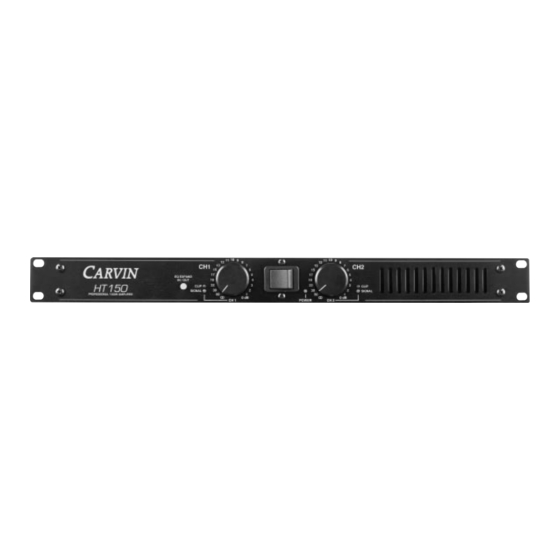
- Page 2 This will provide the best possible protec- brushed anodized aluminum face plate, large recessed knobs and tion during shipment. CARVIN and the shipping company are not liable for any damage caused heavy-duty steel chassis reflect the manufacturing quality within.
- Page 3 (15 on the dial). 11. BRIDGE MODE— 25V/70V DISTRIBUTION SYSTEMS The HT150 can be operated in bridge mode if you require a 25V / 70V 4. CHANNEL SIGNAL INDICATOR The green SIGNAL LED indicators will start to flash when there is a signal distribution speaker system or a high powered mono (single channel) amp.
- Page 4 The preferred method of connecting input signals is with balanced XLR’s (two conductors cause your amplifier to oscilate because of the internal shield. plus a shield wire, such as Carvin professional XLR cables). Balanced input signals provide the highest gain and best noise rejection. 1/4” stereo cables are also capable of providing balanced input by using a stereo plug (tip-positive, ring-negative &...
Need help?
Do you have a question about the HT150 and is the answer not in the manual?
Questions and answers