Bosch 120 Series, MC-120-DKM Manual
- Product information (17 pages)
- Also fits for
- Mc-120-dkm
Advertisement
Product description
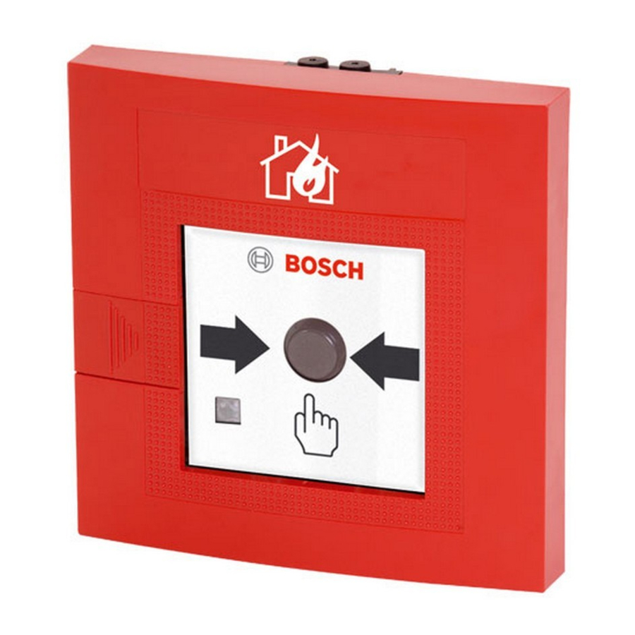
The series 120 non−automatic fire detector is used for manual alarm triggering in conventional line technology (GLT). The line is monitored according to the principle of voltage reduction and increase.
The Form H detectors are designed for exterior areas, the Form G detectors for interior areas.
Overview of non−automatic fire detectors, series 120
Manual call points
- FMC−120−DKM−G−R Manual call point for interior areas (Form G), red
- FMC−120−DKM−H−R Manual call point for exterior areas (Form H), red
Manual call points
- FMC−120−DKM−G−B Manual call point for interior areas (Form G), blue
- FMC−120−DKM−H−B Manual call point for exterior areas (Form H), blue
- FMC−120−DKM−G−Y Manual call point for interior areas (Form G), yellow
Stop device
- FMC−120−EST−G−B Stop device for interior areas (Form G), blue
Features
- Manual call point and stop device: Trigger alarm by pushing the button. After alarm triggering, the push button is adjusted.
- Detector query routines with evaluation and multiple transmission.
- Display (LED) for triggered alarms or inspection evaluation.
- Second contact with connections for panel control.
- Same design for interior use (Form G) and exterior use (Form H).
- Available in different colour variants; see order overview.
- For the red colour variants, a burning house" is applied to the detector housing in the factory.
- Variable labelling is possible with foil sets for the blue and yellow colour variants.
- For exterior use in extreme environmental conditions, the detector is equipped with an especially resistant PC board (parylene layering) and with a seal in the detector door.
Planning notes
- Non−automatic fire detectors must be mounted visibly along escape and rescue routes (e.g. exits, passageways, stairwells) and be easily accessible.
- An installation height of 1400 mm (200 mm), measured from the middle of the push button to the floor, must be maintained.
- Non−automatic fire detectors must be sufficiently lit with sunlight or another light source (including emergency lighting if present).
- The distance between non−automatic fire detectors should not exceed 100 m according to DIN 14 675 or 80 m according to VdS.
- In high risk areas, non−automatic fire detectors should be installed at intervals of max. 40 m (VDE 0833 Part 2, Point 7.2.6).
Maximum number of detectors that may be connected
In accordance with VdS guidelines, a maximum of 10 non−automatic fire detectors may be connected to a primary line.
The test detector can be used for primary lines with automatic fire detectors. It is connected to the electrical end of the primary line (max. 1 test detector per primary line).
Norms, guidelines and planning recommendations
Additional norms, guidelines, and planning recommendations with respect to installation location etc. must be taken into account (see fire detector manual).
The regulations of the local fire services must be observed.

Use in explosive areas
 All non−automatic detectors from fire detector series 120 conform to device category 3G, gas group IIB and temperature class T6, in accordance with the European guideline 94/9/EG (ATEX). Thus the detectors may be used in Zone 2 areas where there is danger of explosion! |
Limiting values:
- Detectors may only be operated with central units whose line output is energy−limited according to EN 50021. This applies to all Bosch fire panels (BMZ).
- The line voltage (Umax) must not exceed 33 V!
- The maximum current (Imax) must be limited to 130 mA!
Fire detector cable:
- Only fire detector cables that conform to DIN VDE 0814 may be used.
- The total cable capacity (Cmax) must not exceed 1 F!
- The total cable inductivity (Lmax) must not exceed 0.01 H! The cable type J−Y(ST)Y08, in accordance with DIN VDE 0815 (table 10), has a capacity of 120 F at a length of 1000 m.
Labelling variants
The detectors can be individually adapted to the location/application with optional labelling variants. This excludes detector variants FMC−120−DKM−G−R and
FMC−120−DKM−H−R, to which the burning house" symbol has already been applied.
The self−adhesive labelling foils are stuck on the front panel of the detector.
Order contents
Basic model
| Product ID | DU* | Designation |
| F01U011951 | Pc | FMC−120−DKM−G−R, Manual call point for interior areas (Form G), red |
| F01U011952 | Pc | FMC−120−DKM−H−R, Manual call point for exterior areas (Form H), red |
| F01U011953 | Pc | FMC−120−DKM−G−B, Manual call point for interior areas (Form G), blue |
| F01U011954 | Pc | FMC−120−DKM−H−B, Manual call point for exterior areas (Form H), blue |
| F01U011955 | Pc | FMC−120−DKM−G−Y, Manual call point for interior areas (Form G), yellow |
| F01U012763 | Pc | FMC−120−EST−G−B, Stop device for interior areas (Form G), blue |
Labelling foils
| Product ID | DU* | Designation |
| F.01U.012.951 | PAK | FMC−FST−DE, Pre−cut and labelled foil sets for the top labelling field (1 PACK = 5 sheets with 12 labelling variants) |
| F.01U.033.170 | PAK | FMX−FSO−GLT, Pre−cut foil sets for the top labelling field (1 PAK = 10 sheets with 6 labelling variants). Appropriate for printing at standard laser printers. The required print file is available on the WinPara disk. |
Accessories / Spare parts
| Product ID | DU* | Designation |
| 3.790.170.005 | Pc | Out of order" − Metal stop sign |
| 3.756.630.007 | Pc | Red plastic key (ASA) for detector door |
| F.01U.025.845 | PAK | FMC−SPGL−DEIL, Replacement glass pane, dimensions 80 x 80 x 0.9 mm (1 PACK = 5 pieces) |
Device structure
The non−automatic fire detector is available in several variants and essentially consists of the following elements.

| Pos. | Designation |
| 1 | Plastic housing |
| 2 | Cable ducts (interchangeable), for cable inlet and outlet. The cable can also be ducted through openings in the rear wall of the housing. |
| 3 | Connection terminal strip |
| 4 | Detector door with replaceable glass pane, hidden lock (and seal, for Form H) |
| 5 | Glass pane |
| 6 | Display (LED) |
| 7 | PC board (with protective coating for Form H) The PC board is clipped onto the floor of the housing. |
| 8 | Trigger mechanism (clipped onto the PC board), consisting of plastic frame and push button with spring. |
| 9 | Reset lever (locking mechanism only for manual call points) |
Functional description
Manual call point
Manual call point and stop device: In the event of an alarm, the glass pane (2) is broken first, then the manual call point (3) is pressed hard.
This activates the microswitch for alarm triggering and the display LED (4) flashes.
A locking mechanism holds the pressed push button down.
The pressed push button is reset by manually activating the reset lever (5) or by opening the detector door (1) ⇒ The alarm is reset and the display LED goes out (4).

Functional test
Manual call point and stop device: To trigger the alarm, press the manual call point (3) hard. The display LED (4) flashes. Use the reset lever (5) to return the manual call point to the starting status.
Test detector
A maximum of 1 test detector (1) may be connected to the electrical end of the primary line. Up to 30 automatic fire detectors may be connected to the primary line to be tested. The test detector is supplied by the fire panel.

Installation
- The non−automatic fire detector is designed for wall mounting.
- The installation height, according to VdS regulations, is 1400 mm (± 200 mm) from the floor to the centre of the push button.
- The connection cables can be surface or flush−mounted.
- The cable ducting should be carried out using the intended openings in the housing (see Cable duct).
- The installation location is to be selected so that approximately 35 mm space remains free on the right−hand side for opening the door.
Installation dimensions (view: housing rear wall interior)

Cable duct
Surface−mounted cable duct

Flush−mounted cable duct

Installation variants for fire hose cabinets

| Pos. | Description |
| 1 | Installation depth version 1: min. 36 mm |
| 2 | Installation depth version 2: 14 mm |
| 3 | Installation depth version 3: approx. 30 mm With this version, it is not necessary to open the door of the hose box e.g. for maintenance. |
Connection
Detailed wiring diagrams and bridge assignments for connection to different fire panels are shown in the wiring diagram manual.

 In order to reach an alarm resistance of 820 Ohm in current gain operation, resistor R6 must be removed. For other operating modes (voltage reduction), see the wiring diagram manual for the corresponding fire panel.


| Do not remove the end of line resistor from the last detector! It must be removed from all other detectors. |
Notes on maintenance and service
For maintenance and inspection work on security systems, the regulations of DIN VDE 0833 apply in Germany; these regulations refer to the maintenance intervals as per the manufacturer's instructions.
- Bosch ST recommends a functional and visual inspection at least once a year.
- Maintenance and inspection work should be carried out regularly and by trained personnel.
Repair
In the event of a defect, the entire unit is exchanged.
Additional documentation
 For those with the appropriate access authorisation, see Bosch ST ExtraNet at www.boschbest.de for the updated product information and the installation manual as a downloadable PDF file. For those with the appropriate access authorisation, see Bosch ST ExtraNet at www.boschbest.de for the updated product information and the installation manual as a downloadable PDF file. |
Technical specifications
| Technical specifications | |
| Operating voltage | 24 V DC (16.2 V DC to 30 V DC) |
| Current consumption | specified by the respective security system |
| Protection category as per EN 60529 − Form H (exterior) − Form G (interior) | IP 54 IP 52 |
| Permissible ambient temperature − Form H (exterior) − Form G (interior) | −25C to +70C / −13F to 158F −10C to +55C / 14F to 131F |
| Standard (except FMC−120−DKM−G−Y) | EN 54−11 |
| Standard for FMC−120−DKM−G−Y | EN 12094−3 |
| Colours | RAL 5005 signal blue RAL 1003 signal yellow RAL 3001 signal red |
| Housing material | Plastic, ASA (Acrylonitrile−Styrene−Acrylate Terpolymer) |
| Dimensions (W x H x D) | 135 x 135 x 37 mm / 5.31 x 5.31 x 1.38 inches |
| Weight | 224 g |
Table of abbreviations
| AHB | = Wiring diagram manual |
| BMZ | = Fire panel |
| BM | = Fire detector |
| DIN | = German Institute for Standardisation |
| DKM | = Manual call point |
| EMZ | = Intrusion control panel |
| EN | = European standard |
| GMZ | = Danger detection system |
| KI | = Customer service information |
| LED | = Light Emitting Diode |
| LSN | = Local Security Network |
| SM | = Single action call point |
| UGM | = Universal danger detection system |
| VDE | = Association of German Electrical Engineers |
| VdS | = VdS Schadenverhütung GmbH |
Documents / ResourcesDownload manual
Here you can download full pdf version of manual, it may contain additional safety instructions, warranty information, FCC rules, etc.
Advertisement


Need help?
Do you have a question about the 120 Series and is the answer not in the manual?
Questions and answers