
Related Manuals for Samsung AirDresser DF60A8100 Series


Summary of Contents for Samsung AirDresser DF60A8100 Series
- Page 1 AirDresser Model Name : DF60A8500CG (18”) DF10A9500CG (24”) DF60A8500** DF60A8100** DF10A9500** SERVICE Manual AirDresser CONTENTS 1. Safety Instructions 2. Features and Speci ications 3. Disassembly and Reassembly 4. Troubleshooting...
- Page 2 CONTENTS 1. Safety Instructions ..................1 1-1.
- Page 3 This Document can not be used without Samsung’s authorization. 1. SAFETY INSTRUCTIONS 1-1. SAFETY INSTRUCTIONS FOR SERVICE ENGINEERS ► Be sure to observe the following instructions to operate the product correctly and safely to prevent possible accidents and hazards while servicing.
- Page 4 This Document can not be used without Samsung’s authorization. WHILE SERVICING WARNING • Check if the power plug and outlet are damaged, flattened, cut or otherwise degraded. 4 If faulty, replace it immediately. (Failing to do so may result in electric shock or fire.) • Completely remove any dust or foreign material from the housing, wiring and connection parts.
- Page 5 This Document can not be used without Samsung’s authorization. PRECAUTIONS BEFORE INSTALLATION CAUTION • Install it on a hard and level floor. 4 It may cause abnormal vibration, noise, or breakdown. • Avoid direct sunlight and humid places, and install in a well-ventilated place.
- Page 6 Do not perform grounding on gas pipes, plastic pipes, telephone lines, etc. - It can lead to electric shock or explosion. NOTE Please purchase a grounding line from Samsung Electronics Service Center and connect it to the rear of the product. 4 _ Safety Instructions...
- Page 7 This Document can not be used without Samsung’s authorization. 2. FEATURES AND SPECIFICATIONS 2-1. FEATURES OF THE PRODUCT Features Description • Circulating care provided from the outer to inner lining with the wind. • Stable without vibrations and silent without noise.
- Page 8 This Document can not be used without Samsung’s authorization. Features Description [Basic principle of operation] X company : Heatpump+Steam+Moving hanger Heatpump+Steam+ Air Shower+Deodorizing/Dust filter “Clicking” noise and vibration Breathe in dust Moving hanger falling off the clothes Basic principle of...
- Page 9 This Document can not be used without Samsung’s authorization. Features Description • Odor from clothing removed + Odor degradation for fresher clothes. Deodorization Method Comparison AirDresser (Our company) X company Deodorizing filter All odors can be removed Water-soluble odors only...
- Page 10 This Document can not be used without Samsung’s authorization. ▶ Premium Design - Bespoke Air Dresser with New Color. - 7 types of 18-inch and 3 types of 24-inch colors are introduced. 8 _ Features and Specifications...
- Page 11 This Document can not be used without Samsung’s authorization. 2-2. SPECIFICATIONS OF THE PRODUCT - 18“ Mode DF60T8300KG DF60T8700BG DF60T8700CG DF60T8300WG Image Door color Real Black Burgundy mirror Crystal mirror Classic white Appearance Door material GLASS MIRROR MIRROR GLASS Door Variation - (built in Hinge) ←...
- Page 12 This Document can not be used without Samsung’s authorization. - 18“ NEW model Mode DF60A8500CG DF60A8500WG DF60A8500PG DF60A8500EG Image Crystal mirror Door color Glam white(glass) Glam pink(glass) Satin beige(glass) (mirror) Appearance Door material MIRROR GLASS GLASS GLASS Door Variation (Built-In Hinge) ←...
- Page 13 This Document can not be used without Samsung’s authorization. - 18“ NEW model Mode DF60A8500UG DF60A8500FG DF60A8500YG DF60A8100TG Image Door color Satin sky blue(glass) Forest green(glass) SUN yellow (PCM) Kota white(PCM) Appearance Door material GLASS GLASS GLASS Door Variation (Built-In Hinge) ←...
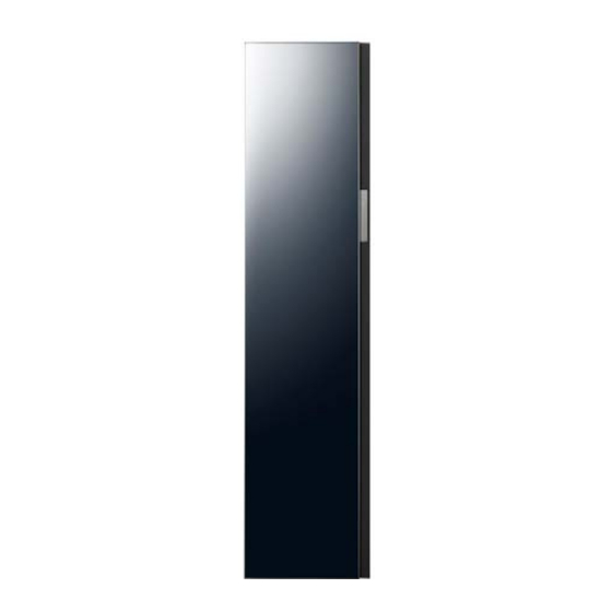
- Page 14 This Document can not be used without Samsung’s authorization. - 18“ NEW model Mode DF60A8500HG DF60A8100HG Image Door color Kota charcoal (PCM) Kota charcoal (PCM) Appearance Door material Door Variation (Built-In Hinge) (Built-In Hinge) Basic Fine Dust Filter - (Mesh Filter)
- Page 15 This Document can not be used without Samsung’s authorization. - 24“ Mode DF10T9300KG DF10T9700BG DF10T9700CG Image Door color Real Black Burgundy mirror Crystal mirror Appearance Door material GLASS MIRROR MIRROR Door Variation (Built-In hinge) ← ← Basic Fine Dust Filter ←...
- Page 16 This Document can not be used without Samsung’s authorization. - 24“ NEW model Mode DF10A9500CG DF10A9500EG DF10A9500VG DF10A9500FG Image Door color Crystal mirror (mirror) Satin beige (glass) Clean NAVY (glass) Forest green (glass) Appearance Door material MIRROR GLASS GLASS GLASS...
- Page 17 This Document can not be used without Samsung’s authorization. - 24“ NEW model Mode DF10A9500YG DF10A9500WG Image Door color SUN yellow (glass) Glam white (glass) Appearance Door material GLASS GLASS Door Variation (Built-In hinge) ← Basic Fine Dust Filter ←...
- Page 18 This Document can not be used without Samsung’s authorization. 2-3. SPACE FOR INSTALLATION - 18in • The minimum space required for safe normal operation is as below: - Distance between the product and the wall Product top / wall: 25 mm, Product side / wall: 14 mm, Product rear / wall: 15 mm...
- Page 19 This Document can not be used without Samsung’s authorization. - 24in • The minimum space required for safe normal operation is as below: - Distance between the product and the wall Product top / wall: 25 mm, Product side / wall: 14 mm, Product rear / wall: 15 mm...
- Page 20 This Document can not be used without Samsung’s authorization. 2-4. OPTIONAL ACCESSORY - COMPONENT - 18in Shelf holder Fresh Finish Drain tank Air hole Air filter Shelf Lint filter Refill tank Water tray 18 _ Features and Specifications...
- Page 21 This Document can not be used without Samsung’s authorization. - 24in Shelf holder Long clothing care zone Air hole Air filter Shelf Fresh Finish Lint filter Drain tank Refill tank Water tray Features and Specifications _ 19...
- Page 22 Regular Hanger Kit Regular Hanger Kit Electronics (DC97-21263A) ※ DF60A8100HG Only Service • Please refer to the user manual for installation and proper usage. - If there is no manual, you can download it from www.samsung.com/us/ 20 _ Features and Specifications...
- Page 23 This Document can not be used without Samsung’s authorization. 3. DISASSEMBLY AND REASSEMBLY 3-1. TOOLS FOR DISASSEMBLY AND REASSEMBLY Tool Image Tool Image Insulation test meter Check for current Forehead Tightening and (Megger or leakage screwdriver loosening screws similar) Tightening and...
- Page 24 This Document can not be used without Samsung’s authorization. 3-3. STANDARD DISASSEMBLY DRAWINGS ► This is a standard disassembly diagram and may differ from the actual product. Use this material as a reference when disassembling and reassembling the product. Part...
- Page 25 This Document can not be used without Samsung’s authorization. Part Figure Description Separate the HINGE Screw 7. First, let the inner screw partially loosen in - Red: Half the Upper Hinge screws and then separate - Blue: Completely the door by loosening the outer screw completely.
- Page 26 This Document can not be used without Samsung’s authorization. Part Figure Description 1. Display bottom, SmartThings Under Print Place a Flat blade Screwdriver on the acrylic part.Break the acrylic by putting on pressure. Removing the DISPLAY PBA (BESPOKE) 2. In the service hole of the back injection of the acrylic crack.Insert the screwdriver,...
- Page 27 This Document can not be used without Samsung’s authorization. Part Figure Description 3. Remove the 7 marked screws and lift up the BracketCover-Middle and then slide the Backward to remove it. At this point, separate the screws by length. When removing the bracket cover-middle, the upper bracket needs to be lifted slightly.
- Page 28 This Document can not be used without Samsung’s authorization. Part Figure Description 8. Remove the 14 marked screws and separate the Wires that are fixed to the 5 Holders. Replacement ASSY FAN MOTOR 9. Push the rubber of the rear Wire into the inside and separate the Cover Duct.
- Page 29 This Document can not be used without Samsung’s authorization. Part Figure Description 10. Remove the 10 marked screws and slide the ASSY FAN MOTOR upward to remove it. Replacement ASSY FAN MOTOR When separate the ASSY FAN MOTOR , Replace with ASSY units.
- Page 30 This Document can not be used without Samsung’s authorization. Part Figure Description 1. Remove the 11 marked screws and slide the Frame-Rear downward to remove it. When disassembling the screws, the blue-marked piece is removed last. Replacement the UV LAMP ※...
- Page 31 This Document can not be used without Samsung’s authorization. Part Figure Description 1. Remove the 11 marked screws and slide the Frame-Rear downward to remove it. When disassembling the screws, the blue-marked portion is removed last. 2. Remove the 8 marked screws and slide the FRAME-UP Back ward to remove it.
- Page 32 This Document can not be used without Samsung’s authorization. Part Figure Description 6. Remove the 4 marked screws and slide the Bracket Cover-Rear upward to remove it. Replacement of Deodorization Ceramic ※ Corresponding Models Only 7. Remove the 14 marked screws and separate the Wires that are fixed to the 5 Holders.
- Page 33 This Document can not be used without Samsung’s authorization. Part Figure Description 8. Push the rubber of the rear Wire into the inside and separate the Cover Duct. Replacement of Deodorization Ceramic ※ Corresponding Models Only 9. Remove the 10 marked screws and slide the ASSY FAN MOTOR upward to remove it.
- Page 34 This Document can not be used without Samsung’s authorization. Part Figure Description Replacement of Deodorization Ceramic 10. Push the 2 marked hooks and separate the Ceramic. ※ Corresponding Models Only 1. Remove the 2 marked screws. Replacement of 2. Remove the 8 marked screws and slide the LAMP LED Frame-Up Backward to remove it.
- Page 35 This Document can not be used without Samsung’s authorization. Part Figure Description 4. Pull out the connector on lower part of Cover Back in the direction of the arrow Removing the and remove it. Cover Back (Back side) 5. Separate the Cover Back.
- Page 36 This Document can not be used without Samsung’s authorization. Part Figure Description 2. Lift up the PLATE COVER slightly and Removing The remove marked hook. Separate the PLATE Plate Cover COVER. Hook 1. Separate the Clamp fastened to the 2 hoses from the top andside of Steamer using a long nose pliers.
- Page 37 This Document can not be used without Samsung’s authorization. Part Figure Description 5. Remove the steamer by pulling it toward Temperature Sensorconnector you and then separate the Water Level Sensor and Temperature Sensor connector. Water Level Sensor Removing the Assy Steamer 6.
- Page 38 This Document can not be used without Samsung’s authorization. Part Figure Description 3. Separate the connector that is connected to the upper Wire. Removing the Machinery Chamber (Back) 4. R emove the 2 screws that are fixed to the bottom. 1. R emove the 3 screws that are fixed to the top of Guide Water Case.
- Page 39 This Document can not be used without Samsung’s authorization. Part Figure Description 1. R emove the 1 screw that are fixed to NOZZLE 2. Using a screwdriver, lift the lower left side of the NOZZLE and pull the Nozzle 3. Remove the 2 Connector Removing the...
- Page 40 This Document can not be used without Samsung’s authorization. Part Figure Description 1. Remove the Cover Duct-Inlet by pulling upwards. 2. Remove the Cover Duct-Outlet and Filter Dust by pulling upwards. Removing the Duct 3. Remove the 6 marked screws and then remove the Duct-Inletand Duct-Outlet by pulling upwards.
- Page 41 This Document can not be used without Samsung’s authorization. Part Figure Description Removing the 1. Hold the handle and pull out to remove the Machinery Chamber Assy Base to the rear. 1. Separate the connector on the bottom left of the front panel.
- Page 42 This Document can not be used without Samsung’s authorization. Part Figure Description 4. Remove the 4 screws (2 on each side) that are fixed to theAssyHousing Fan. Removing the Assy Duct Inlet 5. Release the left and right hooks andseparate the AssyDuct Inlet. 1. R emove the screw that is fixed to the side Nozzle of AssyHousing Fan.
- Page 43 This Document can not be used without Samsung’s authorization. Part Figure Description 5. Remove the Cover Wire attached to the Bracket Base on the right side by pulling it counterclockwise as shown in the figure. 6. Open the Cover and disconnect the connector connected to the Motor in the internal connector.
- Page 44 This Document can not be used without Samsung’s authorization. Part Figure Description 3. Separate the BRACKET REACTOR from the PLATE BASE by loosening a screw with screwdriver. 4. Pull out the BRACKET REACTOR. 5. Bend back the 2 hooks at the Side of the Replacement of BRACKET REACTOR andopen the cover.
- Page 45 This Document can not be used without Samsung’s authorization. Part Figure Description 1. Shut off the power of product. 2. R emove the 11 screws that are fixed to the Cover Back. 3. Lift the Cover Back slightly and pick out the hook at the bottom. Removing the...
- Page 46 This Document can not be used without Samsung’s authorization. Part Figure Description 1. Pull out the BRACKET REACTOR. 2. Bend back the 2 hook at the Side of the BRACKET REACTOR and open the cover. Separate of SOLENOID PUMP 3. Separate the connector and Remove the REACTOR by separating 2 screw.
- Page 47 This Document can not be used without Samsung’s authorization. Part Figure Description 6. Separate the Guide PCB. 7. Remove the marked 2 screws. 8. Lift up the PLATE COVER and remove marked hook. Separate the PLATE COVER. Separate of SOLENOID PUMP Hook 9.
- Page 48 This Document can not be used without Samsung’s authorization. Part Figure Description 11. Pull out the Upper parts of the PUMP from the RUBBER. Separate of SOLENOID PUMP 12. Remove the marked Rubber injection parts at PUMP. 13. Replace the PUMP.
- Page 49 This Document can not be used without Samsung’s authorization. Part Figure Description 2. R emove the 2 screws that are fixed to the Bracket Base. (Top and rear of the Bracket Base.) Removing the Assy Base 3. U se Spanner, remove the fixed 4 bolts holding the Compressor 4. Separate the Assy Base.
- Page 50 This Document can not be used without Samsung’s authorization. Part Figure Description 3. Remove the 11 marked screws. 4. Lift up the Cover Back and remove from the bottom hook. Remove the COVER BACK - RED: Screw - BLUE: Hook 5.
- Page 51 This Document can not be used without Samsung’s authorization. Part Figure Description 9. Remove the water tank, and then remove the 3 screws. 10. Remove the Panel Guide. Removing the Cabi Side(L) 11. Remove the 2 screws with Bracket. 12. Slightly forward and lift the Cabi Side to remove it.
- Page 52 This Document can not be used without Samsung’s authorization. Part Figure Description 1. Use (-) screwdriver, Separate the COVER CAP DOOR (3ea). Separtae the CUSTOM PANEL ※Corresponding Models Only 2. Use absorber, remove the CUSTOM PANEL from the Upper TRIM and then Use absorber, lift up the PANEL.
- Page 53 This Document can not be used without Samsung’s authorization. 3-4. STANDARD DISASSEMBLY DRAWINGS (24IN) When removing the power cord, be careful of electric shock death or serious injury. ► This is a standard disassembly diagram and may differ from the actual product.
- Page 54 This Document can not be used without Samsung’s authorization. Part Figure Description 5. Push the COVER CONNECTOR’s side hook. Open the Cover and separate the marked Connector. 6. Remove the 2 marked screws, separate the BRACKET COVER-REAR. Replacemont of ASSY FAN MOTOR 7.
- Page 55 This Document can not be used without Samsung’s authorization. Part Figure Description 9. Push the rubber of the rear Wire into the inside and separate the Cover Duct. Replacemont of ASSY FAN MOTOR 10. Remove the 6 marked and separate the ASSY FAN MOTOR.
- Page 56 This Document can not be used without Samsung’s authorization. - UV LAMP can be used semi-permanently. Part Figure Description 1. Remove 6 marked screws, slide the FRAME-REAR upward to remove it. Replacement of Deodorization UV Lamp 2. Push the 2 marked hooks and separate the UV LAMP.
- Page 57 This Document can not be used without Samsung’s authorization. - UV LAMP can be used semi-permanentl. Part Figure Description 1. Remove 6 marked screws slide the FRAME-REAR upward to remove it. 2. Remove the 4 marked screws slide the FRAME-REAR backward to remove it.
- Page 58 This Document can not be used without Samsung’s authorization. Part Figure Description 5. Press the hook on the side of the Cover Connector to open the Cover and separate the marked connector. 6. Remove the 4 marked screws separate the BRACKET COVER-REAR.
- Page 59 This Document can not be used without Samsung’s authorization. Part Figure Description 9. Remove the 10 marked screws and separate the ASSY FAN MOTOR. Replacement of Deodorization Ceramic ※ Corresponding Models Only 10. Push the rubber of the rear Wire into the inside and separate the Cover Duct.
- Page 60 This Document can not be used without Samsung’s authorization. Part Figure Description 1. Remove the 2 marked screws. Replacement of LAMP LED 2. Remove the 4 marked slide the FRAME- REAR backward to remove it. 3. Remove the 5 marked screws lift up the BracketCover-Middle and then slide the Backward to remove it.
- Page 61 This Document can not be used without Samsung’s authorization. Part Figure Description 4. Remove the 8 marked screws separate the blue marked Connector. Replacement of LAMP LED 5. Push the marked hook, and then separate the LED. 1. Turn off the power of the product.
- Page 62 This Document can not be used without Samsung’s authorization. Part Figure Description 1. Remove the marked 2 marked and separate the Cover Wire. 2. Separate the connectors that are Removing the Main PBA connected to the PCB. (Back side) (Upper and lower 8 in total) 3.
- Page 63 This Document can not be used without Samsung’s authorization. Part Figure Description 1. Remove the PLATE COVER. 2. Separate the Clamp fastened to the hose using a long nose pliers. 3. Remove the Hose that is connected to the Steamer using a flat blade screwdriver. (move to separate...
- Page 64 This Document can not be used without Samsung’s authorization. Part Figure Description 1. R emove the 3 screws that are fixed to the top of Guide Water Case. 2. Separate the Guide Water Case by pulling it forward. 3. Separate the 2 connectors. Removing the Guide Water Case (Front) 4.
- Page 65 This Document can not be used without Samsung’s authorization. Part Figure Description 1. Remove the Cover Duct-Inlet by pulling upwards. 2. Remove the Cover Duct-Outlet and Filter Dust by pulling upwards. Removing the Duct 3. Remove the 6 marked screws and then remove the Duct-inlet and Duct-Outlet by pulling upwards.
- Page 66 This Document can not be used without Samsung’s authorization. Part Figure Description 1. Hold the handle and pull slowly to Removing the Machinery Chamber remove the AssyBase to the rear. 64 _ Disassembly and Reassembly...
- Page 67 This Document can not be used without Samsung’s authorization. 4. TROUBLESHOOTING 4-1. BUTTON FUNCTION DESCRIPTIONS (COURSE SELECTING AREA) - DF60A8500**, DF10A9500** • Displays the selected cycle and estimated time remaining. 01 Display • The icon appears on the top-left corner of the display for the top three recommended cycles.
- Page 68 This Document can not be used without Samsung’s authorization. 4-2. CONTROL SPECIFICATION BY COURSE - DF60A8100HG DP Time (min) Upper Fan Course Lower Fan RPM Steam Sanitize Total cleaning cleaning cleaning Daily Care 2200 1400/1000/1400 Quick 2000 1400/1000/1400 Delicates 2000...
- Page 69 This Document can not be used without Samsung’s authorization. [18in Bespoke_DF60A8500**] DP Time (min) Course Upper Fan RPM Lower Fan RPM Steam Sanitize Total Air dry cleaning cleaning cleaning Daily Care 2200/1800/1200 1000/1400 Delicate 2000 1000/1400 Quick 2000 1000/1400 Daily Care _Sanitize...
- Page 70 This Document can not be used without Samsung’s authorization. [24in Bespoke_DF10A9500**] DP Time (min) Course Upper Fan RPM Lower Fan RPM Steam Sanitize Total Air dry cleaning cleaning cleaning Daily Care 1650/1350/900 1000/1400 Delicate 1550 1000/1400 Quick 1550 1000/1400 Daily Care_Sanitize...
- Page 71 This Document can not be used without Samsung’s authorization. [18in_DF60A8100HG] DP Time (min) Course Upper Fan RPM Lower Fan RPM Steam Sanitize Total Air dry cleaning cleaning cleaning Daily Care 2200/1800/1200 1000/1400 Quick 2000 1000/1400 Delicates 2000 1000/1400 Sanitize 2300/1770...
- Page 72 This Document can not be used without Samsung’s authorization. Definitions of modes in [Standard] operation - Steam Cleaning: Steam spray, steam heater operated - Air Cleaning: Upper fan operated - Sanitize: Steam heater operated (Max temperature of 70℃ degrees inside the product)
- Page 73 This Document can not be used without Samsung’s authorization. Air Dry Cycle Drying Operating part Upper fan Lower fan Compressor Picture [Keep Fresh Specifications] 1. When Keep Fresh is activated, it starts after the previously working course is completed. 2. Keep Fresh can be activated for up to 24 hours and ends when the door is opened or 24 hours has elapsed.
- Page 74 This Document can not be used without Samsung’s authorization. 4-3. ADDITIONAL FEATURES - Applied model: DF60A8500**, DF10A9500** Clothing Care Drying ■ It helps prevent injuries that can occur due to unwanted operation by children or the weak. Sanitize 1. Tap [ ] button.
- Page 75 This Document can not be used without Samsung’s authorization. - Applied model: DF60A8500**, DF10A9500** ■ You can control your Samsung Smart appliances whenever and wherever you are with your app as well as using various services, including device status check, control, and customer service.
- Page 76 You need to connect your product to SmartThings app to remotely control it. Download SmartThings app and launch, then set it up following the instructions on the screen. • If you have a Samsung account, use the account to log in. A registered Samsung smartphone user will automatically be logged in.
- Page 77 Clothing Care This Document can not be used without Samsung’s authorization. Drying Sanitize Keep Fresh - Applied model: DF60A8100HG Delay End Clothing Care (3sec) ■ Course used to internally cleaning or deodorizing the product. Smart Control Drying 1. Tap [ ] button.
- Page 78 This Document can not be used without Samsung’s authorization. Clothing Care Drying - Applied model: DF60A8100HG Sanitize Clothing Care ■ Please make a reservation for the end of the course in advance. Clothing management is completed after the scheduled time.
- Page 79 This Document can not be used without Samsung’s authorization. 4-4. SVC HASS 4-4-1. SVC HASS (Home Screen) Troubleshooting _ 77...
- Page 80 This Document can not be used without Samsung’s authorization. 4-4-2. HASS-Monitoring Glossary Classification Item Description Supply Water tank Sensing Supply Water tank Low Water Level Sensor Drain Water tank Sensing Drain Water tank Low Water Level Sensor Steam Water tank High...
- Page 81 This Document can not be used without Samsung’s authorization. Classification Item Description Steam Heater Steam generator inside heater Drain Pump Drain Pump Operation Pump & Valve Steam Water Supply Pump Steam Generator water supply pump operation Steam Valve Steam Generator water supply valve operation...
- Page 82 This Document can not be used without Samsung’s authorization. 4-5. TROUBLESHOOTING BY ERROR CODE Error Display Meaning Action taken • Check the Compressor thermistor resistance. Resistance of the Compressor thermistor is too low or high. 49.12kΩ±10.773%(25℃) • Check the Eva In thermistor resistance.
- Page 83 This Document can not be used without Samsung’s authorization. Error Display Meaning Action taken • Check the sump fully-filled sensor. • Check the drain pump. The drain pump is not working.The drain chamber fully-filled sensor is not working. • Empty the water tank •...
- Page 84 This Document can not be used without Samsung’s authorization. 4-6. FLOW CHART BY PROBLEM 4-6-1. [tC5] Compressor thermistor error Problem tC5 error occurs while operating the product 1. Compressor outlet thermistor part defective Cause 2. Compressor outlet thermistor connector damaged or not engaged ■...
- Page 85 This Document can not be used without Samsung’s authorization. 4-6-2. [tC7,tC8] EVA IN/OUT thermistor error Problem tC7, tC8 errors occur while operating the product 1. The Evaporate In/Out thermistor part defective Cause 2. Evaporate In/Out thermistor connector damaged or not engaged ■...
- Page 86 This Document can not be used without Samsung’s authorization. 4-6-3. [tCC] Steam kit thermistor error Problem tcc error occurs while operating the product 1. Steam thermistor part defective Cause 2. Steam thermistor connector damaged or not engaged ■ Checkpoint and Action...
- Page 87 This Document can not be used without Samsung’s authorization. 4-6-4. [tCd,tCF] Duct Air In/Out thermistor error Problem tCd, tCF errors occur while operating the product 1. Duct Air In/Out thermistor part defective Cause 2. Duct Air In/Out thermistor connector damaged or not engaged ■...
- Page 88 This Document can not be used without Samsung’s authorization. 4-6-5. [dC] Door open error Problem The product is not working because it thinks the door is open 1. Door is open Cause 2. Magnet in the door is displaced 3. The sensor in the panel guide is broken ■...
- Page 89 This Document can not be used without Samsung’s authorization. 4-6-6. [1C1] The level sensor in the steamer malfunctioning Problem 1C1 error code is displayed while operating the product 1. Steamer level sensor connector is not properly/not inserted Cause 2. Level sensor defective ■...
- Page 90 This Document can not be used without Samsung’s authorization. 4-6-7. [4C3] Steamer water supply defective Problem 4C3 error code is displayed while operating the product 1. Hose is not properly engaged Cause 2. Valve/pump does not work properly ■ Checkpoint and Action...
- Page 91 This Document can not be used without Samsung’s authorization. 4-6-8. [HC3] Steamer heater malfunctioning Problem HC3 error code is displayed while operating the product 1. Heater terminal is not properly/not inserted Cause 2. Heater defective ■ Checkpoint and Action HC3 error code displayed...
- Page 92 This Document can not be used without Samsung’s authorization. 4-6-9. [HC6] Steamer heater temperature too high Problem HC6 error code is displayed while operating the product Cause 1. Heater hot wire is broken ■ Checkpoint and Action HC6 error code displayed...
- Page 93 This Document can not be used without Samsung’s authorization. 4-6-10. [5C] Drain error Problem 5C error code is displayed while operating the product 1. Drain chamber is full Cause 2. Drain pump defective 3. Fully-filled sensor defective ■ Checkpoint and Action...
- Page 94 This Document can not be used without Samsung’s authorization. 4-6-11. [5C2] Error of water supply chamber not recognized Problem The product does not recognize the water supply chamber 1. There is no water supply chamber in place Cause 2. The water supply chamber magnet is displaced 3.
- Page 95 This Document can not be used without Samsung’s authorization. 4-6-12. [5C3] Error of drain chamber not recognized Problem The suite does not recognize the drain chamber 1. There is no drain chamber in place Cause 2. The drain chamber magnet is displaced 3.
- Page 96 This Document can not be used without Samsung’s authorization. 4-6-13. [5C4] Error of water supply/drain chamber not recognized Problem The suite does not recognize the water supply/drain chamber 1. There is no water supply/drain chamber in place Cause 2. The water supply/drain chamber magnet is displaced 3.
- Page 97 This Document can not be used without Samsung’s authorization. 4-6-14. [bC2] Error Problem bC2 error Cause 1. A button is held for over 30 seconds ■ Checkpoint and Action Check if there has been an Bc2 error in the error recall mode...
- Page 98 This Document can not be used without Samsung’s authorization. 4-6-15. [HC] Compressor thermistor error Problem HC error occurs while operating the product 1. Compressor temperature sensor is consecutively detecting 125°C for over 3 seconds Cause 2. Compressor temperature (compressor outlet temperature) sensor is displaced or not engaged, causing wrong detection ■...
- Page 99 This Document can not be used without Samsung’s authorization. 4-6-16. [FC4] Lower motor malfunctioning Problem FC4 error code is displayed while operating the product 1. Connector terminal is not properly connected 2. Motor is constrained Cause 3. The coil in the motor is defective 4.
- Page 100 This Document can not be used without Samsung’s authorization. 4-6-17. [3CF] Upper motor malfunctioning Problem 3CF error code is displayed while operating the product 1. Connector terminal is not properly connected 2. Assembly fan motor is constrained Cause 3. The coil in the motor is defective 4.
- Page 101 This Document can not be used without Samsung’s authorization. 4-6-18. [9C1/9C2] Error Problem Not working, operation stopped 1. Too low or too high voltage is supplied (power defective) Cause 2. The load of the electrical controls or compressor is abnormal 3.
- Page 102 This Document can not be used without Samsung’s authorization. 4-6-19. [3CA] Error Problem 3CA error occurs Cause 1. Compressor motor malfunctioning ■ Checkpoint and Action Check if there has been a 3CA error in the error recall mode Check the compressor...
- Page 103 This Document can not be used without Samsung’s authorization. 4-6-20. [AC] Error Problem AC error occurs Cause 1. The communication between the main PBA and display PBA is not working ■ Checkpoint and Action Check if there has been an AC error...
- Page 104 This Document can not be used without Samsung’s authorization. 4-7. NOISE ■ Required Action against Fan & Motor Noise • Problem - Consecutive noises (e.g., beeping, buzzing sound) are heard from the fan and motor while operating AirDresser. ※ There are various factors to cause fan noise. Please determine the exact factor and take proper action.
- Page 105 This Document can not be used without Samsung’s authorization. Checkpoint Description Remark 1) [<], [>] or [Clothing Care], [Drying] button to show the display [53]. 2) [▷ll] or [Smart Control] button to set the settings on the display [2300]. Check for the 3) [<], [>] or or [Clothing Care], [Drying] button to show the...
- Page 106 This Document can not be used without Samsung’s authorization. ■ Required Action against Pump Noise • Problem - Noises (e.g., gurgling sound, buzzing, scratching sound) are heard from the pump while operating AirDresser. ※ There are various factors to cause a pump noise. Please determine the exact factor and take proper action.
- Page 107 This Document can not be used without Samsung’s authorization. Annex 1. Coolant Noise Case [Improper Upper Assembly] - Noise occurs due to wrong assembly at the manufacturing stage [Noise occurs due to bolt missing, wrong positioning of cord grommet, or wrong engagement of nuts]...
- Page 108 This Document can not be used without Samsung’s authorization. Annex 3. How to Disassemble Upper Fan ▶ How to Disassemble Upper Fan Step Upper cover Upper support Action Rear cover removal removal removal Picture Step Upper fan Action Cover removal...
- Page 109 This Document can not be used without Samsung’s authorization. Annex 4. Pump Noise Case Case Background of pump noise Remark ▪ Improper bolt engagement - Improper bolt engagement at the pump and bottom causes noise due to related Case 1...
- Page 110 This Document can not be used without Samsung’s authorization. 4-8. WRINKLE REMOVAL Subject: Troubleshooting for Failure in Clothing Wrinkle Removal ■ Problem - Clothing wrinkles are not removed ■ Factors Possibly Affecting Performance 1. Non-compliance with the User Manual (see User Manual) •...
- Page 111 This Document can not be used without Samsung’s authorization. 4-9. DEODORIZATION Subject: Troubleshooting for Failure in Clothing Deodorization ■ Problem - Clothing odors are not removed ■ Factors Possibly Affecting Performance 1. Non-compliance with the User Manual (see User Manual) •...
- Page 112 This Document can not be used without Samsung’s authorization. 4-10. DRYING Subject: Drying Problem Check Guide Cause of drying problem Checkpoint - Use HASS self-diagnosis Coolant leakage - If HASS self-diagnosis is not available: ※ check according to the following instructions Compressor - Start “Data Display”...
- Page 113 North & Latin America gspn3.samsungcsportal.com China china.samsungcsportal.com This service manual is the property of Samsung Electronics Co., Ltd. Any unauthorized use of this manual can be punished ⓒ Samsung Electronics Co., Ltd. March, 2024 Printed under applicable international and/or domestic law.
Need help?
Do you have a question about the AirDresser DF60A8100 Series and is the answer not in the manual?
Questions and answers