Advertisement
Quick Links
Instructions
ENGLISH
AME 15(ES), AME 16
DANSK
AME 15(ES), AME 16
DEUTSCH
AME 15(ES), AME 16
FRANÇAIS
AME 15(ES), AME 16
ESPAÑOL
AME 15(ES) AME 16
7369089-0 SIBC 02/ 2005
AME 15(ES), AME 16
AME 15(ES), AME 16 +
VRB 3, VRG 3
Page 2
NEDERLANDS
www.danfoss.com
Side 2
SUOMI
www.danfoss.dk
Seite 2
POLSKI
www.danfoss.de
Page 2
РУССКИЙ
www.danfoss.fr
Page 2
中文
www.danfoss.es
EI.96.Z4.8C
AME 15(ES), AME 16 +
VF2, VF 3
VL 2, VL 3
AME 15(ES), AME 16
AME 15(ES), AME 16
AME 15(ES), AME 16
AME 15(ES), AME 16
AME 15(ES), AME 16
AME 15(ES), AME 16 +
VFS 2
Page 12
www.danfoss.nl
Sivu 12
www.danfoss.fi
Strona 12
www.danfoss.pl
Страница 12
www.danfoss.ru
第12页
www.danfoss.com.cn
1
Advertisement

Related Manuals for Danfoss VL 3


Summarization of Contents
General Safety Precautions
Instruction Compliance
Read and observe all instructions carefully to prevent injury and damage.
Personnel Qualification
Assembly, start-up, and maintenance must be performed by qualified personnel only.
System Preparation
Depressurize the system before assembly or disassembly.
Adhere to Manufacturer Guidelines
Follow instructions from the system manufacturer or operator.
Mounting and Installation
Actuator Mounting
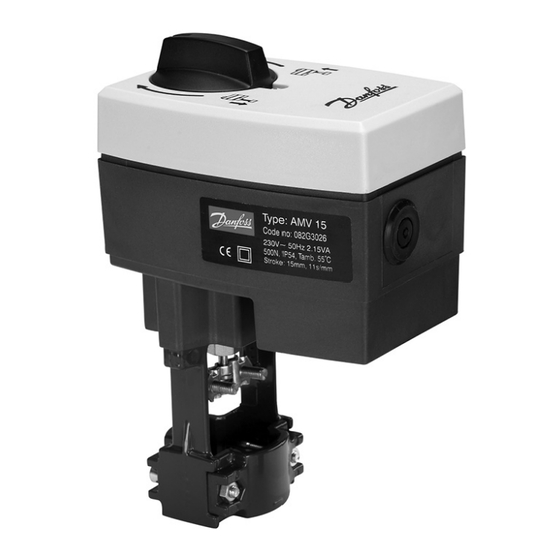
Fix the AME 15(ES), AME 16 actuator onto the valve.
External Switch Note
Information regarding the external ON/OFF switch for AME 15 ES.
Electrical Connections and Settings
Wiring Instructions
Details for connecting control signal, output signal, and supply voltage.
DIP Switch Configuration
Settings and factory defaults for DIP switches.
U/I Signal Control Selection
Configure actuator for voltage or current control signals.
Actuator Functional Modes
Spindle Direction Control
Set spindle travel direction based on control signal.
Sequential Operation Mode
Configure parallel or sequential control for multiple actuators.
Sequential Signal Range Configuration
Define specific signal ranges for sequential operation modes.
Proportional and 3-Point Operation
Configure proportional or simple 3-point control modes.
Flow Characteristics (LOG/LIN)
Select between logarithmic and linear flow characteristics.
Flow Rate Reduction (Kvs Adjustment)
Adjust maximum flow rate by reducing the Kvs value.
Operation and Testing Procedures
Reset Procedure
Steps to restart the self-adjustment procedure using the RESET switch.
Function Test Indicator
Interpreting the LED indicator for operational status and faults.
Need help?
Do you have a question about the VL 3 and is the answer not in the manual?
Questions and answers