Table of Contents
Advertisement
Quick Links
SPLIT-TYPE AIR CONDITIONERS
SERVICE MANUAL
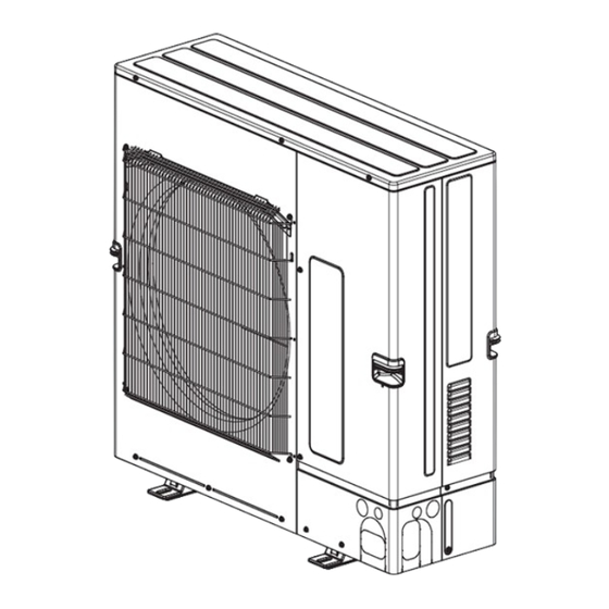
Outdoor unit
[Model Name]
PUZ-M100VKA2
PUZ-M100VKA2-ET
PUZ-M100VKA2-ER
PUZ-M125VKA2
PUZ-M125VKA2-ET
PUZ-M125VKA2-ER
PUZ-M140VKA2
PUZ-M140VKA2-ET
PUZ-M140VKA2-ER
PUZ-M100YKA2
PUZ-M100YKA2-ET
PUZ-M100YKA2-ER
PUZ-M125YKA2
PUZ-M125YKA2-ET
PUZ-M125YKA2-ER
PUZ-M140YKA2
PUZ-M140YKA2-ET
PUZ-M140YKA2-ER
[Service Ref.]
PUZ-M100VKA2.TH
PUZ-M100VKA2-ET.TH
PUZ-M100VKA2-ER.TH
PUZ-M125VKA2.TH
PUZ-M125VKA2-ET.TH
PUZ-M125VKA2-ER.TH
PUZ-M140VKA2.TH
PUZ-M140VKA2-ET.TH
PUZ-M140VKA2-ER.TH
PUZ-M100YKA2.TH
PUZ-M100YKA2-ET.TH
PUZ-M100YKA2-ER.TH
PUZ-M125YKA2.TH
PUZ-M125YKA2-ET.TH
PUZ-M125YKA2-ER.TH
PUZ-M140YKA2.TH
PUZ-M140YKA2-ET.TH
PUZ-M140YKA2-ER.TH
R32
PUZ-M100YKA2R1.TH
PUZ-M100YKA2-ETR1.TH
PUZ-M125YKA2R1.TH
PUZ-M125YKA2-ETR1.TH
PUZ-M140YKA2R1.TH
PUZ-M140YKA2-ETR1.TH
CONTENTS
1. REFERENCE MANUAL ······················· 2
2. SAFETY PRECAUTION ······················· 2
3. SPECIFICATIONS ···························· 13
4. DATA ·············································· 14
5. OUTLINES AND DIMENSIONS ··········· 17
6. WIRING DIAGRAM ··························· 18
7. WIRING SPECIFICATIONS ················ 22
9. TROUBLESHOOTING ······················· 29
10. FUNCTION SETTING ························ 77
BY THE REMOTE CONTROLLER ······· 78
12. EASY MAINTENANCE FUNCTION ······ 86
13. DISASSEMBLY PROCEDURE ············ 88
14. REMOTE CONTROLLER ··················· 95
PARTS CATALOG (OCB773)
January 2024
No.OCH773
REVISED EDITION-B
Revision:
• Connectable indoor units
have been added
in REVISED EDITION-B.
OCH773A is void.
Note:
• This service manual
describes technical data
of the outdoor units only.
Advertisement
Table of Contents

Related Manuals for Mitsubishi Electric Mr.Slim PUZ-M140YKA2


Summarization of Contents
REFERENCE MANUAL
INDOOR UNIT SERVICE MANUAL
Manual for indoor unit service operations.
SAFETY PRECAUTIONS AND REFRIGERANT HANDLING
SYMBOLS AND SAFETY OBSERVANCE
Meanings of unit symbols and general safety rules.
NEW REFRIGERANT CAUTIONS
Specific safety precautions for new refrigerants like R32.
SERVICE PROCEDURES AND WARNINGS
SERVICE WARNINGS AND CAUTIONS
General warnings and cautions for service operations and refrigerant handling.
SERVICE CAUTIONS AND REFRIGERANT CHARGING
Cautions for service and procedures for additional refrigerant charging.
R32 REFRIGERANT HANDLING CAUTIONS
Detailed cautions for units using R32 refrigerant during servicing.
R32 REFRIGERANT SERVICE AND RECOVERY
REPAIRS AND PROCEDURES FOR R32 UNITS
Cautions for repairs, detection methods, removal, evacuation, and charging.
REFRIGERANT RECOVERY AND DECOMMISSIONING
Procedures for refrigerant recovery, labeling, and decommissioning.
SERVICE TOOLS AND PIPE REUSE
EXCLUSIVE TOOLS FOR R32 REFRIGERANT
List of specialized tools required for R32 refrigerant.
REUSING EXISTING REFRIGERANT PIPES
Precautions and flowchart for reusing R22/R410A refrigerant pipes.
REFRIGERANT PIPING WORK CAUTIONS
REFRIGERANT PIPING WORK CAUTIONS
Cautions for refrigerant piping work including tool compatibility and dimensions.
INSTALLATION LOCATION GUIDELINES
OUTDOOR UNIT INSTALLATION LOCATION
Guidelines for choosing the correct installation location for outdoor units.
MINIMUM INSTALLATION AREA REQUIREMENTS
Requirements for minimum installation space to ensure safety.
MINIMUM INSTALLATION AREA FOR INDOOR UNITS
MINIMUM INSTALLATION AREA FOR INDOOR UNITS
Installation area requirements for various indoor unit types.
FLOOR STANDING UNIT INSTALLATION AREA
FLOOR STANDING UNIT INSTALLATION AREA
Specific installation area requirements for floor standing units.
SPECIFICATIONS
TECHNICAL SPECIFICATIONS OVERVIEW
General technical specifications for the outdoor units.
DATA
REFILLING REFRIGERANT CHARGE DATA
Data on refrigerant charge based on piping length.
COMPRESSOR TECHNICAL DATA
Technical data specific to the compressor unit.
NOISE CRITERION CURVES
NOISE CRITERION CURVES
Noise level data presented in criterion curves.
STANDARD OPERATION DATA
STANDARD OPERATION DATA
Standard operational data for various modes and conditions.
OUTLINES AND DIMENSIONS
UNIT DIMENSIONS AND PIPING/WIRING DETAILS
Physical dimensions and connection details for the unit.
WIRING DIAGRAM
WIRING DIAGRAM FOR PUZ-M100VKA2(-ET/-ER).TH
Electrical wiring diagram for a specific model.
WIRING DIAGRAMS FOR PUZ-M125/140VKA2 MODELS
Electrical wiring diagrams for PUZ-M125/140VKA2 models.
WIRING DIAGRAMS FOR PUZ-M100/125/140YKA2 MODELS
Electrical wiring diagrams for PUZ-M100/125/140YKA2 models.
WIRING DIAGRAMS FOR PUZ-M100/125/140YKA2R1 MODELS
Electrical wiring diagrams for PUZ-M100/125/140YKA2R1 models.
WIRING SPECIFICATIONS
FIELD ELECTRICAL WIRING SPECIFICATIONS
Power wiring specifications for different outdoor unit models.
SEPARATE INDOOR/OUTDOOR UNIT POWER SUPPLIES
Wiring patterns for separate indoor and outdoor unit power supplies.
INDOOR – OUTDOOR CONNECTING CABLE SPECIFICATIONS
Specifications for indoor and outdoor unit connecting cables.
M-NET WIRING METHOD AND EARTHING
Guidelines for M-NET wiring and proper earthing methods.
M-NET ADDRESS AND REFRIGERANT ADDRESS SETTINGS
Procedures for setting M-NET and refrigerant addresses.
REFRIGERANT SYSTEM DIAGRAM
REFRIGERANT FLOW AND COMPONENTS
Diagram illustrating the refrigerant system and its components.
REFRIGERANT COLLECTING (PUMP DOWN) PROCEDURE
Step-by-step procedure for collecting refrigerant (pump down).
TEST RUN START AND FINISH
Procedures for starting and finishing a test run operation.
TROUBLESHOOTING
SELF-DIAGNOSIS AND CHECK CODE SUMMARY
Overview of self-diagnosis codes and actions for troubleshooting.
TEST RUN CHECKPOINTS AND ERROR INFO
Checkpoints before test run and references for error information.
INDOOR UNIT ERROR CODES (OUTPUT PATTERN A)
List of error codes detected by indoor units with symptoms.
OUTDOOR UNIT ERROR CODES (OUTPUT PATTERN B)
List of error codes detected by outdoor units with symptoms.
SELF-DIAGNOSIS ACTION TABLE
ACTIONS FOR POWER ON ABNORMALITIES
Actions for abnormalities detected when the power is ON.
MISWIRING AND STARTUP TIME OVER ERRORS
Troubleshooting for miswiring and startup time over errors.
HIGH PRESSURE AND DISCHARGE TEMPERATURE ERRORS
Troubleshooting for high pressure and discharge temperature related errors.
THERMISTOR AND FAN MOTOR RELATED ERRORS
Troubleshooting for thermistor and fan motor errors.
POWER SUPPLY VOLTAGE AND CURRENT ERRORS
Troubleshooting for overvoltage, undervoltage, and current sensor errors.
REFRIGERANT AND PRESSURE RELATED ERRORS
Troubleshooting for low pressure and overheat protection errors.
COMPRESSOR AND REMOTE CONTROLLER ERRORS
Troubleshooting for compressor and remote controller communication errors.
COMMUNICATION ERRORS BETWEEN UNITS
Troubleshooting for indoor/outdoor unit communication errors.
REFRIGERANT AND PIPE TEMPERATURE ERRORS
Troubleshooting for refrigerant circuit and pipe temperature errors.
M-NET COMMUNICATION ERRORS
Troubleshooting for M-NET communication errors and address issues.
M-NET COMMUNICATION ERRORS (NO ACK SIGNAL)
Troubleshooting for M-NET "No ACK" signal errors.
TROUBLESHOOTING OF PROBLEMS
REMOTE CONTROLLER DISPLAY ISSUES
Troubleshooting for remote controller display problems.
M-NET COMMUNICATION RESPONSE ERRORS
Troubleshooting for M-NET response errors.
REMOTE CONTROLLER OPERATION ISSUES
Troubleshooting for remote controller operation and sound issues.
"PLEASE WAIT" DISPLAY TROUBLESHOOTING
Troubleshooting for the "Please Wait" display on the remote controller.
REMOTE CONTROLLER NO DISPLAY TROUBLESHOOTING
Troubleshooting for when the remote controller display shows no output.
REMOTE CONTROLLER NO DISPLAY TROUBLESHOOTING
Troubleshooting steps for a blank remote controller display.
REMOTE CONTROLLER NO DISPLAY TROUBLESHOOTING
Final troubleshooting steps for a blank remote controller display.
FREQUENT CUSTOMER CALLS AND RESPONSES
UNIT OPERATION AND REMOTE CONTROLLER ISSUES
Common customer issues regarding unit operation and remote controller.
COOLING PERFORMANCE AND SOUND ISSUES
Customer issues related to cooling performance and normal operational sounds.
SOUND AND AIRFLOW DIRECTION ISSUES
Troubleshooting for unusual sounds and airflow direction problems.
UNINTENDED OPERATION AND AIRFLOW ISSUES
Troubleshooting for unintended operation and fan speed mismatches.
MIST, WATER, AND REMOTE CONTROLLER DISPLAY ISSUES
Troubleshooting for mist, water expulsion, and dim/blank remote controller displays.
HOW TO CHECK THE PARTS
THERMISTOR RESISTANCE CHECK
Procedures for checking thermistor resistance values.
SOLENOID VALVE COIL AND MOTOR RESISTANCE
Checking resistance of solenoid valve coils and compressor motors.
DC FAN MOTOR AND CIRCUIT BOARD CHECK
Methods for checking DC fan motor and related circuit boards.
HOW TO CHECK THE COMPONENTS
THERMISTOR CHARACTERISTIC CHARTS
Charts showing thermistor resistance vs. temperature.
LINEAR EXPANSION VALVE OPERATION AND CHECK
Operation summary and connection details for the linear expansion valve.
LINEAR EXPANSION VALVE COIL ATTACHMENT/DETACHMENT
Procedures for attaching and detaching the linear expansion valve coil.
EMERGENCY OPERATION
CONDITIONS AND PROCEDURES FOR EMERGENCY OPERATION
When to use and how to perform emergency operation.
TEST POINT DIAGRAM
OUTDOOR CONTROLLER CIRCUIT BOARD DIAGRAM
Diagram showing test points on the outdoor controller circuit board.
OUTDOOR NOISE FILTER CIRCUIT BOARD LAYOUT
Layout of the outdoor noise filter circuit board.
OUTDOOR POWER CIRCUIT BOARD DIAGRAM
Diagram showing components on the outdoor power circuit board.
FUNCTION OF SWITCHES, CONNECTORS AND JUMPERS
DIP SWITCH FUNCTIONS AND OPERATION
Explanation of DIP switch functions and their actions.
CONNECTOR FUNCTIONS AND SPECIAL FEATURES
Explanation of connector functions and special features like low noise mode.
OUTDOOR UNIT INSPECTION INDICATORS
NORMAL AND ABNORMAL OPERATION INDICATIONS
Interpretation of LED indicators for normal and abnormal unit conditions.
DETAILED ERROR CODE INTERPRETATION
Detailed interpretation of error codes indicated by LED blinking patterns.
OUTDOOR UNIT OPERATION MONITOR FUNCTION
DIGITAL INDICATOR LED1 AND ERROR POSTPONEMENT
Explanation of LED1 indicators and error postponement displays.
BLINKING INDICATORS FOR INSPECTION CODES
Explanation of blinking indicators for various inspection codes.
MONITORING OPERATION DATA VIA REMOTE CONTROLLER
MONITORING TEMPERATURE AND CURRENT DATA
Display details for temperature, current, and history data.
MONITORING OPERATION AND POSTPONEMENT CODES
Display details for operation modes and postponement codes.
MONITORING ERROR HISTORY AND THERMISTOR DATA
Display details for error history and thermistor readings.
MONITORING THERMOSTAT TIME AND TEST RUN TIME
Display details for thermostat and test run times.
MONITORING INDOOR SETTING AND PIPE TEMPERATURES
Display details for indoor settings and pipe temperatures.
MONITORING CONNECTED UNITS AND CAPACITY SETTINGS
Display details for connected units and capacity settings.
MONITORING DEFROST CYCLES AND INPUT CURRENT
Display details for defrost cycles and input current.
MONITORING DISCHARGE SUPERHEAT AND OPENING PULSE
Display details for discharge superheat and LEV opening pulse.
MONITORING CAPACITY SAVE AND ERROR HISTORY
Display details for capacity save and error history.
MONITORING THERMISTOR AND OPERATION FREQUENCY ERRORS
Display details for thermistor and operation frequency errors.
MONITORING PIPE TEMPERATURE AND SUPERHEAT ERRORS
Display details for pipe temperature and discharge superheat errors.
MONITORING THERMOSTAT TIME UNTIL ERROR STOPS
Display details for thermostat time until error stops.
MONITORING INDOOR PIPE TEMPERATURES AND COMPRESSOR STATUS
Display details for indoor pipe temperatures and compressor status.
MONITORING COMPRESSOR SURFACE TEMPERATURE
Display details for compressor surface temperature.
FUNCTION SETTING
UNIT FUNCTION SETTING VIA REMOTE CONTROLLER
How to set unit functions using the remote controller.
SELECTING FUNCTIONS USING REMOTE CONTROLLER
How to select functions via the remote controller menus.
HOW TO MONITOR OPERATION DATA
HOW TO MONITOR OPERATION DATA USING REMOTE CONTROLLER
Guide on how to monitor operation data via the remote controller.
REQUEST CODE LIST FOR OPERATION DATA
REQUEST CODE LIST FOR OPERATION DATA
List of request codes to retrieve specific operation data.
REQUEST CODE LIST FOR OPERATION DATA
List of request codes to retrieve specific operation data.
REQUEST CODE LIST FOR OPERATION DATA
List of request codes to retrieve specific operation data.
OPERATION AND CONTROL STATE DETAILS
Detailed content for operation and control state request codes.
COMPRESSOR FREQUENCY CONTROL STATE DETAILS
Detailed content for compressor frequency control state request codes.
FAN CONTROL AND ACTUATOR OUTPUT STATE DETAILS
Detailed content for fan control and actuator output state request codes.
ERROR CONTENT (U9) DETAILS
Detailed content for error code U9 request codes.
DEMAND CAPACITY AND EXTERNAL INPUT STATE DETAILS
Detailed content for demand capacity and external input state request codes.
CAPACITY SETTING AND UNIT SETTING INFORMATION DETAILS
Detailed content for capacity setting and unit setting information request codes.
INDOOR UNIT CAPACITY SETTING INFORMATION DETAILS
Detailed content for indoor unit capacity setting information request codes.
WIRELESS PAIR NUMBER SETTING INFORMATION DETAILS
Detailed content for wireless pair number setting information request codes.
EASY MAINTENANCE FUNCTION
SMOOTH MAINTENANCE FUNCTION OVERVIEW
Overview of the Smooth Maintenance function for easier servicing.
OPERATION CONDITION GUIDE AND INSPECTION CRITERIA
OPERATION CONDITION GUIDE AND INSPECTION CRITERIA
Guide for operation conditions and criteria for inspection.
DISASSEMBLY PROCEDURE
REMOVING SERVICE PANEL AND TOP PANEL
Steps to remove the service and top panels of the unit.
REMOVING THE FAN MOTOR
Steps to remove the fan motor assembly.
REMOVING THE ELECTRICAL PARTS BOX
Steps to remove the electrical parts box.
DISASSEMBLING THE ELECTRICAL PARTS BOX (VKA2 TYPE)
Steps for disassembling the electrical parts box for VKA2 type units.
DISASSEMBLING THE ELECTRICAL PARTS BOX (YKA2 TYPE)
Steps for disassembling the electrical parts box for YKA2 type units.
DISASSEMBLING THE ELECTRICAL PARTS BOX (YKA2R1 MODEL)
Steps for disassembling the electrical parts box for YKA2R1 models.
REMOVING THE THERMISTOR <2-PHASE PIPE> (TH6)
Steps to remove the 2-phase pipe thermistor (TH6).
REMOVING THE THERMISTOR (TH7)
Steps to remove the ambient thermistor (TH7).
REMOVING THERMISTORS , ,
Steps to remove liquid, discharge, and comp. surface thermistors.
REMOVING THE LEV COIL
Steps to remove the LEV coil.
REMOVING THE LEV
Steps to remove the Linear Expansion Valve (LEV).
REMOVING THE HIGH PRESSURE SWITCH (63H)
Steps to remove the high pressure switch (63H).
REMOVING THE 4-WAY VALVE COIL (21S4)
Steps to remove the 4-way valve coil.
REMOVING THE 4-WAY VALVE
Steps to remove the 4-way valve.
REMOVING THE COMPRESSOR (MC)
Steps to remove the compressor unit.
REMOTE CONTROLLER
REMOTE CONTROLLER FUNCTIONS OVERVIEW
Explanation of the functions of the remote controller buttons.
REMOTE CONTROLLER DISPLAY MODES AND ICONS
Explanation of the remote controller's display modes and icons.
REMOTE CONTROLLER MENU STRUCTURE
MAIN MENU NAVIGATION AND SECTIONS
Overview of the remote controller's main menu structure and sections.
MAINTENANCE, SERVICE, SETTINGS, AND CHECK MENUS
Detailed breakdown of the maintenance, service, settings, and check menus.
REMOTE CONTROLLER MAIN MENU LIST
OPERATION AND TIMER FUNCTION SETTINGS
Details on setting operation modes and timer functions via remote.
ENERGY SAVING AND RESTRICTION SETTINGS
Details on setting energy saving, restriction, and silent modes.
INITIAL, DISPLAY, AND OPERATION SETTINGS
Details on initial, display, and operation settings via remote.
MAINTENANCE, SERVICE, SETTINGS, AND CHECK MENUS
Details on maintenance, service, settings, and check menu functions.
REMOTE CONTROLLER MODEL-SPECIFIC FUNCTIONS
PAR-SL97A-E CONTROLLER INTERFACE AND BUTTONS
Explanation of PAR-SL97A-E controller interface and button functions.
PAR-SL100A-E CONTROLLER INTERFACE AND BUTTONS
Explanation of PAR-SL100A-E controller interface and button functions.
ERROR INFORMATION
VIEWING AND RESETTING ERROR INFORMATION
How to check and reset error information on the remote controller.
CHECKING ERROR INFORMATION VIA MAINTENANCE MENU
How to view error information through the maintenance menu.
SERVICE MENU ACCESS AND NAVIGATION
ACCESSING THE SERVICE MENU AND PASSWORD ENTRY
Steps to access the service menu, including password entry.
SERVICE MENU CONTENT AND NAVIGATION
Explanation of the service menu content and screen navigation.
TEST RUN PROCEDURES
TEST RUN FOR PAR-41MAA AND OPERATION STEPS
Procedure for performing a test run on PAR-41MAA models.
TEST RUN FOR PAR-SL97A-E AND PAR-SL100A-E
Test run procedures for PAR-SL97A-E and PAR-SL100A-E models.
FUNCTION SETTING PROCEDURES
FUNCTION SETTING FOR PAR-41MAA MODEL
Steps for setting functions on PAR-41MAA models.
SETTING INDOOR UNIT ADDRESSES AND MODES
Setting indoor unit addresses, modes, and sending data.
REMOTE CONTROLLER FUNCTION SETTING METHODS
FUNCTION SELECTION PROCEDURE FOR PAR-SL97A-E
Procedure for selecting functions using the PAR-SL97A-E remote controller.
OPERATING INSTRUCTIONS FOR PAR-SL97A-E
Step-by-step operating instructions for the PAR-SL97A-E remote controller.
REMOTE CONTROLLER FUNCTION SETTING METHODS
FUNCTION SETTING PROCEDURE FOR PAR-SL100A-E
Procedure for setting functions using the PAR-SL100A-E remote controller.
ERROR HISTORY MANAGEMENT
ACCESSING AND VIEWING ERROR HISTORY
Steps to access and view the error history records.
DELETING THE ERROR HISTORY
Procedure for deleting error history records.
PRELIMINARY ERROR HISTORY AND DELETION
Managing preliminary error history records.
SELF-DIAGNOSIS
SELF-DIAGNOSIS FOR PAR-41MAA MODEL
Performing self-diagnosis on PAR-41MAA models.
INTERPRETING SELF-DIAGNOSIS RESULTS AND RESETTING ERRORS
Interpreting self-diagnosis results and resetting error history.
MALFUNCTION DIAGNOSIS METHODS
SELF-DIAGNOSIS FOR PAR-SL97A-E MODEL
Malfunction diagnosis method for PAR-SL97A-E models.
SELF-DIAGNOSIS FOR PAR-SL100A-E MODEL
Malfunction diagnosis method for PAR-SL100A-E models.
REMOTE CONTROLLER CHECK
ACCESSING AND PERFORMING REMOTE CONTROLLER CHECK
Steps to access and perform the remote controller check.
INTERPRETING REMOTE CONTROLLER CHECK RESULTS
Interpreting results of the remote controller check.
SMOOTH MAINTENANCE FUNCTION
ACCESSING AND SETTING SMOOTH MAINTENANCE
Steps to access and set the smooth maintenance function.
VIEWING OPERATION DATA FOR SMOOTH MAINTENANCE
Viewing operation data within the smooth maintenance function.
REQUEST CODE FOR OPERATION DATA
ACCESSING REQUEST CODES VIA SERVICE MENU
Steps to access request codes through the service menu.
SETTING REFRIGERANT ADDRESS AND REQUEST CODE
Setting refrigerant addresses and request codes for data retrieval.
Need help?
Do you have a question about the Mr.Slim PUZ-M140YKA2 and is the answer not in the manual?
Questions and answers